
Abstract
Purpose:
To evaluate the scattered and secondary radiation fields present in and around a passive proton treatment nozzle. In addition, based on these initial tests and system reliability analysis, to develop, install, and evaluate a radiation shielding structure to protect sensitive electronics against single-event effects (SEE) and improve system reliability.
Methods and Materials:
Landauer Luxel+ dosimeters were used to evaluate the radiation field around one of the gantry-mounted passive proton delivery nozzles at Loma Linda University Medical Center’s James M Slater, MD Proton Treatment and Research Center. These detectors use optically stimulated luminescence technology in conjunction with CR-39 to measure doses from X-ray, gamma, proton, beta, fast neutron, and thermal neutron radiation. The dosimeters were stationed at various positions around the gantry pit and attached to racks on the gantry itself to evaluate the dose to electronics. Wax shielding was also employed on some detectors to evaluate the usefulness of this material as a dose moderator. To create the scattered and secondary radiation field in the gantry enclosure, a polystyrene phantom was placed at isocenter and irradiated with 250 MeV protons to a dose of 1.3 kGy over 16 hours. Using the collected data as a baseline, a composite shielding structure was created and installed to shield electronics associated with the precision patient positioner. The effectiveness of this shielding structure was evaluated with Landauer Luxel+ dosimeters and the results correlated against system uptime.
Results:
The measured dose equivalent ranged from 1 to 60 mSv, with proton/photon, thermal neutron, fast neutron, and overall dose equivalent evaluated. The position of the detector/electronics relative to both isocenter and also neutron-producing devices, such as the collimators and first and second scatterers, definitely had a bearing on the dose received. The addition of 1-inch-thick wax shielding decreased the fast neutron component by almost 50%, yet this yielded a corresponding average increase in thermal neutron dose of 150% as there was no Boron-10 component to capture thermal neutrons. Using these data as a reference, a shielding structure was designed and installed to minimize radiation to electronics associated with the patient positioner. The installed shielding reduced the total dose experienced by these electronics by a factor of 5 while additionally reducing the fast and thermal neutron doses by a factor of 7 and 14, respectively. The reduction in radiation dose corresponded with a reduction of SEE-related downtime of this equipment from 16.5 hours to 2.5 hours over a 6-month reporting period.
Conclusions:
The data obtained in this study provided a baseline for radiation exposures experienced by gantry- and pit-mounted electronic systems. It also demonstrated and evaluated a shielding structure design that can be retrofitted to existing electronic system installations. It is expected that this study will benefit future upgrades and facility designs by identifying mechanisms that may minimize radiation dose to installed electronics, thus improving facility uptime.
Introduction
Clinical proton therapy systems in a hospital setting have been in use for nearly 25 years, 1 while protons and other ions have been used for patient treatment for 60 years since first being suggested by Robert Wilson. 2 These systems use high-energy protons to irradiate the target volume, 1,3,4 using the Bragg peak to minimize the number of treatment beams and hence the integral dose to the patient. Protons are delivered to the patient using 1 of 2 two modalities, passive or active. Passive techniques, which have been most commonly used in the clinical setting, spread the beam laterally using a combination of gold or lead and Lexan foils 5 and in depth using a rotating plastic wheel. 2 The beam is then collimated by brass or Cerrobend apertures and its penetration depth is varied by means of a wax/Lucite bolus or compensator. Active techniques 6 -9 employ a magnetically guided proton pencil beam in combination with dynamic changes in beam energy and beam intensity during treatment to conform dose to the target volume. Range shifters and apertures may also be employed with active delivery techniques to improve penumbra or depth of dose coverage.
Proton interactions with beam-modifying devices (such as scattering foils, modulator wheels, aperture, bolus/compensator, range shifter, etc) or within the patient can produce secondary particles, including photons, electrons, neutrons, and other ions. The impact of secondary particle dose to the patient has been studied extensively and reported by a number of groups 10 -16 ; values in the mSv/Gy to μSv/Gy range have been reported near the treatment field and within the patient. However, studies on the dose experienced by installed electronics within the treatment room itself have been limited. As treatment rooms become more sophisticated with onboard imaging, robotic patient positioners, and patient monitoring devices, the level of electronic systems and subsystems are increasing dramatically. Radiation interactions with microelectronic devices, such as microprocessors, semiconductor memory, or power transistors within these systems, can negatively impact operation and reliability; such interactions are known as single-event effects (SEE).
There are many types of SEEs, including single-event upset, single-event latchup, single-event gate rupture, and single-event transients; a good source for definitions of these effects can be found in Dodd and Massengill. 17 These effects have been studied over the decades 18 for space- and defense-based deployments of electronic systems. However, the rapid expansion of electronic systems into the area of radiation medicine means efforts in minimizing SEEs in the treatment room may need to be undertaken. The goal of this project was primarily to evaluate the scattered and secondary radiation fields present in and around a passive proton treatment nozzle in a clinical environment. Based on these initial tests and system reliability analysis, the project was expanded to include development, installation, and evaluation of a radiation shielding structure to protect sensitive electronics against SEE and hence improve system reliability. It is hoped that this study will serve as a benchmark and guide for upgrades and future installations in proton therapy, ensuring maximum facility uptime and reliability from radiation-induced SEE.
Methods and Materials
The first phase of this project was to evaluate the radiation environment present for electronics mounted on the proton gantry and around the gantry pit enclosure itself. The radiation fields present in these areas primarily comprise neutrons (fast, intermediate, and thermal) and gamma photons produced through proton interactions with the beam-modifying devices and patient. The detectors chosen for this study were the Luxel+ personnel-monitoring badges that are supplied by Landauer. 19 The Landauer Luxel+ dose-monitoring badges utilize 2 different detector systems, allowing for an accurate measurement of different radiation fields. Aluminum oxide (Al2O3) is used for the measurement of photons in an energy range of 5 to 40 MeV and is analyzed using optically stimulated luminescence. The Luxel+ detector system additionally utilizes CR-39 track detectors for the evaluation of both fast and thermal neutrons. These track detectors can measure fast neutrons in the energy range of 40 keV to 40 MeV and thermal and intermediate neutrons in an energy range of 0.25 eV to 40 keV. In addition to the wide range of particles and energies that can be detected, the Luxel+ system exhibits other advantages, including their small size, which allowed for a wide range of mounting options in this investigation.
Hypothesizing that secondary neutrons were the particle most impacting SEE and thus electronic device uptime, we also wanted to evaluate the ability of high-hydrogen-content material in potentially shielding electronic structures. To this end, we created custom-molded Luxel+ detector shields from machinable blue paraffin wax material provided by Freeman Manufacturing and Supply Company, Avon, Ohio (Figure 1). This material is used at our center for proton compensator manufacturer and can be melted and recast a number of times. The detector shields were constructed to have a wall thickness of 1 inch all around the detector with a machined cap and step fit to reduce leakage through the cap–body interface. Detectors with and without paraffin wax shields were placed around the proton gantry enclosure on cabinets housing electronic systems (Figure 2). It should be noted that these systems are located in the gantry enclosure, which is the floor below the treatment room and hence approximately 18 feet below isocenter with an interspaced concrete floor and robotic patient positioner turntable. Detectors were also attached to gantry-mounted electronic systems (Figure 3) that had been identified by system engineers to house processor-based systems that may be impacted by SEE.

Landauer Luxel+ detector (left) and paraffin wax shield (right). Note the step in the shield–cap interface to limit leakage through this interface.
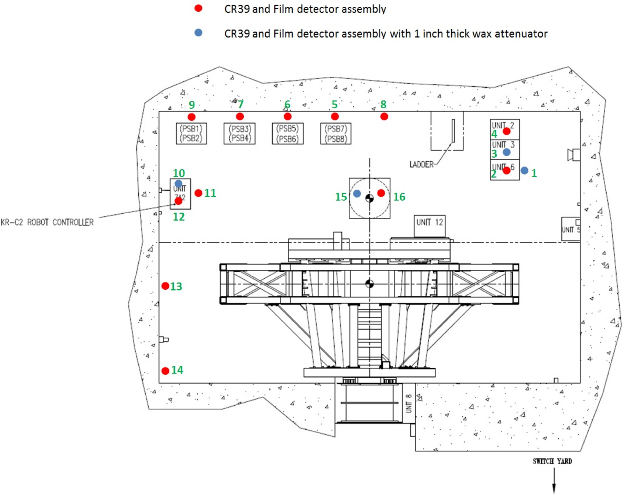
Schematic of detector positions around the gantry pit enclosure. Kuka robot controller cabinet is labeled as the KR-C2 robot controller.

Schematic of detector positions on the Loma Linda University Medical Center’s proton gantry.
One disadvantage of passive detector systems like the Luxel+ is that they do not provide immediate feedback of dose at a given experimental condition. As such, consideration had to be given to construct an experiment that reflected a “worst-case scenario” under which the electronics would be operated. To this end, 250 MeV protons were chosen as they would have the highest cross section for the production of nuclear secondaries from the clinically employed proton energies at Loma Linda University Medical Center (LLUMC). All clinical scattering foil settings were employed; an 8 cm diameter aperture and a 6 cm modulator wheel were used to shape the beam, as these represent average values of what is available in this treatment room (aperture size from 0 to 13 cm diameter and beam modulations from 1.5 to 14 cm). A 40 × 40 × 40 cm 3 polystyrene phantom was used to represent the patient in this test. A total dose of 1286 Gy delivered over 16 hours, with dose divided equally (±10%) between gantry angles of 0°, 90°, 180°, and 270°, was employed to reflect clinical reality.
At the completion of this initial study, the measured radiation field experienced by electronic systems was correlated against this “unknown” but possibly radiation-induced downtime experienced by these systems. The Gantry 1 treatment room utilizes a Kuka 6 degree-of-freedom robotic patient positioner (KUKA Robotics Corporation, Shelby Township, MI, USA) for the treatment of patients. Its controller cabinet, located in the gantry pit enclosure (identified in Figure 2), was identified as an electronic system that may benefit from radiation mitigation efforts. In a 12-month period preceding this study, this system experienced 36 hours of downtime that was possibly attributed to SEE, as no other cause was identified. It should be noted that while this represents a downtime of only 0.41% in this treatment room (there are 4 in the facility), at all times we endeavor to minimize downtime because the facility operates 24/7 with patient treatment, calibration, research, and maintenance operations (a facility uptime goal is better than 98% 20 ). Relocating this system to another part of the facility, not impacted by radiation, was an option for minimizing radiation downtime; however, this option was disregarded due to the cost and further impact on clinical operations as the cabinet was being relocated. Accordingly, radiation shielding efforts were undertaken and evaluated, as presented subsequently.
Results and Discussion
Data for all measurement locations are tabulated in Table 1, which can be correlated with measurement locations outlined in Figures 2 and 3. Fast neutrons deliver the majority of dose to electronics within the gantry enclosure and mounted to the gantry itself; values are, on average, 5 and 8 times higher than photon and thermal neutron doses. As such, we determined that future radiation mitigation and shielding efforts needed to focus on minimizing dose from this component of the secondary radiation spectra to have greatest impact on system uptime.
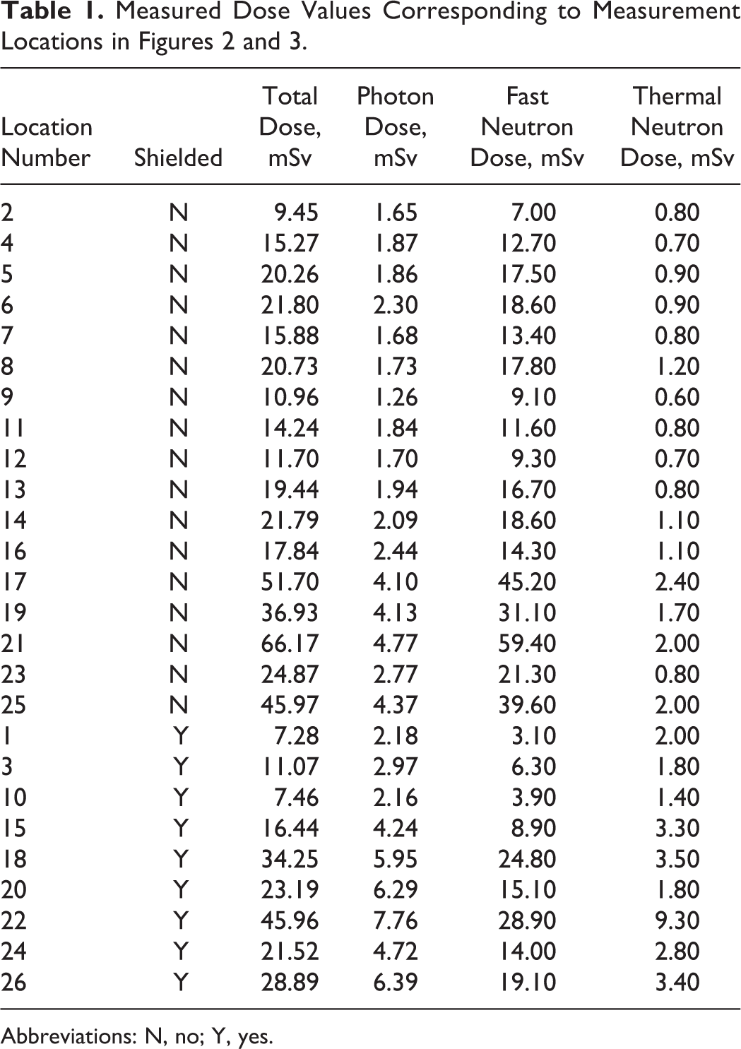
Abbreviations: N, no; Y, yes.
Dosimetric results for positions around the pit enclosure are displayed in Figure 4. They indicate that the dose received at a given point is highly dependent on the position relative to isocenter. Positions 9 and 11 demonstrate the lowest dose equivalent readings and these are correspondingly the farthest from isocenter. Fast neutrons are certainly the most predominant radiation in this region, with dose values approximately 10 and 20 times higher than photon or thermal neutron doses, respectively. The fast neutron dose measured in these locations corresponded to a dose of 7.1-14.5 μSv/Gy delivered at isocenter, which, while relatively low, provides us a means for estimating the total dose experienced by these electronic systems over a period of time, given the workload of the room.
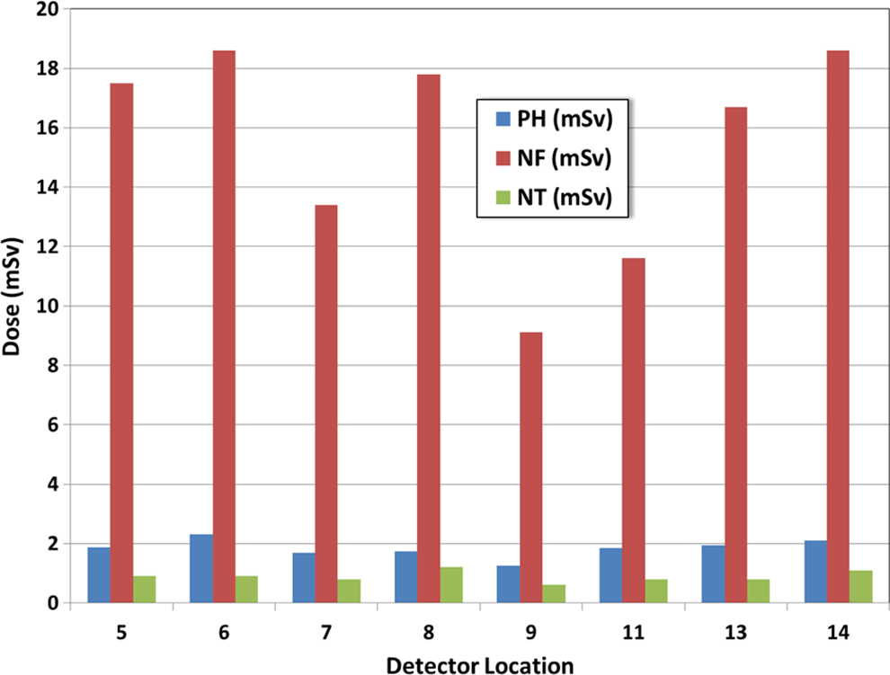
Dose breakdown for locations around the pit enclosure (see Figure 2 for corresponding locations). Dose data are provided for photons, fast neutrons, and thermal neutrons.
Locations on the gantry received approximately 3 to 6 times higher doses than locations on the gantry pit floor (Figure 5), which is attributed to their closer proximity to structures producing secondary particles, such as the scattering foils and precollimators. The location on the gantry itself, relative to isocenter, also has a bearing on the dose delivered. This is clearly seen in the comparison of points 21 and 23 (refer to Figure 3) when location of the device farther from isocenter, while remaining on the gantry, results in an almost 3-fold decrease in fast neutron dose. This would support ensuring that more sensitive electronics be placed lower down in the racks on future installations and hence farther from the scattering foils and collimators.

Part of this study was also to investigate the possibility of shielding these structures with materials either commonly found in a radiotherapy department (blue paraffin wax) or with commercially available materials (such as borated plastic). Luxel+ detectors were placed in 1-inch-thick enclosures made out of blue paraffin wax and placed in the same locations as the unshielded detectors. The results (Figure 5) indicate that the presence of a hydrogen-rich material such as wax did reduce fast neutron dose by a factor of 50% on average. Likewise the total dose delivered was lowered by 27%, on average, when a high hydrogen content material was used in a shielding application. However, with these dose reductions came a significant increase in thermal neutron dose (average increase of 150% and a maximum increase of 365%) and also a lesser increase in photon dose of 27% to 74%. These increases can be attributed to the lack of an agent such as Boron-10 to capture thermal neutrons and also a lack of a higher Z layer to attenuate photons. The results emphasized to us that care must be taken in choosing the correct shielding material for the application and that a layered structure may be required to help attenuate the mixed secondary radiation field produced by a proton therapy nozzle.
In reviewing the above-mentioned results, it was clear that a layered borated plastic structure would be significantly more effective at shielding electronics from the secondary particle spectra produced through normal clinical operations. When comparing the radiation analysis to suspected radiation-induced downtime, the Kuka control cabinet was identified as a piece of equipment that could benefit from radiation mitigation efforts. To achieve this aim, a shielding structure was constructed from King Plasti-Shield (King Plastic Corporation, North Port, Florida), which is a Boron-enhanced polyethylene product used for neutron shielding applications. The 5% Boron by weight (purple) Plasti-Shield was employed for this work; the material has a weight density of 0.035 pounds per cubic inch. A four-sided shielding structure was produced, as displayed in Figure 6, with the other 2 sides shielded by the concrete wall and floor of the gantry enclosure. The sides of the shielding structure were composed of three inches of 5% King Plasti-Shield, with an inner layer of 0.125-in thick aluminum to assist in attenuation of any photons released during the neutron capture process and also to provide a level of structural rigidity to the shield. Lead and even steel were more favorable options here but were ruled out due to difficulty in manufacturing and impact to the structure’s weight.

The shielding structure constructed and installed to shield patient positioner electronics within the gantry pit enclosure.
The structure was assembled off-site and then brought into the proton treatment area in pieces, moved into position using a crane, and then assembled. All joints of the shielding structure were constructed with an overlapping design to minimize leakage while also bolstering the structural integrity of the overall design. The front of the shielding structure employed an external hinge to minimize door gaps and leakage into the shielded enclosure, while retaining the ability to access the space for servicing needs. As in the initial study, Landauer Luxel+ dose monitoring badges were adhered to the outside and inside of the shielding structure to evaluate its effectiveness at shielding electronics from secondary radiation. Data were collected over a 6-month period of normal patient operations and compared to downtime that is attributed to this system.
The results of the radiation analysis (Table 2) indicated that the installed shielding structure reduced the total dose experienced by these electronics by a factor of 5, while additionally reducing the fast and thermal neutron doses by a factor of 7 and 14, respectively. The reduction in radiation doses corresponded with a reduction in SEE-related downtime of this equipment, from 16.5 hours to 2.5 hours (a 6.6-fold decrease) over a 6-month reporting period. This demonstrates how the fast neutron dose and downtime of electronic systems can be linked and that radiation mitigation efforts can impact facility uptime. In this case, the benefits were minimal, decreasing the downtime by 14 hours over a 6-month period; however, in a facility where such a high demand is placed on it for clinical and research operations, any benefit to uptime should be considered.
Radiation Measurement Results Both Inside and Outside the Installed Radiation Shield Over a 6-Month Period.a

a Multiple detectors were placed inside and outside the shield for accuracy and redundancy.
b Difference, % calculated as (External Average - Internal Average) / Internal Average * 100.
This article provides an overall estimate of the dose delivered to electronics mounted on a gantry and within the gantry pit enclosure of a clinical passive proton therapy system. The results indicate that the secondary radiation environment can impact the uptime of the facility and that radiation mitigation efforts, such as locating away from the source of radiation and employing shielding, can be used to decrease radiation-induced damage and improve equipment reliability. However, shielding electronic components can be a relatively costly option and requires consideration of factors such as serviceability, adequate venting for computer systems, structural integrity, and so on. These factors make shielding of multiple structures within this environment potentially a nonviable solution for many centers. Certainly, placing electronics in locations outside the radiation environment seems an ideal solution; however, on existing installations such an upgrade would result in considerable facility downtime while the upgrade is completed. Even in new installations, the relocation of electronic systems to a satellite location can introduce other complicating issues such as electronic noise and increased capacitance from longer cable runs as well as difficulty in servicing and troubleshooting equipment errors. Another option to improve facility uptime is to replace standard electronic components with radiation-resistant alternatives that are used in the space and defense industries, but these also have their own complicating factors including cost, compatibility, and availability.
From a radiation shielding aspect, another option to consider is to shield the source of the secondary particles, particularly the fast neutrons. The components in a passive proton nozzle producing these particles are well known 15 and include the first and second scattering foils, precollimators, and aperture. These high-Z materials have a high cross section for neutron production and, in the case of the scattering foils and precollimators, are fixed within the proton beam line. In the above-mentioned results, this is clearly demonstrated with position 21 (closest proximity to the scattering system) receiving a dose approximately 5 times higher than locations around the gantry pit enclosure. Encasing the first and second scatterer housing and precollimators in 1 to 4 in of borated polyethylene may prove to be a cost-effective solution to the issue of radiation mitigation to electronics within the treatment room. Shielding these neutron-producing structures would benefit all electronics in the room without the cost and complications (e.g. venting) associated with shielding individual electronic components. The shielding of such structures may further reduce out-of-field doses experienced by the patient. 13,14,16 Such doses, although low, should be minimized where possible, especially for pediatric patients. Further work to demonstrate this hypothesis is planned and will include measured dose equivalent as well as simulated neutron fluence analysis and evaluation of the silicon microdosimetry spectra. This will help in the optimization of the nozzle shielding concept and provide a more complete evaluation of the secondary particle spectra.
As proton therapy continues to develop and expand, two different types of facility are being produced. The original design is the large facility with a central accelerator and multiple treatment rooms. 1,20 Facilities with this design have been in clinical operation for almost 25 years and were the subject of study in this research. More recently, single-room systems are being developed; in these, the accelerator, beam-modifying devices, and electronics are generally mounted on a single gantry located in a single treatment vault. These self-contained systems have a much smaller physical footprint, but the above-mentioned results suggest that the compact design may increase the secondary radiation exposure of associated electronic systems, potentially impacting uptime. Similar studies of such systems would be a worthwhile direction of future work as the industry moves forward.
Conclusion
The measured data obtained in this study provide a baseline for radiation exposures experienced by gantry- and pit-mounted electronic systems. The position of the detector/electronics relative to both isocenter and also neutron-producing devices, such as the collimators and first and second scatterers, definitely had a bearing on the measured dose. This work also demonstrated and evaluated a shielding structure design that can be retrofitted to existing electronic system installations. This shielding structure reduced secondary radiation doses and associated electronic downtime and highlighted the effectiveness of shielding; however, it was hypothesized that such shielding may be better applied to the sources of secondary particles (scattering foils and precollimators) in future radiation mitigation efforts. It is expected that this study will benefit future upgrades and facility designs by identifying mechanisms that may minimize radiation dose to installed electronics, thus improving facility uptime.
Footnotes
Abbreviation
Acknowledgments
The authors would like to acknowledge the support of the Engineering and Field Service teams at Optivus Proton Therapy, including Tim King, Ed Lee, David Lesyna, Mark Porter, Erick Cortes, and Nick Rigney for their support of this project. Also the support of the Accelerator Operations Group at Loma Linda University Medical Center was instrumental in assisting with experiments presented in this manuscript.
Declaration of Conflicting Interests
The author(s) declared no potential conflicts of interest with respect to the research, authorship, and/or publication of this article.
Funding
The author(s) received no financial support for the research, authorship, and/or publication of this article.