
Abstract
Image registration techniques based on anatomical features can serve to automate patient alignment for intracranial radiosurgery procedures in an effort to improve the accuracy and efficiency of the alignment process as well as potentially eliminate the need for implanted fiducial markers. To explore this option, four two-dimensional (2D) image registration algorithms were analyzed: the phase correlation technique, mutual information (MI) maximization, enhanced correlation coefficient (ECC) maximization, and the iterative closest point (ICP) algorithm. Digitally reconstructed radiographs from the treatment planning computed tomography scan of a human skull were used as the reference images, while orthogonal digital x-ray images taken in the treatment room were used as the captured images to be aligned. The accuracy of aligning the skull with each algorithm was compared to the alignment of the currently practiced procedure, which is based on a manual process of selecting common landmarks, including implanted fiducials and anatomical skull features. Of the four algorithms, three (phase correlation, MI maximization, and ECC maximization) demonstrated clinically adequate (ie, comparable to the standard alignment technique) translational accuracy and improvements in speed compared to the interactive, user-guided technique; however, the ICP algorithm failed to give clinically acceptable results. The results of this work suggest that a combination of different algorithms may provide the best registration results. This research serves as the initial groundwork for the translation of automated, anatomy-based 2D algorithms into a real-world system for 2D-to-2D image registration and alignment for intracranial radiosurgery. This may obviate the need for invasive implantation of fiducial markers into the skull and may improve treatment room efficiency and accuracy.
Keywords
Introduction
Two-dimensional (2D) and volumetric (three-dimensional [3D]) image registration techniques are widely used to map 2D and 3D image sets, respectively, with each set consisting of a fixed reference image and a captured image in order to estimate the optimal transformation between the objects represented by them. These techniques are used in medical applications, including image-based patient registration for image-guided radiation procedures, 1 and have shown to provide benefits over interactive alignment procedures. 2 In the cases of patient alignment using 2D-to-2D techniques, two orthogonal digitally reconstructed radiographs (DRRs) of a computed tomography (CT) scan conducted during the treatment planning phase act as the reference images, while digital x-ray images captured in the treatment room act as the images to be registered. If automated, this scenario can present significant time and potentially accuracy gains over user-dependent methods.
At Loma Linda University Medical Center (LLUMC), fiducial markers and internal bony anatomy are used in combination with a 2D-to-2D image registration technique based on orthogonal x-rays to DRR reference images for patient alignment during intracranial radiosurgery treatments. Four titanium fiducial screws are implanted into the cranium of the patient up to 1 week prior to immobilization and imaging studies. The implanted fiducials add to the accuracy of the manual alignment process but may delay patients starting treatment while also adding an element of pain and stress to the patient as they must undergo an additional surgical procedure prior to radiation treatment. It is hypothesized that an automated 2D image registration technique would render the implanted fiducials unnecessary for intracranial radiosurgery while maintaining or improving alignment accuracy compared to current manual alignment techniques.
We investigated the suitability of entirely anatomy-based, automated 2D-to-2D image registration algorithms for intracranial radiosurgery by comparing four image registration algorithms to alignment results obtained with the currently established user-dependent registration method. The particular algorithms chosen for this research were tested using a rigidly immobilized and indexed human skull (Figure 1). This research was designed to provide a fundamental comparison between image registration techniques that will be carried into the next phase of research before implementation. Orthogonal DRRs and in-room 2D x-ray images of a human skull were used to evaluate the different registration methods for accuracy, robustness, and performance. The results of this study indicate that an automated patient alignment system using 2D image registration can provide significant improvements to all forms of external beam radiation therapy. Beyond gains in accuracy and efficiency, it will remove the human element that can cause variation from training/experience to impact the quality of patient alignment. As automated alignment techniques utilize the bony anatomy of the patient, implanted fiducials may no longer be required thus removing the need for additional surgery or delay prior to treatment.

Photograph of the rigidly immobilized human skull positioned in the treatment room used for testing.
Materials and Methods
Alignment Images
Orthogonal DRRs and corresponding in-room 2D x-ray images of a human skull (Figure 1), which was rigidly and reproducibly positioned on the treatment table, were used to evaluate the different image registration algorithms. The human skull was chosen as it provided a clinically realistic case for alignment testing, while the rigid immobilization and indexing to the patient support system provided a level playing field for all algorithms. The alignment tests were completed in the Gantry 1 treatment room, which comprises of a robotic patient positioner that is linked to a 2D orthogonal x-ray imaging system. The 2D imaging system consists of two retractable imaging panels arranged at 90° to one another, the readout of which is linked to the digital image alignment software (Figure 2). The technique used for capturing the 2D x-ray images of the human skull used in this study was 70 kVp and 10 mAs. 3
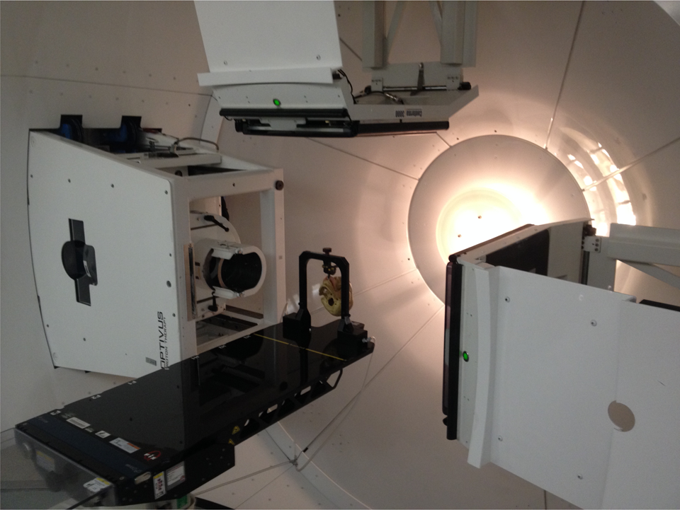
Photograph of the Gantry 1 treatment room where the human skull was positioned for testing. Note the extended digital imaging panels for imaging and alignment.
The orthogonal DRRs (Figures 3A and 4A), obtained from a high-resolution scan using a treatment planning CT scanner and converted to Digital Imaging and COmmunications in Medicine (DICOM) format (to allow for use with MATLAB), served as the reference images, while the in-room 2D x-ray images (Figures 3B and 4B), initially saved in a proprietary digital image format and later converted to DICOM, served as the captured images to be registered. The orthogonal DRR images had a reconstructed field of view size of 409.59 mm, a matrix size of 512 × 512 px2, and a corresponding pixel size of 0.8 mm per px, while the 2D x-ray images had a field of view of 274.53 mm, a matrix size of 1024 × 1024 px2, and a corresponding pixel size of 0.27 mm per px. Due to the difference in pixel size, the captured images were rescaled to fit the matrix size of the reference images.

Reference (A) and captured (B) two-dimensional (2D) anterior image set of the human skull used for registration.
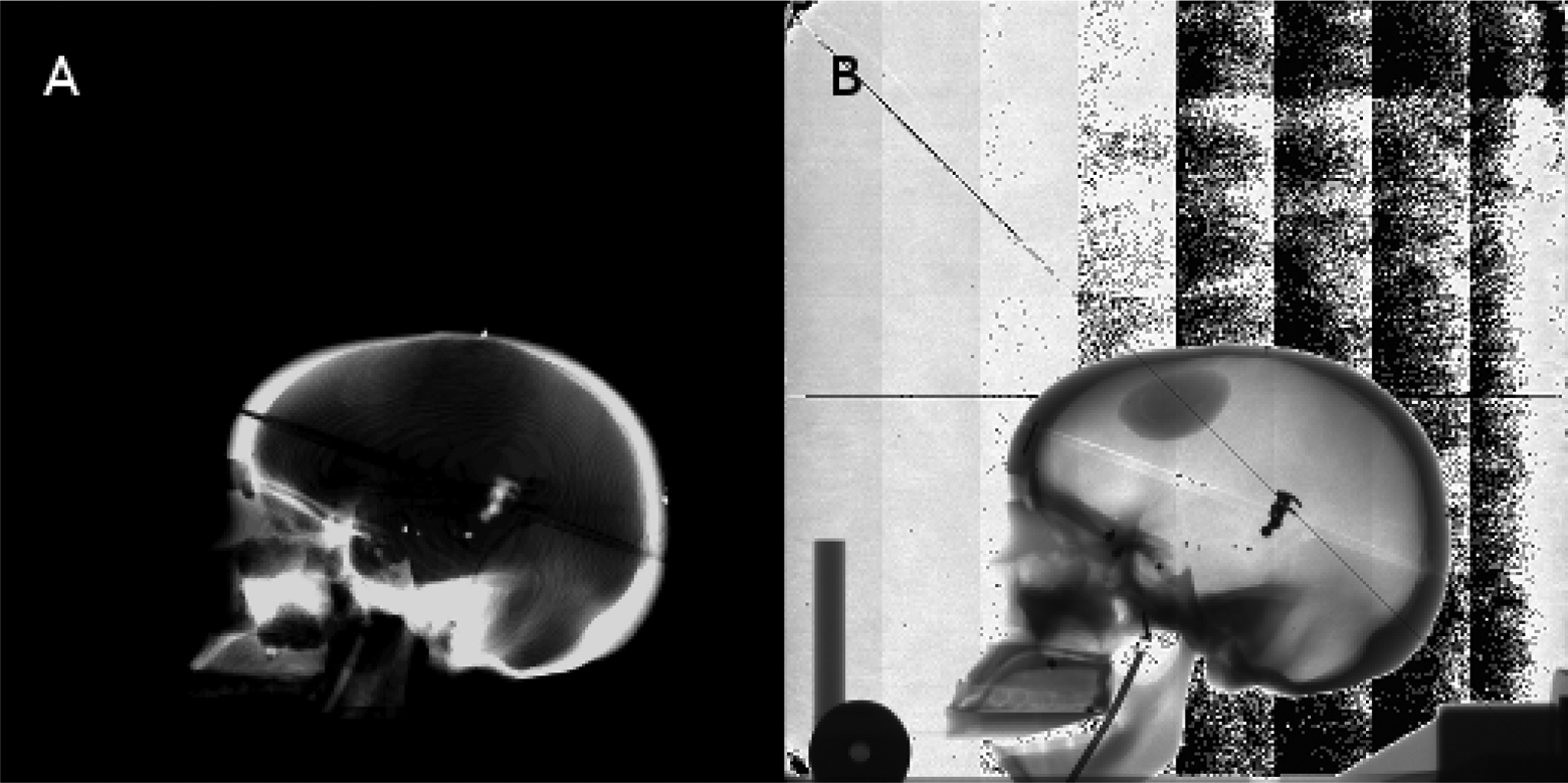
Reference (A) and captured (B) two-dimensional (2D) lateral image set of the human skull used for registration.
Automated and User-Dependent, Interactive Alignment
All DICOM images were loaded into MATLAB as image matrices and separately as information objects for each image in order to use the image properties for determining scale adjustments between the images and converting from millimeter measurements to a pixel-based coordinate system. The reference and captured images were processed using the different algorithms tested in this work, as shown subsequently. The resultant three translations (lateral, longitudinal, and vertical) and two rotations (pitch and yaw) were compared for accuracy with those determined by the currently practiced interactive alignment technique performed by a trained treatment technician.
The standard alignment technique is based on the interactive comparison of anterior and lateral captured image sets with corresponding DRR reference images. The user selects discrete anatomical and implanted fiducial screw landmarks in the captured and reference images, respectively. Typically four screws and six to eight anatomical landmarks are chosen. The internal (proprietary) alignment algorithm performs a least-square minimization procedure based on the landmarks to determine a rigid 2D transformation (two translations and pitch or yaw rotation). From phantom testing (not presented here), this method is accurate to within ±0.5 mm and ±0.5°, respectively. The typical (or expected) execution time for the user-dependent, interactive alignment procedure is 3 to 5 minutes per image.
Image Registration Algorithms
Four different image registration algorithms were assessed for accuracy, robustness, and performance. These algorithms included the fast Fourier transform (FFT)-based phase correlation technique using log-polar coordinates, 4 the mutual information (MI) maximization method, 5 the enhanced correlation coefficient (ECC) maximization method, 6 and the iterative closest point (ICP) method. 7
The phase correlation (FFT) technique is an image registration algorithm performed in the frequency domain to take advantage of several properties of the Fourier transform for simple transformations. The peak of the phase correlation between the reference and captured images is the translational difference between the two images. Extending this technique by converting the images from the Cartesian coordinate system to a log-polar coordinate system, 4 the rotational difference can be obtained using the same method. For this algorithm, bilinear interpolation was used to convert between the coordinate systems.
Mutual information is a metric derived from probabilistic measures of image intensity values.
5
This algorithm uses the joint probability distribution of the reference and captured images to iteratively measure the certainty that the captured image maps to the reference image. Mutual information is defined as:

where p(x, y) is the joint probability distribution function and p(x) and p(y) are the marginal probability distribution functions, and x and y are the intensities of pixels for the images X and Y, respectively. The sums extend over all pixels in each image.
The ECC method 6 maximizes the linear dependence between the reference and captured images in order to achieve the optimal alignment. This algorithm uses an iterative forward additive approach, sacrificing computational efficiency for better accuracy. The difference from other ECC metrics, such as an inverse compositional approach, is that the forward additive approach uses an approximated parameter vector that is optimized during each iteration until its norm becomes smaller than a predefined threshold set by the user.
The ICP method 7 is an iterative, feature-based algorithm that essentially works in two steps. Each iteration first matches points based on the latest transformation estimate then refines the estimate based on the matches. This algorithm is simple to implement and allows the user to choose optimal subroutines for feature detection and closest point calculation. Several corner detection algorithms were implemented as subroutines for testing, including the Harris corner detector, 8 the Shi and Tomasi minimum eigenvalue method, 9 and the FAST corner detector. 10,11 In addition, multiple nearest neighbor search algorithms for finding the closest points between the images were also tested, but only the results for the K-D tree nearest neighbor search are presented in this article, inasmuch as it was the fastest of the three methods.
Each algorithm was programmed for execution in the MATLAB environment using the image processing toolbox. The hardware used was a laptop with an AMD Turion X2 Dual-Core Mobile RM-75 processor and 4 GB of RAM. This is significant because implementing these algorithms on a dedicated system using a more efficient environment will provide further benefits in terms of speed.
Results
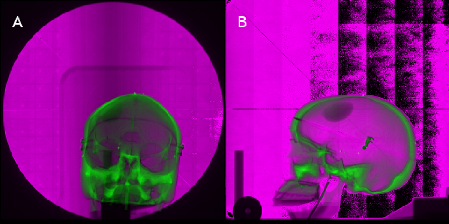
Both the numerical transformation results and the visual representation of the alignments for each algorithm are presented in this section. For visual comparison, each image set consists of the captured image overlaid atop the reference image. The reference and captured images are shown in an overlay fashion to visually demonstrate the accuracy of each algorithm. The green and magenta coloring scheme shows the difference in the intensity values of the images, that is, the green coloration denotes a higher intensity value for a given pixel location for the reference image, while the magenta coloration denotes a higher intensity value for a given pixel location for the captured image. Figure 5 shows the overlaid unregistered anterior (Figure 5A) and lateral (Figure 5B) image sets to demonstrate the degree of alignment obtained by each of the automated registration methods.

Two-dimensional (2D) anterior (A) and lateral (B) image sets of the human skull registered using the fast Fourier transform (FFT)-based phase correlation technique.

Two-dimensional (2D) anterior (A) and lateral (B) image sets of the human skull registered using mutual information maximization.
Figures 6 and 7 show the comparisons of the overlaid registered images using the phase correlation algorithm and MI algorithm, respectively. For both algorithms, these results show that the displacement after alignment between the registered images is very small (<0.75 mm), meaning that these algorithms appear to be highly accurate. The visual results of these algorithms are nearly identical, and the reader is referred to the numerical results for these registrations shown in Tables 1 and 2. As the FFT algorithm failed to provide a value for rotation for either anterior or lateral image sets, the value in the tables has been marked as not applicable (N/A). Note that this algorithm still attempted a registration for rotation, which could impact the time for alignment. If this rotational alignment was ignored and translations considered only, there could be a possible time improvement in the alignment process for the FFT algorithm.
Registration Results for the 2D Anterior Image Set.a
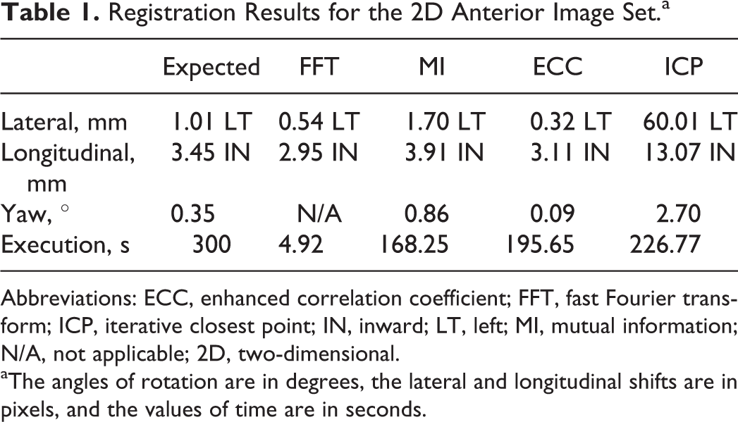
Abbreviations: ECC, enhanced correlation coefficient; FFT, fast Fourier transform; ICP, iterative closest point; IN, inward; LT, left; MI, mutual information; N/A, not applicable; 2D, two-dimensional.
aThe angles of rotation are in degrees, the lateral and longitudinal shifts are in pixels, and the values of time are in seconds.
Registration Results for the Lateral Image Set.a

Abbreviations: DN, down; ECC, enhanced correlation coefficient; FFT, fast Fourier transform; IN, inward; ICP, iterative closest point; MI, mutual information; N/A, not applicable.
aThe angles of rotation are in degrees, the lateral and longitudinal shifts are in pixels, and the values of time are in seconds.
Figures 8 and 9 display the unregistered images with the registered images obtained from the ECC maximization method and the ICP algorithm, respectively. Like the results for the previous algorithms, the results for the ECC maximization algorithm show that it is a potential candidate for implementation for patient alignment. Complications arose with the ICP algorithm due to the noise present in these images causing erroneous feature detection. Because the point clouds for the reference and captured images were unmappable to each other, this algorithm provided clinically unacceptable registration results. The most likely reason was its sensitivity to image noise, which was present in the captured images (see Discussion).

Two-dimensional (2D) anterior (A) and lateral (B) image sets of the human skull registered using enhanced correlation coefficient (ECC) maximization.

Two-dimensional (2D) anterior (A) and lateral (B) image sets of the human skull registered using an iterative closest point (ICP) algorithm.
Tables 1 and 2 show the registration results (coordinate transformations and rotations required for registration) for the 2D anterior and lateral image sets, respectively. The expected values in the left-most columns are the result of the user-dependent, interactive alignment process and are given for comparison. The run time for each algorithm was calculated using MATLAB's built-in stopwatch timer. Even with the hardware limitations for this study, the time until final registration for each algorithm surpassed the expected execution time.
Discussion
We have compared the registration results of four automated 2D alignment methods to that of the current clinically practiced user-dependent alignment method. The results show that three of these methods—log-polar phase correlation, MI maximization, and ECC maximization—were within ±1 mm with respect to translation and ±1° with respect to rotation as returned by the manual alignment process, which is the current clinical standard at our institution. The ICP algorithm, however, failed on all accounts of alignment due to poor point cloud generation. Due to the nature of the captured images, noise was incorrectly identified as point-like features in the image, which caused the generation of random points that did not map between the reference and captured images. Also of note is the fact that all algorithms outperformed interactive alignment in terms of completion time, and the fastest of the algorithms (FFT-based phase correlation) provided a substantial speed-up of the alignment process (seconds vs minutes).
The three suitable algorithms demonstrate sufficient accuracy and performance to carry into further optimization and testing. Since the manual method in combination with suitable immobilization techniques 12 is itself accurate to within ±0.5 mm, 13 one can conclude that these three algorithms are plausible candidates for future testing of clinical data sets or against other techniques. The phase correlation algorithm produced no value for rotation; however, this algorithm is attractive for its accuracy in translation and, in particular, speed in comparison with the other algorithms. The ICP algorithm gave clinically unsuitable alignment results. The most likely reason was its sensitivity to image noise, which was present in the captured images. Investigation into noise filtering or region of interest (ROI) registration techniques for future work may allow for improving the overall registration accuracy of these algorithms. It should be noted, however, that increased user involvement (ie, ROI selection, etc) could impact the time for alignment of the algorithm.
In the present study, we compared several automated registration techniques against each other. However, a successful implementation may not be limited to a single method. Instead, a number of potential options are available for effectively combining the top performing algorithms. A simple system with multiple processors, each processor simultaneously running a separate algorithm, will allow for a more optimal alignment as different orientations of the patient may have different computation requirements. For example, in the case studied, the 2D anterior image generally contains less noise and thus does not require as robust of an algorithm with respect to this type of artifact, while the 2D lateral image contains a larger amount of noise and will require an algorithm that is robust in the presence of image noise. The performance of each algorithm could be compared using a phantom in the treatment room, and the most optimal of these for each of the two imaging lines would be selected for clinical use. A potential drawback to this method, however, is that not all results would be available until all algorithms have completed execution, resulting in the overall process only being as fast as the slowest algorithm. On the other hand, with modern computing technology, the execution time would likely be clinically acceptable.
Although commercial systems such as the BrainLAB ExacTrac X-Ray 6D system 14 are available for clinical deployment, the goal of this study was to investigate, at a fundamental level, algorithms that could be employed for patient alignment. The results of this study serve as the basis for future work toward the development and clinical implementation of an automated patient alignment system at LLUMC and may also assist other investigators in this mission where commercial systems are not easily integrated. More robust testing on multiple clinical data sets and different anatomical sites is planned as the next milestone toward this goal. The work presented here has identified algorithms for further testing and also identified other techniques, including those employed in ROI registration algorithms, which may also be considered for future research.
Conclusion
This work has shown that anatomy-based, automated, and 2D image registration is a viable technique to accelerate the process of patient alignment over the standard interactive, point-based method. While no single tested algorithm provided optimal registration on all accounts, each algorithm provided an increase in speed that could be further enhanced with appropriate computer hardware acceleration. The FFT-based phase correlation, ECC maximization, and MI maximization algorithms demonstrated sufficient translational accuracy and performance benefits to warrant further optimization, clinical testing, and potential clinical implementation. Applying an imaging-line-specific algorithm based on performance is another direction for application as it will allow the ability to select the algorithm that provides the best results for a given imaging line.
Footnotes
Abbreviations
Acknowledgments
The authors would like to acknowledge the support of Tom S. Lee from Optivus Proton Therapy for sharing his expertise of the Digital Imaging and Communications in Medicine (DICOM) medical imaging file format. The authors would also like to acknowledge Grant McAuley from Loma Linda University for assisting in the peer review process for this article.
Declaration of Conflicting Interests
The author(s) declared no potential conflicts of interest with respect to the research, authorship, and/or publication of this article.
Funding
The author(s) received no financial support for the research, authorship, and/or publication of this article.