
Abstract
Introduction
A bolus is a material that is placed on the surface of a patient's skin during radiation therapy to help ensure that the correct dose of radiation is delivered to the targeted volume.1-–3 Conventional techniques of bolus fabrication involve creating a custom mold of the patient's body and then casting the bolus material in the mold. This procedure can be time-consuming and may not be suitable for patients with complex shapes or irregular surfaces. With 3D printing, boluses can be quickly and easily customized to fit the exact shape of a patient's body. A 3D scanner can be used to create a digital model of the patient's body, which can then be used to create a 3D model of the bolus. The bolus can be printed using a range of materials, including thermoplastic materials that can be heated and molded to the patient's skin. 3D printed boluses have been shown to be effective in ensuring accurate radiation dose delivery in patients.4–10 They can also reduce the time and cost associated with traditional bolus fabrication methods. However, it's important to note that 3D printed boluses may require additional testing and validation to ensure their safety and effectiveness. In the fight against cancer center of Setif (CLCC-Setif), Algeria, a national project is being conducted aiming at the implementation of such 3D printing and modeling technologies for bolus fabrication.
When selecting a material for 3D printing radiotherapy boluses, several important criteria must be considered, including the following:
Radiological properties: The material used for the bolus should have radiological properties similar to those of human tissue. This means that the radiation beam should be attenuated in a manner similar to that of human tissue to ensure accurate dose delivery. Tissue-equivalence: The material should be tissue-equivalent, which means that it should have a density and atomic number similar to those of human tissue. This helps ensure that the radiation dose is delivered accurately to the target area. Biocompatibility: The material should be biocompatible and nontoxic to ensure patient safety. Moldability: The material should be easily moldable to the patient's skin to ensure that it conforms to the patient's body shape. Stability: The material should be stable over time and not degrade or change shape or size, which could affect the accuracy of the radiation dose.
Some common materials used for 3D printing radiotherapy boluses include thermoplastic materials such as polystyrene and polyethylene, and materials such as liquid silicone rubber and hydrogels. Each material has its own advantages and disadvantages, and the choice of the material will depend on the specific requirements of the patient and the treatment plan. In terms of performance criteria, the 3D printed bolus should be evaluated for its accuracy in dose delivery, conformity to the patient's body, and stability over time. This can be achieved using techniques such as dosimetry measurements and quality assurance testing. The performance of the bolus should be validated before its use in a clinical setting to ensure patient safety and treatment efficacy.
As a first phase in the implementation of 3D printing and modeling technologies at the CLCC-Setif, the 3D printing materials of interest were studied for patient's bolus printing purpose. Two commercially available 3D printing materials were initially selected: polylactic acid (PLA) and thermoplastic polyurethane (TPU). These materials were thoroughly characterized and qualified. On the studied 3D printing material and fabricated boluses, necessary tests and analyses were conducted: Fourier-transform infrared (FTIR) spectroscopy, thermogravimetric analysis (TGA), differential scanning calorimetry (DSC), dynamic mechanical analysis (DMA), metrology and wearing compatibility tests, bolus positioning and Hounsfield unit (HU) verification by x-ray CT scan, and dosimetric response verification by thermoluminescence (TL) dosimetry. The results of the tests and analysis allowed the selection of more suitable 3D printing materials and the evaluation of the fabricated bolus quality.
Materials and Methods
3D Printing Technology for Radiation Therapy
3D printing technology, also known as additive manufacturing, is the process of creating 3D objects by layering materials on top of each other.11–13 The process involves taking a digital 3D model and slicing it into layers, which are then printed layer by layer using a 3D printer. There are several different 3D printing technologies, including fused deposition modeling (FDM), stereolithography (SLA), digital light processing (DLP), and selective laser sintering (SLS), among others. Each technology uses different methods and materials to create the final object.
3D printing technology, including FDM, has various applications, including manufacturing, healthcare, architecture, and fashion. It allows the creation of complex geometries that are difficult or impossible to fabricate using traditional manufacturing methods. In healthcare, 3D printing technology is being used to create patient-specific medical devices, implants, prostheses, and organs. It can also be used to create anatomical models for surgical planning and education, and to create customized tools and devices for medical procedures.
3D printing technology has a range of applications in radiation therapy, including the following:
Bolus fabrication: As we discussed earlier, 3D printing can be used to create customized boluses that conform to the patient's body shape and ensure accurate dose delivery. Patient-specific immobilization devices: 3D printing can be used to create patient-specific immobilization devices that hold the patient in place during radiation therapy. These devices can be designed to fit the patient's body shape precisely, which can help reduce the risk of patient movement and ensure accurate dose delivery. Phantom fabrication: 3D printing can be used to create phantoms, which are objects that simulate human tissue and are used for testing and calibration purposes in radiation therapy. 3D printing allows for the creation of highly precise and customized phantoms that can be used to test treatment plans and equipment. Treatment planning: 3D printing can be used to create models of the patient's anatomy that can be used for treatment planning. These models can help identify the precise location of the target area and surrounding tissues, which can help optimize treatment plans and reduce the risk of adverse events. Shielding: 3D printing can be used to create customized shielding devices that protect sensitive tissues and organs during treatment.
Overall, 3D printing technology can improve the accuracy and precision of radiation therapy by allowing highly customized and patient-specific treatment solutions. However, it is important to ensure that any 3D-printed devices or materials used in radiation therapy respond optimally to all functionality and safety criteria. 3D printing technology use is growing rapidly in radiation therapy and is expected to become even more important in the future.
In this work, bolus fabrication using FDM technology is considered.14–16 The main criteria and technical procedure aiming to select the 3D printing material are discussed on the basis of the characterization and testing results obtained on the considered materials.
Preliminary Selection of 3D Printing Materials
When selecting a material for FDM 3D printing of a radiation therapy bolus, it is important to consider several factors, including the material's chemical and physical properties, biocompatibility, and ability to attenuate radiation conformably in treatment planning. The first class of materials we select for radiation therapy bolus fabrication is thermoplastic elastomers (TPE), such as TPU. TPEs have a rubber-like texture, making them comfortable to wear and mold to the body. TPEs also have good biocompatibility, meaning they are unlikely to cause any adverse reactions in the patient.17–19 In terms of radiation attenuation, PLA is a suitable material due to its high atomic number and density, which makes it an effective radiation dose modulator.20–22 However, it is important to note that PLA is not as flexible as TPU, so it may not be suitable for all applications. Another material option is acrylonitrile-butadiene-styrene (ABS), which has a density similar to that of PLA but is more flexible, making it suitable for certain applications. However, ABS can release toxic fumes during printing, so it is important to use appropriate ventilation.
Ultimately, the material choice will depend on the specific requirements of the radiation therapy bolus, including the location of the treatment area, the required bolus thickness, and the patient's individual needs and preferences. It is always best to consult with a radiation oncologist or medical physicist to determine the most appropriate material for a particular application.
In this work, 2 candidate materials are studied and compared, namely: ANYCUBIC compatible TPU (1.75 mm) and PLA (1.75 mm), owing to their advantages and characteristics. Boluses and testing samples were printed under the conditions and parameters listed in Table 1. These conditions were fixed according to the recommendations of the 3D printing materials’ manufacturer and of the exigence of the targeted application in terms of the filling rate (dose-response) and surface roughness (adequacy to receiving surface). The FDM 3D printing machine is “Raise3D Pro2 Plus.” This machine refines 3D printing for production-grade environments by upgrading and evolving traditional manufacturing. It is equipped with a dual extrusion system with retracting hot ends and 4× increased torque performance. The massive build volume is 305 × 305 × 605 mm3 with a layer height of 0.01 mm. For printing security and environmental protection, the printer is equipped with a camera and HEPA air filter. The machine is compatible with diverse filaments (up to 300 °C).
3D Printing Conditions and Parameters.

Bolus Design and 3D Printing Model Generation
The radiotherapy bolus fabrication procedure of this work involved the following steps:
Shape definition and sizing of the bolus: The radiation therapy bolus is a device used to increase the radiation dose delivered to the target zone of the patient's body during a radiation therapy session. It can be used to compensate for dose loss due to radiation beam divergence away from the skin or to increase the dose at more superficial depths. Designing a radiation therapy bolus is an important step in the treatment planning process performed by clinicians in the treatment planning system (TPS). To design the bolus, the clinician must consider several factors, such as the location of the tumor, depth of the target zone, radiation dose to be delivered, maximum tolerable dose to surrounding healthy tissues, and properties of the patient's tissue. The TPS provides tools that allow clinicians to determine bolus shape and thickness based on these factors. nce the bolus is designed, the TPS calculates the radiation dose delivered to the patient by including the bolus. The clinician can then adjust the treatment parameters to ensure that the delivered radiation dose meets the treatment goals defined for each patient. Data extraction from the TPS and 3D model creation: For the 3D printing of the bolus virtually created by the clinician on the TPS, the data referring to it (axial, coronal, and sagittal slices) are extracted and processed, if necessary, by a computer-aided design (CAD) program. The CAD program is only required for the bolus created by the medical physicist to be processed. Extracting data from the TPS and creating a 3D model of the bolus to be printed are important steps in the process of designing and printing a 3D model of the radiation therapy bolus. To extract data from the TPS, all data were first exported into DICOM (Digital Imaging and Communications in Medicine) format. The extracted data include CT slices and all treatment-planning details, namely: target and surrounding tissue contours, treatment plans, planned radiation doses, and bolus parameter shape as defined by the clinician. The data is then imported into our 3D modeling software. Using these data, the 3D modeling software creates a 3D model of the bolus. The 3D model can be customized for each patient and adjusted to fit the treatment machine used to deliver the radiation dose. Generally, when work is well done by an experienced medical physicist, the created bolus with the TPS does not present any artifacts. If necessary, the 3D model created can be processed in the next step by adequate smoothing and elimination of certain artifacts to make it more precise and comfortable for the patient. In addition to commercial CAD software, many open-access tools and software can be used for the last task such as ‘MeshLab (v.2021.05)’. The 3D model created and processed is stored in the “STL” format that can be 3D-sliced for final 3D printing.
In this study, boluses to be received by the nose and cheek were 3D printed by considering real radiotherapy treatment cases in a virtual patient (physical phantom) by introducing Rando phantom CT scan data into the TPS.
3D Printing Material Analysis, Characterization, and Testing
Fourier-Transform Infrared Spectroscopy
FTIR spectroscopy was used to analyze the chemical composition of TPU and PLA in 3D printing. The objectives of the FTIR analysis of TPU and PLA are the following23,24:
Identification of TPU and PLA based on their characteristic absorption bands. Characterization of the chemical compositions of the functional groups in TPU and PLA and their relative concentrations. Detection of contaminants and the presence of impurities and contaminants in the TPU and PLA samples.
The TPU and PLA samples were prepared by cutting a small piece from a 3D-printed filament into pellets. A calibrated IRAffinity-1s SHIMADZU instrument was used. The spectral resolution of the instrument was set to 4 cm−1 to analyze the complex mixture of TPU and PLA. The instrument was baseline-corrected to eliminate any interference from background absorption. FTIR spectra were acquired in the attenuated total reflectance mode in the spectral range of 4000 to 450 cm−1. The signal-to-noise ratio was also optimized to ensure that the sample signal was distinguishable from the instrument noise. A diamond standard optical material is used. The absorbance mode should be selected with a suitable number of scans.
10
TPU and PLA exhibit distinct absorption bands that can be used to characterize their chemical composition. TPU exhibited characteristic absorption bands at 1700 and 1530 cm−1 that correspond to the carbonyl group and aromatic ring, respectively. PLA exhibited characteristic absorption bands at 1750 and 1180 cm−1 that correspond to the carbonyl group and the C-O stretching, respectively. By analyzing the relative intensities of these absorption bands, the concentrations of TPU and PLA in the samples could be determined. Any impurities or contaminants in the sample can also be identified based on their characteristic absorption bands.
Thermogravimetric Analysis
TGA is a thermal analysis technique used to investigate the thermal stability and decomposition behavior of materials as a function of temperature. TGA can be used to analyze the thermal behavior of TPU and PLA, the 2 tested 3D printing materials. The main objectives of the TGA analysis of TPU and PLA are namely: the determination of thermal stability by measuring the temperature at which studied material begin to decompose, identifying decomposition products during the thermal degradation of TPU and PLA, and comparing the thermal behaviors of TPU and PLA under different conditions. 25
In the TGA analysis carried out, TPU and PLA samples were prepared by cutting small pieces from 3D-printing filaments and grinding them into fine powder. The samples were then weighed and placed in a TGA pan. The used TGA instrument (SETARAM Labsys™TG-DTA12) was calibrated using a standard reference material to ensure accurate and reproducible measurements. The heating was set to a constant value of 10 °C/min until 500 °C was reached to ensure reproducible measurements. The TGA experiment was performed in an argon atmosphere. The sample weight was optimized, as mentioned in the results section, to ensure that it was sufficient to produce a measurable signal but not so large that it would mask the decomposition signal. The TGA instrument was baseline-corrected to eliminate any drift or background signals.
Differential Scanning Calorimetry
DSC was used to study the behavior of materials when heated or cooled. The method is based on measuring the heat flux entering or leaving the sample. The sensor output is in watts (W). It allows us to determine the following phase transitions
26
:
The glass transition temperature (Tg) of the studied material Melting (Tm) and crystallization (Tc) temperatures Reaction enthalpies to determine the crosslinking rates of certain polymers. Hold at 1.0 min at 30.00 °C Heat from 30.00 °C to 180.00 °C at 10.00 °C/min Hold for 1.0 min at 180.00 °C. Cool from 180.00 °C to 30.00 °C at 10.00 °C/min. Hold for 1.0 min at 30.00 °C. Heat from 30.00 °C to 180.00 °C at 10.00 °C/min Hold for 1.0 min at 180.00 °C. Cool from 180.00 °C to 30.00 °C at 10.00 °C/min. Hold for 1.0 min at 30.00 °C.
In this study, a PerkinElmer DSC instrument was used by considering the IndCal method. Measurements were performed with indium as a reference, a measured enthalpy of 38.413 J/g, and nitrogen at 20.0 mL/min using a Kalman filter. The sample weights were 6.860 mg (PLA) and 5.540 mg (TPU). The following protocol was used:
Dynamic Mechanical Analysis
DMA measures the storage and loss modules of a material (in Pascal (Pa)) as a function of time, temperature, or frequency. An additional output also shows the calculated without the unit Tangent Delta (δ) damping factor. 27 The storage modulus of a material represents the elastic energy stored during deformation and provides information about polymer stiffness. It measures the material's elastic behavior. Similarly, the loss modulus is the ratio of the viscous (out-of-phase) component to the stress. 27 It is related to the material's ability to dissipate stress through heat. The tangent delta (Tan (Delta)) is a measure of the dissipation of energy in a material. In this study, the 9.53 IUT VITRY Discovery HR-2 DMA instrument was used. Measurements were performed under the experimental conditions presented in Table 2.
Experimental Conditions of the DMA.

Roughness and Surface Finish
In additive manufacturing (3D printing) and bolus design for targeted applications, analysis of the surface roughness and surface finish of selected 3D printing materials (TPU and PLA) is crucial. The achievable surface finish tolerance largely depends on the 3D printing technology and the parameters used. Different 3D printing processes (eg, FDM, SLA, and SLS) have different inherent capabilities for achieving surface finish. In this study, the roughness and surface finish were experimentally evaluated. The evaluation of surface roughness (Ra) involves several steps and typically follows standardized procedures. Ra is a parameter commonly used to quantify the average surface roughness.
In this study, optical profilometry was used for the indirect measurement of Ra and for qualitative and quantitative characterization of the surface finish. The 3D manufactured parallelepiped samples (10
Functionality and Printing Performance Testing
Metrological Accuracy Checking of the Printed Bolus
Metrology is the scientific study of measurement. It is an essential part of the quality control process in manufacturing and ensures that products meet the required specifications. In the case of a 3D-printed radiotherapy bolus, metrology is used to verify that the dimensions of the bolus are accurate and meet the required tolerances. The metrology and wearing compatibility test of a 3D-printed radiotherapy bolus involves measuring the dimensions of the bolus and comparing them to the required specifications. This test can be performed using various measurement tools, such as calipers, micrometers, and light and laser scanners. Metrology and wearing compatibility testing are crucial steps in the quality control of 3D-printed radiotherapy boluses. To ensure accurate measurements, appropriate measurement techniques and well-established protocols must be used. This includes ensuring that the measurement tools are calibrated and that measurements are taken at appropriate points on the bolus. Once the measurements were taken, the data were analyzed to determine whether the dimensions of the bolus were within the required tolerances. By ensuring that the dimensions of the bolus are accurate and within the required tolerance ranges, we can be confident that the bolus will be easily worn, will perform its function as expected, and will provide the necessary dose-response during treatment. In this work, a metrology test was performed by measuring the thicknesses and densities of the final fabricated boluses using an accurate caliper (AGL 0-150 mm, accuracy 0.005 mm) and digital analytical balance (120 g/0.1 mg, 5134 INT).
Dosimetric Response Test
Dosimetric response verification of the 3D printing material plays a crucial role in ensuring accurate and safe delivery of radiation treatment to patients. The measurement of Percentage Depth Dose (PDD) in a water phantom is a common procedure for measuring the beam quantity and dose delivery in radiation therapy. At the CLCC-Setif, the PDD was measured using a PTW Semiflex 0.125 cm3 (PTW 31010) ionization chamber and automatic 3D PTW water phantom MP3 under reference exposure conditions (the source-to-surface distance (SSD) was set to 100 cm) according to a standard protocol. In this work, point doses were measured at different depths of the studied 3D printing materials (PLA and TPU) and compared to doses measured at the same depths in water by the ionization chamber. Point dose verification was performed by thermoluminescence dosimetry (TLD-100 (photon) and TLD-200 (electron)).28,29 Thus, 14- and 28-mm-thick plates were manufactured using the 3D printing materials to be tested in order to vary the depth and measure point doses. After exposure, the dose was measured using a Riso DA-20 TL/OSL reader. The measured dose values were compared to the water-PDD values to evaluate whether the dose-response of the studied materials was conformed or not.
Hounsfield Unit Verification
The HU of a printed radiotherapy bolus should be checked for several reasons:
Treatment Planning Accuracy: The HU of a material indicate its radiodensity, which is crucial for treatment planning. If the HU of the printed bolus material is inaccurate, incorrect calculations of the radiation dose can be made and potentially compromise the effectiveness of the treatment. Tissue Equivalency: The bolus material should have HU values that are similar to those of the surrounding tissue it is attempting to replicate. Significantly different HU values can result in under- or over-dosing of the target area. Dose Calculation Accuracy: TPSs use HU values to calculate the radiation dose distribution within the patient. Accurate HU values ensure that the dose calculations are reliable. Quality Assurance: Quality assurance ensures that the treatment plan and dose delivery are as accurate as possible, reducing the risk of errors that could harm the patient.
In this work, the variation in HU as a function of the 3D printing material infill was studied by varying it from 5% to 100%. Several 3D printed testing samples (3
Bolus Positioning Verification
In the radiotherapy bolus fabrication process, it is essential to ensure that the bolus meets exactly the surface on which it will be placed without any gaps or air cavities. This type of verification can be performed using a CT scanner after placing the bolus on the received surface.
In this work, to check the wearing conditions and suitability of the fabricated boluses, they were placed on a Rando phantom and CT-scanned. If the bolus does not meet the required specifications, it may need to be reprinted after model re-adjustment to ensure that it is suitable for use in radiotherapy treatment and comfortable for the patient.
Biocompatibility and Safety
Biocompatibility, safety, and cytotoxicity are crucial considerations when using materials like TPU and PLA in the fabrication of radiotherapy boluses, as these devices come into direct contact with the patient's skin for extended periods. In vitro assays for skin irritation and skin sensitization assessment of medical devices are now included in ISO 10993-23 and ISO 10993-10, respectively. Together with the in vitro methods for cytotoxicity assessment included in ISO 10993-5, these methods offer an ethical alternative to animal testing with human relevance and high accuracy. In this work, a literature review of the biocompatibility, safety, and cytotoxicity issues of the studied 3D materials for targeted applications is presented.
Results
Preselection of the 3D Printing Material
TPU and PLA are materials that can be used in 3D printing for radiation therapy bolus fabrication. However, TPU has several advantages over PLA for this application, including:
Flexibility: TPU is more flexible than PLA, allowing it to conform to the shape of the patient's body more easily. This is particularly important for irregular surfaces, such as the face and neck, where rigid boluses may not conform well. Durability: TPU is more durable than PLA, which is important for boluses that may be used repeatedly or for extended periods. TPU is less likely to crack or break, which helps ensure consistent dose delivery. Density: TPU has a higher density than PLA, which is important for achieving the desired dose distribution. A denser material can provide a more uniform dose distribution and reduce the risk of hot spots. Water resistance: TPU is more water-resistant than PLA, which is important for boluses that may come into contact with water or sweat. This can help ensure consistent dose delivery and reduce the risk of hot spots.
Overall, TPU's flexibility, durability, density, and water resistance make it a better choice than PLA for radiation therapy bolus fabrication. However, the material choice ultimately depends on the specific application and desired properties of the bolus.
Characterization of Selected 3D Printing Materials, Analysis, and Testing
Results of FTIR Characterization
The FTIR characterization results of PLA and TPU are shown in Figures 1 and 2. The PLA FTIR spectrum (Figure 1) clearly shows C=O and O–H stretch regions within the intervals of 1800 °C to 1680 °C and of 4000 to 3200 cm−1 respectively. The peaks at approximately 1750 and 1180 cm−1 refer to C=O stretching and the C–O–C stretching of PLA. Other identified bands were indexed on the PLA FTIR spectrum presented in Figure 1. The FTIR results demonstrate that TPU is an ester-polyurethane (Figure 2). Moreover, the studied TPU did not contain any mineral addition. The obtained FTIR spectrum shows a signal related to NH stretching in the range of 3300 to 3000 cm−1. Symmetric and asymmetric methylene bands were observed at 3000 to 2800 cm−1. The band at around 2340 cm−1 indicates the isocyanate region in the TPU. The FTIR spectrum also shows CN stretches, C-O-C stretches, CO stretching at 1733 to 1700 cm−1, C=C skeletal stretch of the benzene ring at 1590 cm−1, and CN stretches at 1527 cm−1. Our results can be compared to already published results by taking into consideration that 3D printing materials manufactured from similar basic polymers are subjected to slightly different FTIR properties due to specific additives that can be used.30,31
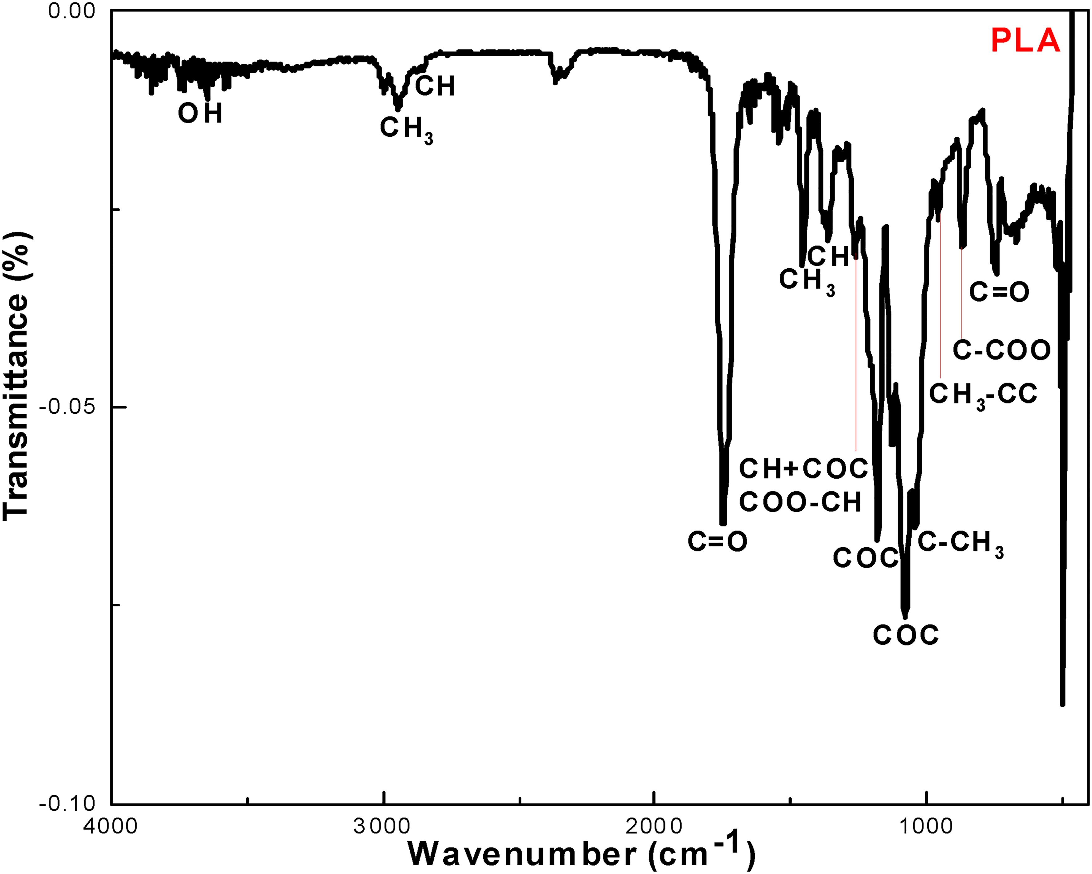
Fourier-transform infrared (FTIR) spectrum of polylactic acid (PLA).

Fourier transform infrared (FTIR) spectrum of thermoplastic polyurethane (TPU).
Results of TGA Analysis
The TGA results for TPU and PLA are presented in Figures 3 and 4. TPU typically shows a 2-stage decomposition pattern, with the first stage occurring at around 330 °C and the second stage occurring at around 400 °C, whereas PLA typically shows a single-stage decomposition pattern, with the decomposition starting at around 320 °C. 32 The TGA spectrum of TPU shows 2 shoulders within the temperature interval of 280 °C to 450 °C. The reason for this 2-stage degradation is the different decomposition behaviors of the urethane and polyester bonds. 33 The degradation temperatures of both 3D printing materials were significantly higher than the printing temperatures of both materials (180°C-230 °C).

Thermogravimetric (TGA) spectrum of thermoplastic polyurethane (TPU).
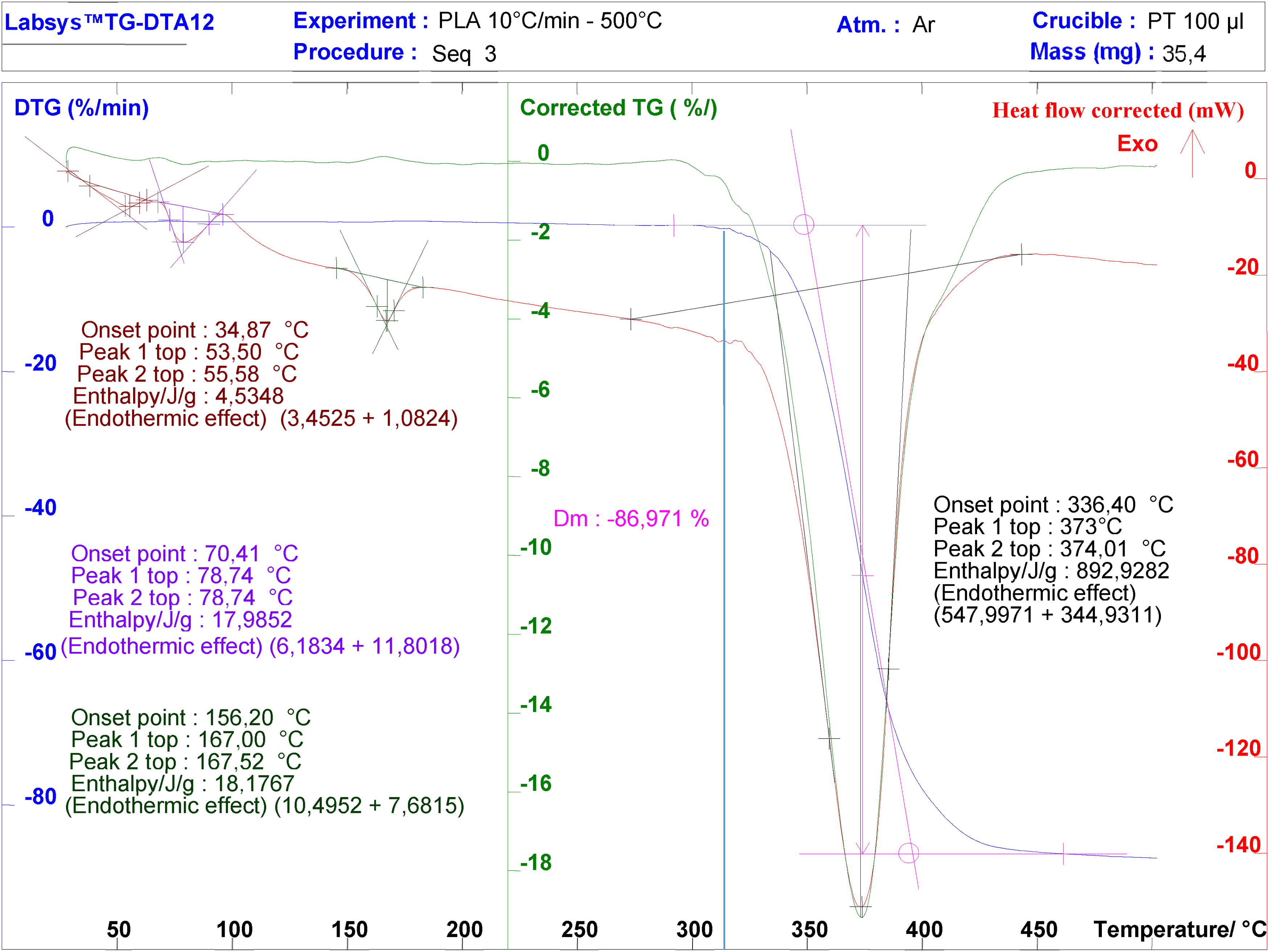
Thermogravimetric (TGA) spectrum of polylactic acid (PLA).
Results of DSC Analysis
In this work, a DSC test was first carried out on the studied 3D printing materials (PLA and TPU) to examine the possible phase changes after heating and cooling the filaments during the printing process. Figure 5 shows the DSC spectra of PLA and TPU obtained according to the considered protocol. Thermal transitions in amorphous TPU and semicrystalline PLA can be easily compared. As the temperature increases, both amorphous TPU and semicrystalline PLA go through a glass transition (Tg). Amorphous TPU does not exhibit any other phase transitions. However, semicrystalline PLA undergoes crystallization and melting. Figure 5 shows a shallow and convex bump (80 °C-100 °C) together with a small peak at 170 °C, which is observed over the first heating curve. The TPU filament consists of soft (SS) and hard (HS) segments following the formation of amorphous and crystalline structures upon cooling of the material. The wide peak observed within the temperature interval of 80-100 °C might correspond to a glass transition, but there is no obvious evidence of such a transition on this hard segment of TPU. Meanwhile, the resolved peak at T = 170 °C over the heating curve indicates the melting point of the TPU elastomer. Therefore, TPU exhibits excellent flexibility and glassy characteristics.34,35

Differential scanning calorimetry (DSC) spectra of PLA and TPU according to the considered protocol (heating, cooling, and isotherm) with the first heating phase shown separately.
The DSC thermogram of PLA shows the same classic domains as those of a semicrystalline polymer. Thus, the glassy domain exists at temperatures below the glass transition temperatures (Tg ≈ 63 °C). The rubber domain lies between Tg and crystallization (Tc = 90 °C). Then, the semicrystalline domain appears between the Tc and melting peak (Tm = 165 °C), and finally, the liquid domain appears. The first cooling curve shows the recrystallization temperature at ∼60 °C. The second heating phase also showed that the crystallization and melting points of PLA were shifting to the left low-temperature side. 36
Results of DMA Characterization
Figures 6 and 7 show the DMA thermograms of PLA and TPU. Storage, Loss and Tangent Delta (Tan Delta (δ)) are presented in these figures for each 3D printing material. The storage function of PLA exhibits an excellent range of energy absorption characteristics. The first step in the storage modulus decreases at 65 °C because of the glass transition (Figure 6). The energy dissipation in the form of heat started at 65 °C and showed poor energy dissipation capability of PLA under dynamic loading conditions. At 65 °C, the melting enthalpy of PLA is responsible for heat absorption and tends to deform the material. Peaks in the Tan Delta (δ) of PLA indicate viscoelastic transitions or relaxation events at 74 °C, 100 °C, and 131 °C. The relatively higher storage modulus explains the rigid nature of PLA. 37
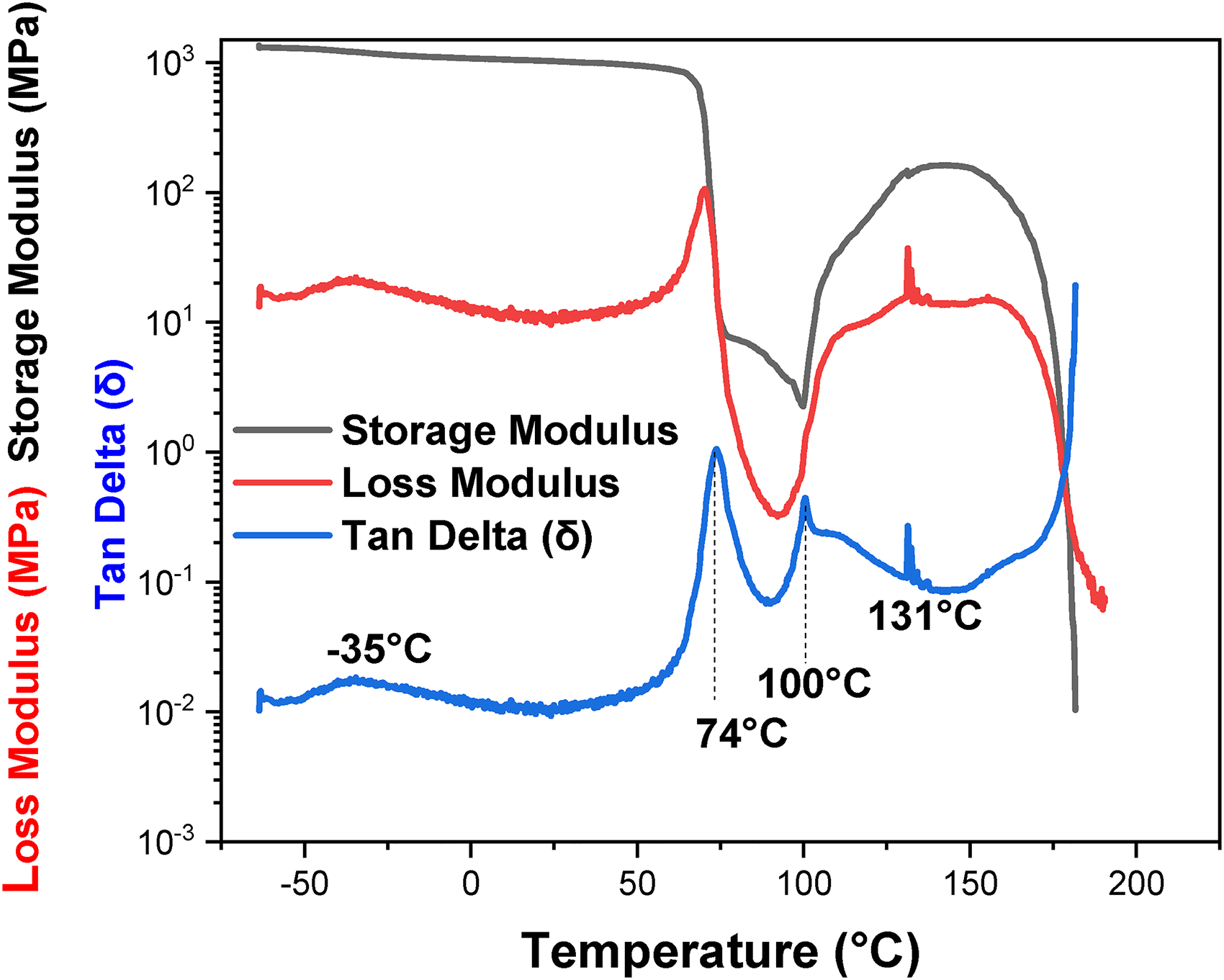
Dynamic mechanical analysis (DMA) spectra of PLA exhibiting the storage modulus, loss modulus, and Delta tangent.
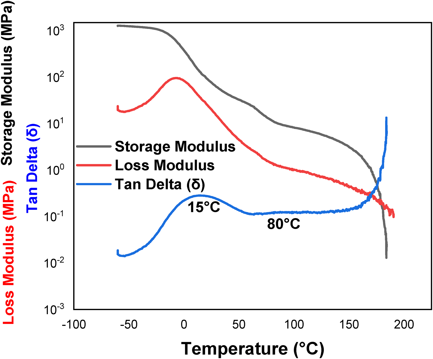
Dynamic mechanical analysis (DMA) spectra of the TPU with respect to the storage modulus, loss modulus, and Delta tangent.
The storage modulus, loss modulus, and tangent delta curves of the TPU with respect to temperature are displayed in Figure 7. The sharp decrease in the storage modulus indicates the characteristic glass transition temperature (Tg), which stems from the relaxation of the polymer chains throughout the thermal transition. The storage modulus of TPU was found to be of the same level as that of PLA until a temperature of 20 °C, after which it decreased strongly. With increasing temperature, the storage modulus of the TPU decreases more rapidly at higher temperatures. TPU exhibits glassy and viscoelastic transitions or relaxation events in the hard domain at 15 °C and ∼80 °C. The Tan Delta (δ) curve is the indication of vibration damping and acoustic properties. Accordingly, diatomite particles were used to give the TPU elastomer resistance to vibration. 38
Metrology Accuracy
The checked parameters presented in Table 3 are for an infill of 100%. The checked values on the printed bolus demonstrate that the printing process faithfully reproduces the geometrical details and dimensions specified in the design phase. Generally, the printed boluses, as in our cases, well matched the planned 3D models with high material uniformity. 39 Both PLA and TPU 3D-printed materials presented optimum printing performances in terms of dimension, CT number (HU), and density.
Metrology Testing Results.

Dosimetric Response Verification by TL Dosimetry
Figure 8 shows the reference PDDs and point doses measured by TL dosimetry at different depths (0, 14, and 28 mm) of the printed material. Taking into account the slight difference in the mass density between water and printing materials (PLA and TPU), the measured point doses exhibit conformal responses of the 2 materials for the 2 cases of treatment beams: x-rays and electrons. With respect to their densities, the measured relative point doses conform to those of water. The observed difference in doses is related to the difference in densities between water and printing materials (+13% for PLA and +3% for TPU). For a printing infill of 100%, the obtained data for the 2 3D printing materials (PLA and TPU) can be introduced into the TPS for dose calculation with an accurate equivalent thickness to that of human tissue.

Reference PDDs of water and measured point doses at different depths (0, 14 and 28 mm) for x-ray 6 MV photons and 12 MeV electrons of TPU (left) and PLA (right).
Hounsfield Unit Verification
Figure 9 elucidates the impact of infill on the HU of CT slices for TPU. The obtained results show the linear dependence of the HU on the variation in the infill level. Thus, by varying the infill level, several equivalent tissues can be obtained for even more specific applications of boluses manufactured by 3D printing. PLA exhibits similar behavior with specific HUs.

CT slice (right) and HU variation as a function of TPU infill (left).
3D Printing Analysis of Surface Finish
The scanned surfaces with the corresponding line of profiles (diagonal) and surface profiles are shown in Figure 10. The standard deviation (SD) of the gray level was used as an indirect metric of roughness. The obtained results are SDPLA = 2.54 and SDTPU = 5.55. As shown in Figure 10, the surface finish with PLA is clearly better than that with TPU, although both are acceptable for the targeted application. The obtained surface and line profiles demonstrate good planeness of the final surface.

Characterization of the surface finish and roughness of the final printed TPU and PLA samples.
The surface roughness has a linear relationship with the layer thickness. Thinner layers ensure better surface roughness of the 3D-printed bolus. The layer thickness cannot be reduced indefinitely at the risk of a very long printing time. A compromise must be found between the layer thickness and printing time.
Biocompatibility and Safety of PLA and TPU
PLA is a bioactive thermoplastic made from corn starch or sugar cane by fermentation, chemical processing, and polymerization. It is well known as a biodegradable, nontoxic, nonallergic, antibacterial, and antimicrobial material. The use of PLA for radiotherapy bolus fabrication is safe and does not cause health issues. PLA products are biocompatible, nontoxic, and harmless to the human body after degradation in the body through metabolism. 40 PLA has a strong anti-mite effect and natural antibacterial properties, with an antibacterial rate of more than 95% for major types of bacteria. PLA and its copolymers have been in clinical use for many years and have been proven to be biocompatible and safe. TPU is also a non-toxic and non-allergic material that does not contain any chemical that can interfere with the endocrine and hormonal systems. It does not contain any dangerous ingredients. TPU is generally considered biocompatible and suitable for medical applications. TPU has been widely used in medical devices, such as catheters, surgical tools, and prosthetics. TPU is used in the medical industry for medical devices and healthcare products. It is a biocompatible material. On the market, there is TPU that perfectly meets the requirements for skin irritation and sensitization tests (ISO 10993-10). 41
Bolus Positioning Verification
CT scanning is used to check the correct positioning and wearing conditions of a radiotherapy bolus by providing detailed images of the patient's anatomy, which allows radiation oncologists and medical physicists to assess the bolus' placement and condition. Figures 11 and 12 show 2 cases of boluses (nose and cheek) that were tested in this study. In each figure, the initial bolus definition on the TPS, the created 3D model, the printed bolus placed on the Rando phantom, and the CT slice of the phantom with the bolus are presented. Thus, the created bolus geometry and patient anatomy, including the tumor and surrounding tissues, can be clearly and easily assessed. CT-scan slices were acquired with the bolus in place. CT scans are crucial for verifying the bolus' correct positioning. 39 Thus, the CT images with the initial design were compared to the final CT images with the placed bolus to ensure that the bolus was correctly positioned. 39 Both considered cases of Figures 10 and 11) show the optimal wearing conditions of the manufactured boluses. The boluses well cover the treatment area as planned and are in close contact with the patient's skin, with minimal and insignificant gaps or air cavities.

Nose bolus as designed, 3D modeled, printed, and placed on the Rando phantom and checked in terms of positioning and contact by CT scan.

Cheek bolus as designed, 3D modeled, printed, and placed on the Rando phantom and checked in terms of positioning and contact by CT scan.
Discussion
FTIR spectra of TPU and PLA provide valuable information that can be used to assess the 3D printing performance of PLA and TPU for radiotherapy bolus fabrication. FTIR analysis offers insights into the chemical and structural characteristics of these materials, which can indirectly influence their performance in 3D printing applications. FTIR spectra confirm the identity and purity of the PLA and TPU materials, and no drastic changes due to chemical degradation after 3D printing that could affect material performance or final use.
The TGA results demonstrate that TPU and PLA exhibit different thermal stability and decomposition behaviors, which can affect their processing and application in different fields. In this study, the decomposition temperatures observed for the 2 studied materials were significantly higher than the 3D printing temperatures of the studied materials. The goal of this study was to determine the temperature region in which PLA and TPU can be used. By analyzing the thermal stability and decomposition behaviors of TPU and PLA using TGA, their properties and potential applications can be better understood. Thus, according to the obtained results, both materials can be considered thermally stable within the considered printing temperature range (180 °C-230 °C).
DSC analysis provides valuable information about the thermal properties, including melting point, crystallinity, glass transition temperature, and degradation behavior of 3D printing materials. These insights are essential for optimizing printing parameters, ensuring the 3D printing quality, and selecting the right material for specific radiotherapy applications. The determined melting points of PLA and TPU are vital for determining the optimal printing temperature. If the melting points are significantly different. On DSC spectra, the higher crystallinity of PLA confirmed its rigidity and brittleness, whereas the lower crystallinity of TPU demonstrated improved flexibility. At the glass transition temperature (Tg), PLA starts to become more flexible and less brittle. Knowledge of the Tg is important for avoiding warping and maintaining dimensional stability during 3D printing. The glass transition of TPU is very low (<°0), allowing a more flexible behavior of the material at room temperature.
DMA allows us to determine the main viscoelastic properties of the studied materials to make decisions about material selection and 3D printing parameters. If radiotherapy application need a flexible bolus, a low energy-absorbing material with low storage modulus, moderate loss modulus, and tan δ values is required such as TPU. DMA is necessary, therefore, a powerful analysis technique for the development, selection, and quality control of materials is used in radiotherapy bolus fabrication. By characterizing the mechanical properties of 3D printing materials, researchers and medical professionals can ensure that the bolus conforms appropriately to the patient's anatomy, leading to more effective and comfortable radiotherapy treatment.
Metrology test results are critical for ensuring the safety and accuracy of treatment. The densities of the studied materials were within the acceptable range and close to the water range. The effective densities (1.17 (PLA) and 1.25 (TPU)) after bolus printing are suitable for effectively modulating radiation dose as a function of depth. The surface finish and quality of the 3D-printed boluses demonstrated that TPU is better than PLA due to its softness. A smooth and uniform surface is important for patient comfort and the fabricated bolus accuracy; any irregularities or roughness can affect the bolus’ performance. The dimensions of the 3D-printed bolus match well the intended dimensions and conform to the treatment plan. The measured HU conform to the measured effective mass densities of the studied materials and can be introduced into the TPS as new bolus data. Interpreting metrology test results for 3D-printed materials in radiotherapy bolus fabrication requires close attention to treatment plan specifications. Any discrepancies or issues should be addressed promptly to ensure the safety and efficacy of the radiotherapy. Additionally, it is essential to stay updated with the latest advancements in 3D printing materials and metrology techniques to continuously improve the quality of radiotherapy bolus fabrication.
The results of the dosimetrical characterization showed that the differences between the measured point doses of the 3D-printed materials and their equivalents observed on the reference PDDs using PW3 water phantom were within the differences in densities between 3D printing materials and water. This indicates that, when appropriate thickness adaptation is applied, PLA and TPU 3D-printed materials are dosimetrically suitable for surface application in radiotherapy as dose boluses. The adaptation of the thickness can be easily performed by the TPS by introducing the corresponding data of the effectively used material (volume density, electron density, etc).
HU variation as a function of the infill rate with its linear behavior is a promising property that allows the adaptation of the fabricated bolus for specific cases of radiotherapy where it needs to be equivalent to another material rather than water (bone, lung tissue, etc).
The tolerance requirements for surface finish can vary depending on the specific application and the preferences of the medical team. In some cases, a smoother surface may be desired for better conformity with the patient's anatomy, whereas in other cases, a slightly rougher surface may be acceptable. In general, a surface roughness of Ra 10-50 micrometers may be acceptable for boluses used in radiotherapy, depending on the specific requirements of the treatment. However, consulting with medical professionals and adhering to any regulatory standards or guidelines applicable to similar medical device manufacturing are advised. Additionally, validation tests and quality assurance procedures can help ensure that the 3D-printed boluses meet the necessary surface finish and tolerance requirements for safe and effective radiotherapy use.
Performing a biocompatibility test is important for determining whether a material or product is safe to use in contact with living tissue. Several methods are available for biocompatibility testing, and the specific test used will depend on the type of material being tested and its intended use. When fabricating radiotherapy boluses using TPU or PLA, it is essential to conduct clinical evaluations to assess the safety and performance of the radiotherapy boluses, including monitoring for any adverse reactions or skin irritation. Recent studies demonstrate and show that PLA and TPU can be safely used for radiotherapy bolus fabrication. PLA films were found to have excellent biocompatibility and no obvious toxicity in vivo. 42 PLA/n-BG nanocomposites were also found to be safe for healing processes such as bone tissue repair and avoiding microbial contamination. 43 If PLA properties are enhanced with modifications that can be made when mixed with other polymers, the treatment spectrum of diseases with PLA will be enlarged. 44 Indeed, Moghaddam et al claimed that PLA is toxic-free and can be used instead of wet gauze as a breast bolus for surface dose enhancement and dose uniformity improvement during breast intraoperative electron radiotherapy. 3 DeStefano et al showed in their study that PLA can be considered a good choice as a biomedical material and be a contributing biomaterial for the near future. 45 Zhao et al. demonstrated in their study that 3D printing can be implemented effectively in the clinical setting to create highly conformal boluses for photon and electron radiotherapy, as well as for surface brachytherapy. 46 3D printed bolus in postmastectomy was found by Robar et al to fit well with radiation therapy and contributes to reducing patient setup time when compared to standard vinyl gel sheet bolus. 7 A proposed workflow for radiotherapy bolus fabrication by Canters et al was found to be patient-friendly, safe, and ensure high-quality dose distributions. 47 Like PLA, TPU was also found to be a suitable material for constructing scaffolds with interesting properties for tracheal transplantation. 48 When mixed with PCL, TPU exhibits good miscibility, excellent biomechanical properties, and nontoxicity for esophageal stents fabricated by 3D printing. 49 Even when in contact with blood, TPU can be used to manufacture medical devices by 3D printing followed by gamma sterilization. 50 Biocompatible scaffolds can also be prepared from TPU and PLA blends, with many possible applications in tissue engineering. 51
The positioning test results indicate that the fabricated blouses well fit the received surfaces. Any discontinuity or air gap can lead to an unintended variation in the radiation dose. Based on the CT images with the bolus, treatment plan adjustments can be made if necessary. If the bolus is found to be slightly off position, the treatment plan can be modified to ensure that the desired radiation dose is delivered to the tumor while minimizing the dose to healthy tissues. A quality assurance process may be performed to further validate that the treatment plan accurately represents the bolus' impact on radiation dose distribution. CT scanning is thus an essential tool in radiotherapy for assessing the bolus' effectiveness in achieving the desired radiation dose distribution. It provides a clear and quantitative way to verify that the bolus is properly positioned and in good contact with the skin to achieve the intended treatment goals. This verification process helps ensure the accuracy and precision of radiation therapy and dose delivery while minimizing the risk of delivering excessive radiation to surrounding healthy tissues.
In summary, some 3D printing final quality criteria of the selected and studied 3D printing materials were qualitatively compared in Table 4.
Final 3D Printing Quality.

Finally, in the context of radiation therapy dose bolus fabrication, certain limitations can be identified. In the case of complex anatomical sites, additional post-processing steps may be necessary to improve the surface smoothness of the printed bolus. Some 3D printing boluses are time-consuming and costly, especially for personalized treatments requiring complex geometries. The need for skilled personnel, specialized equipment, and high-quality materials contributes to the overall expense. Another issue regarding the use of 3D printing boluses concerns regulatory approval. Depending on the jurisdiction, 3D-printed boluses may require regulatory approval before clinical use. Some patient-specific factors, such as skin condition, open wounds, body habitus, and treatment site irregularities, can pose challenges in accurately designing and fabricating 3D-printed boluses. Despite these limitations, ongoing research and technological advancements in materials science, 3D printing techniques, and software algorithms are continually improving the feasibility and efficacy of 3D printing in radiation therapy bolus fabrication.
Conclusions
3D modeling and printing technologies are powerful and promising alternatives to conventional techniques used for fabricating radiotherapy boluses. These technologies allow the fabrication of comfortable and accurate boluses that widely can achieve the objective of final use.
In this work, commercially available FDM 3D printing materials (TPU and PLA) were characterized and tested for use in the fabrication of some practical radiotherapy boluses. These boluses were initially tested using the anthropomorphic phantom “Rando” by considering reel cases of radiotherapy treatment. The obtained results clearly show that TPU has some advantages over PLA for the fabrication of radiotherapy boluses in terms of mechanical, thermal, metrology, and dose-response properties.
All the characterization and testing results are favorable toward the safe, comfortable and efficient use of the studied 3D printing materials for the fabrication of radiotherapy boluses. However, it is important to note that the specific application of these technologies for the fabrication of radiotherapy boluses requires close collaboration between scientists working on the development of biocompatible 3D printing materials and medical professionals to ensure that the materials from which the boluses are made meet the necessary requirements for radiotherapy applications. This study is part of this collaborative approach for generating new data on available 3D printing materials that can be used for targeted applications. This achievement will contribute to the imminent implementation of such technologies at the Department of Radiotherapy of the Fighting Against Cancer Medical Center of Sétif, Algeria.
For the final implementation of these technologies, the next step was the comparison of treatment plans with and without boluses in terms of effective dose delivery and dosimetric validation for different treatment cases.
Footnotes
Abbreviations
Acknowledgments
The principle investigator, Prof. F. Kharfi, and his research team would like to thank the Thematic Research Agency in Health and Life Sciences (ATRSSV) and the General Direction of Scientific Research and Technological Development (DGRSDT), the Algerian Higher Education and Scientific Research Ministry for the financial support received in the framework of this national research project.
Declaration of Conflicting Interests
The authors declared no potential conflicts of interest with respect to the research, authorship, and/or publication of this article.
Funding
The authors disclosed receipt of the following financial support for the research, authorship, and/or publication of this article: The research leading to these results received funding from the Thematic Research Agency in Health and Life Sciences (ATRSSV) and the General Direction of Scientific Research and Technological Development (DGRSDT), Algerian Higher Education and Scientific Research Ministry, in the framework of the national research project, under Grant Agreement No 03/18/DFPR/ATRSSV/22 of 01/03/2022.