
Abstract
Introduction
Ultrasound (US) imaging is performed in real time, and thus, it can monitor tumor status during radiotherapy in real time, making US-guided radiotherapy an important technical means of radiotherapy. During US-guided radiotherapy, the patient's body is subjected to irregular deformation of tissues due to pressure, possibly leading to changes in the location and morphology of the patient's tumor. Increased probe pressure may introduce errors in organ localization, thereby affecting the dose distribution. 1 In addition, the deformation hinders the accurate localization and geometric analysis of anatomical structures, and restricts the image registration. 2 When computed tomography (CT) is aligned with US, the amount of deformation among different modal volumes is proportional to the amount of required computational work. 3 Correcting US image deformation can solve the aforementioned problems and save alignment effort, improving clinical feasibility.
Flack et al 4 adopted a generic homogeneous representation of tissues, using finite elements to estimate deformation. However, most tissues and organs in the human body have inhomogeneous densities and their properties may vary from person to person. To address this shortcoming, Dahmani et al 5 applied a linear elastic biomechanical model to estimate the individualized mechanical parameters of tissues by using US deformation fields. However, differences exist among individual patients and the model is not applicable to radiotherapy scenarios that require the real-time acquisition of patient US images for deformation correction. Sun et al. 6 used an empirical regression model for pressure-based US image deformation to correct US images. This method can be used to correct the deformation of two-dimensional (2D) US images; however, processing time is long and clinical utility is poor.
In the current study, we propose a pixel displacement-based deformation correction method to correct a deformed US image (USdef) into a nondeformed US image (USrev) under optimal pressure. This method does not require obtaining the elastic characteristics of the local deformation area caused by the probe pressure, but only relies on the ultrasonic video stream during the process of the probe just contacting the body surface to reach the optimal pressure. During the CT imaging process, as the patient is not affected by the pressure of the US probe and the CT image is not deformed, CT is used as the gold standard to verify the effectiveness of US deformation correction. Then, we align USdef and USrev separately with positioning CT image (CTstd), which is the gold standard for images, to evaluate the improvement brought by deformation correction on alignment accuracy by using quantitative metrics. Radiotherapy positioning and monitoring of tumor changes can be achieved by introducing CT images into dose calculation and ensuring the accuracy of US guidance.
Materials and Methods
Instrument Setup
A 6 degrees-of-freedom robot (RM65-6F, Realman, Beijing, China); a force/torque (F/T) sensor (Realman, Beijing, China); a CT system (Brilliance Big Bore CT, Philips, Amsterdam, the Netherlands), with a resolution of 1.0240 pixels per mm; a US image guidance system with a C5-2 convex array US probe (Clarity 310C00, Elekta, Stockholm, Sweden), with the same resolution as the CT system; a conventional color US machine (Acuson NX3, Siemens, Munich, Germany), with a resolution of 3.5702 pixels per mm, used for phantom US imaging. The F/T sensor has a range of 200 N and an accuracy of 0.1% FS, and is attached to the robotic flange. The robot can realize US-guided radiotherapy through autonomous movement or physician manipulation. The US image guidance system is capable of acquiring and tracking the position of the probe in space using a binocular stereo camera mounted on the ceiling of the treatment room. The system registers the coordinate system of the patient, US image, and CT image through the patient's body surface markers. The C5-2 convex array US probe used to obtain 2D US images is mounted on the probe's fixation fixture at the end of the robot. Each instrument is treated with radiation protection and can work normally in a radiotherapy environment.
Before the experiment, both the robot control system and Clarity US image guidance system were calibrated. The Clarity system is validated through calibration and Daily QC in Room Setup. By calibrating the F/T sensor integrated at the end through the robot's end flange, the force in the X, Y, Z, RX, RY, and RZ directions is compensated, resulting in more accurate readings of the force sensor. Additionally, we calibrate the coordinate systems of the robot base, robot end tool, and US probe imaging.
The original US images in the clarity US image guidance system are acquired by doctors following the instructions in the software interface. The system saves the US images in a file established for each patient and sends the patient's data to the Clarity server through a network interface. Exporting the US images from Clarity to the Monaco treatment planning system yields DICOM data. The radiation therapist can directly export DICOM data of CT and USdef from the Monaco system based on the patient ID. Subsequently, computer programming is implemented to achieve deformation correction of the US images from USdef to USrev, and ITK-SNAP software is utilized to register USrev and USdef with CT separately.
Optimal Pressure Acquisition
By observing the relationship between pressure and US imaging quality, the maximum amount of information that can be obtained from US images is collected when probe pressure is increased to a certain degree. US scanning is performed under the combined control of the robot's force and position, and optimal pressure is defined as the smallest pressure with the best image quality. In accordance with the effect of pressure on image quality, the optimal pressure is determined and US images are acquired under optimal pressure. Then, the pixel displacement of tissues and organs in US images caused by probe pressure is calculated. To characterize pressure-induced tissue deformations, force values are acquired in real time by using a force sensor at the end of the robot. When the probe exerts pressure on the body surface of a radiotherapy patient, the force value for each scanning position is set using Equation 1 and the US image of the corresponding pressure-induced deformation is acquired. The US image under optimal pressure is selected among n 2D US images obtained under different forces, Fi ∈ [Fstart, Fend], i = 1,…, n. Pressure is gradually increased through Fstep after a time interval tstep. Force spacing Fstep is chosen between 0.1 and 0.5 N because smaller change steps facilitate better observation of image changes, tracking of pixel displacement, and acquisition of optimal pressure.3,7 A small Fstep is used to track pixel motion at the beginning of the evaluation.

Deformation Correction
Soft tissue deformation correction in US images includes corrections based on local tissue features and overall images. Corner points are extracted using the Harris corner point detection algorithm, 8 and use corner points as a reference for selecting feature points. Overall and local image deformation corrections are completed on the basis of the pixel displacement of the nearest pixel of the feature points. The basic idea of corner detection is to use a fixed window to slide along each direction on the image and compare the grayscale change of pixel points in the window before and after sliding. If there is a large grayscale change within the sliding window in any direction, the corner point is considered to exist in the window. Grayscale values typically change from the inside to the edge of human tissues and organs, and this image characteristic is used to extract feature points. As shown in Figure 1, Harris corner detection is performed on the image, and the parameters blocksize, ksize, and K are set to 2, 5, and 0.15, respectively. Subsequently, feature points are selected among the detected corner points, prioritizing overall deformation in the longitudinal direction and local deformation generated by pressure exerted on tissues and organs.

Obtain corner points and feature points through phantom. (A) Harris corner point detection. (B) Feature point selection. The ultrasound (US) scanning object is a CIRS female pelvic phantom 404A. In the above figure, the organs include the bladder, cervix, and rectum. Among them, the superficial organs of the bladder and cervix have a larger shape variable at the top, while the rectum is located at the bottom of the phantom, with a smaller shape variable.
The minimum output sum of squared error (MOSSE) correlation filtering target tracking algorithm 9 is used to track the tissues and organs to be corrected, and pixel displacement is calculated using the optical flow algorithm. The Lucas-Kanade (LK) optical flow algorithm 10 is utilized to estimate pixel displacement. The idea of applying the LK optical flow method is to acquire the US video stream during the process from when the probe first touches the body surface to the optimal pressure, and to find the point set of feature points used to calculate the pixel displacement in the US video stream corresponding to the point set in the next frame. It should be noted that this study approximates the pressure at the time when the probe first touches the body surface to zero. As shown in Figure 2, this algorithm is applied to perform pixel tracking of the US video stream obtained when optimal pressure is determined in accordance with Equation 1 to characterize tissue deformation by using pixel displacement.

The optical flow algorithm calculates the image pixel displacement within the detection range of phantom ultrasound (US) imaging. The blue border represents the detection range, the red dots represent the pixel feature points used for pixel selection reference, and the black dots represent the pixel points filtered based on local pixel intensity.
During US-guided radiotherapy, ensuring that the pixel grayscale values in the US image do not change significantly between consecutive frames is necessary. Acquisition time between adjacent frames is sufficiently short and tissue motion in the image is slow. Adjacent pixels exhibit similar motion between them, reflecting spatial coherence.
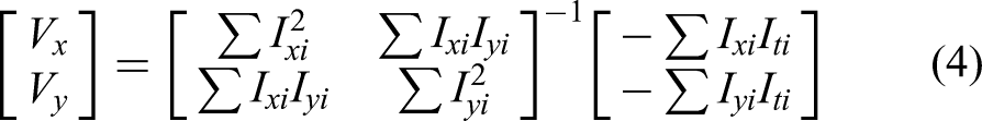
The LK optical flow algorithm calculates the optical flow (Vx, Vy) of a pixel point by considering the 3 directions of image x, y axes and time axis t, where Ix, Iy, and It are the differences of the image in (x, y, t) direction respectively, and the calculation formula is as follows:


Moving least squares (MLS) 11 is a technique that involves computing a weighted least squares metric to reconstruct continuous functions from disordered point samples. The MLS rigid deformation algorithm is an MLS-based method for image deformation correction, which can be employed for image fitting. The fundamental concept behind MLS rigid deformation is to use the weighted average of nearby points to maintain the local shape of the object while applying linear transformations, such as rotation and translation. By employing the least squares method to determine weights, the optimal fitting linear transformation can be obtained to minimize the distance between the deformation point and its original position, enabling smooth and continuous object deformation without introducing any significant distortion or stretching. This means that deformation correction is carried out while ensuring that the US image is not distorted. For images requiring rigid transformation, coordinate adjustments are applied to the pixel points obtained from the reference feature points to achieve image transformation. Specifically, USdef is reconstructed using a set of pixel points through rigid transformation to obtain USrev. The feature points are selected by filtering out some corner points extracted by the Harris algorithm at the end frame of the US video stream, and their nearest neighbor pixels are used for pixel selection. The overall and local pixel displacement of the image is calculated based on the position changes of the pixels in the US video stream, and the pixel displacement generated by the position changes is utilized for deformation correction.
Image Alignment
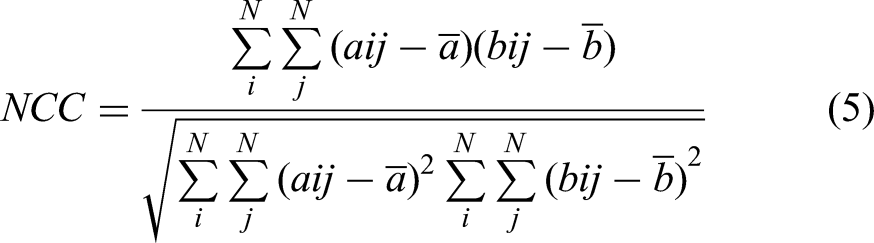
In order to ensure the quality of image registration, the optimal contact force acquisition method proposed in this study is used to obtain the ultrasonic video stream at the scanning position, record the contact force value during the scanning process and the corresponding USdef image, and convert USdef to USrev through the deformation correction method. Select the image combination with effective information and good imaging quality from the CT, USdef, and USrev image combinations corresponding to each spatial position for registration. The image registration tool is ITK-SNAP software. It should be noted that the original USdef and CT images corresponding to spatial positions are obtained by the spatial alignment function in the Clarity system. The normalized correlation coefficient (NCC) is applied to evaluate image alignment accuracy.
12
The NCC equation is as follows:
Results
In this study, the clinical feasibility of the developed method was verified through a somatic model and real-case experiments. Phantom experiments were performed using the CIRS female pelvic phantom 404A, which is a tissue-equivalent phantom that contains a uterus, a bladder, and a rectum. It is made of Zerdine® gel preparation to enhance realism by simulating the US contrast between the pelvis and background tissues. The volunteer experiment was performed on 12 patients who were undergoing radiotherapy for cancer, and all patients were informed and have agreed to participate in the volunteer experiment. To ensure imaging quality, a coupling agent was uniformly applied onto the surface of the phantom and the patient's body surface during US scanning.
In the phantom experiment, USrev was compared with the real invisible US image (USgt) obtained when the phantom was submerged in water without probe pressure. The correction error was calculated by the corresponding points between the 2, and the overall average correction error of the image was 1.0944 mm. By locally aligning USrev with CTstd, the average local correction error generated by tissues and organs is 0.7388 mm. As shown in Figure 3B, the thickness of the surface fat layer of USrev is uniform, and the shape of the internal organs conforms to the anatomical structure. The USdef, USrev, and USgt of the phantom were aligned with CTstd, and the effect of image deformation on the alignment results was analyzed. The alignment results of USgt and CTstd were used as the alignment standard, and the accuracy of the alignment of USdef and USrev with CTstd was evaluated using NCC. As shown in Figure 4, the aligned images were divided into 9 regions, and the image alignment accuracies of different image regions are provided in Table 1. The average NCC values were 0.6764 and 0.9016, with an average alignment accuracy improvement of 0.2252.

Phantom US image deformation correction. (A) Pre-correction of US image USdef. (B) Post-correction of US image USrev.

Regional distribution for evaluating image alignment accuracies.
NCC Evaluates the Registration Accuracy of Phantom US and CT.
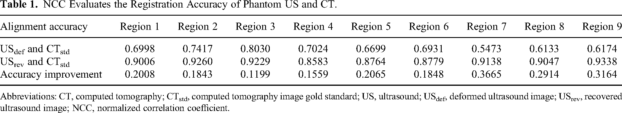
Abbreviations: CT, computed tomography; CTstd, computed tomography image gold standard; US, ultrasound; USdef, deformed ultrasound image; USrev, recovered ultrasound image; NCC, normalized correlation coefficient.
In the preradiotherapy simulated positioning stage, the patient was first positioned using a laser positioning device. Then, CT images of the patient's positioning were taken, followed by the acquisition of US images of the patient by using the Clarity US system. Finally, the CT images were aligned with the US images. The results of one volunteer experiment are presented in Figure 5. The bladder, which had a more evident deformation among the tissues and organs, was used as the research object to verify deformation correction performance. The bladder contours in USdef, USrev, and CTstd were manually outlined. Figure 5A and D shows the before and after correction images. Figure 5B and E shows the bladder contours before and after correction. Figure 5C depicts the required pixel feature points for deformation correction. Figure 5F illustrates the comparison of bladder contours in the USdef, USrev, and CTstd images. Figure 6 presents the alignment results of USdef and USrev with CTstd.

Deformation correction for the real cases. The blue line is the USdef bladder contour. The yellow line is the USrev bladder contour. The red line is the CTstd bladder contour. (A) US image USdef. (B) Bladder contour in USdef. (C) Pixel feature points are required for deformation correction. (D) US image USrev. (E) Bladder contour in USrev. (F) Bladder contour in USdef, USrev, and CTstd bladder contour comparison.

US and CT image alignment results. The orange line shows the bladder contour of the US image. The red line shows the bladder contour of the CT image. (A) USdef and CTstd. (B) USrev and CTstd.
The volunteer experiment utilized the method outlined above to conduct deformation correction through ultrasonic video streams of 12 patients. The baseline information of the patients was shown in Table 2. The linear distance between corresponding points in CT and USrev images was used to verify the range and mean absolute error (MAE) of correction error, and to analyze any instances of undercorrection or overcorrection. Undercorrection was considered negative, and overcorrection was considered positive. Figure 7 presents the results of the correction error analysis, which indicated a correction error range of −1.7525 to 1.5685 mm for all data, and a MAE of 0.8612 mm. Additionally, NCC was employed to assess the enhancement of registration accuracy in 12 patients, both before and after deformation correction, to demonstrate the efficacy of the proposed approach. The US image that has undergone artificial deformation correction by a senior chief physician and was consistent with the anatomical structure of CT tissues and organs, and has a uniform distribution of fat layers on the surface of the probe contact surface, was considered as the pseudo-USgt. The results of the registration between pseudo-USgt and CT served as the accuracy reference standards. Figure 8 depicts the evaluation results, indicating an improvement range of registration accuracy between 0.1232 and 0.2476.

Analysis of deformation correction errors in volunteer experiments.

Evaluating the registration accuracy of US and CT in volunteer experiments through NCC.
The Baseline Information of the Patients.

Discussion
Compared with other examination methods, US does not use radiation, has a short scanning time, and can be performed in real time. The use of US-guided radiotherapy techniques can save patients from additional exposure to radiation and improve the quality of soft tissue imaging. However, tissues and organs are susceptible to deformation due to probe pressure during US imaging. Deformation correction aims to render US tissue structures in their uncompressed biomechanical state to provide more accurate shape measurements or as a source of data for a geometric comparison with CT in radiotherapy. 13 Several USrev results that contained valid information and were corrected for image deformation were selected and aligned with CT slices at the corresponding locations to verify the feasibility of applying the described deformation correction method to US-guided radiotherapy.
The use of US-guided radiotherapy can improve the quality of soft tissue imaging, reduce positional errors, and avoid additional exposure to radiation of the patient. 14 Cabe et al 15 compared CT and CT/transperineal US images and found that aligning US images to CT images significantly improved the precision and accuracy of prostate contours. To evaluate the effect of image deformation on the alignment results, USdef and USrev were aligned with CT separately. From the experimental result, the alignment effect of USrev and CT registration was better than USdef, indicating that image deformation correction can improve the accuracy of US-guided radiotherapy, due to no deformation observed in either the USrev or CT images, and the relative positions of tissues and organs were unchanged. NCC can effectively evaluate image alignment accuracy. From the data in Table 1, image alignment accuracy was improved in upper regions 1, 2, and 3 and central regions 4, 5, and 6 after deformation correction. This result was largely due to the presence of more local tissue and organ deformations in this region. The correction accuracy in lower regions 7, 8, and 9 of the image was significantly improved due to the huge overall longitudinal pixel displacement of the image before and after correction because of pressure deformation and the lack of information at the bottom of the initial image, resulting in poor alignment. The analysis of deformation correction errors and evaluation of registration accuracy improvement in volunteer experiments have confirmed the effectiveness and universality of the proposed method, which is suitable for the deformation correction of US images in general situations. However, the correction errors remain substantial, and there is still significant potential for enhancing registration accuracy. The response to the pressure applied by the probe tended to vary for different individuals and scanning positions with varying tissue stiffness. Various factors should be fully considered during deformation correction, and more targeted processing can be used to improve correction performance. Notably, various sources of deformation that may occur during scanning, such as respiratory motion and in vivo tissue motion, must also be considered in clinical applications.
Future work will include the design of pixel displacement estimation models for local and global applications and the collection of various types of information from elastic tissues; further validation of the effect of image deformation on alignment results; exploration of potential clinical applications of deformation correction techniques; and completion of the prospective validation of clinical patients to collect information on the magnitude of respiratory motion, body tissue stiffness, and other information useful for assessing tumor deformation in US images. In this work, we propose a pixel-based correction technique for the clinical application of US-guided radiotherapy.
In summary, the pixel displacement-based deformation correction method proposed in this study can effectively correct image deformation. Compared with the initial US image, the deformation-corrected US image is more favorable for US-guided radiotherapy.
Conclusion
We propose a pixel displacement-based nondeformed US image production method that can solve the limitation of image deformation on image alignment in US-guided radiotherapy to achieve the fusion of nondeformed US images with CT images to guide radiotherapy. Compared with USdef, the alignment results of USrev with CT are better. The method uses the pixel displacement calculated by the LK optical flow algorithm with the deformed image and the image gold standard local overlap approach as the key factor for correcting deformation. By acquiring overall and local pixel displacements, the image is quickly corrected to an approximate nondeformed state. In this study, excellent correction results were obtained in the phantom and real-case experiments. In addition, the proposed method for deformation correction under the optimal contact forces of tissues and organs can be extended to other application scenarios of image deformation correction. The method described in this paper can enable further techniques, such as multimodal image-guided radiotherapy.
Footnotes
Abbreviations
Availability of Supporting Data
The data underlying this article cannot be shared publicly due to the involvement of patient personal privacy. The data will be shared on reasonable request with the corresponding author.
Declaration of Conflicting Interests
The author(s) declared no potential conflicts of interest with respect to the research, authorship, and/or publication of this article.
Funding
The author(s) disclosed receipt of the following financial support for the research, authorship, and/or publication of this article: This study was supported in part by grants from the National Natural Science Foundation of China (62371243), Jiangsu Provincial Medical Key Discipline Construction Unit (Oncology Therapeutics (Radiotherapy)) (JSDW202237), Social Development Project of Jiangsu Provincial Key Research & Development Plan (BE2022720) and General Project of Jiangsu Provincial Health Commission (M2020006).
Ethical Approval and Consent to Participate
The experimental protocol was established, according to the ethical guidelines of the Helsinki Declaration and was approved by the ethics committee of the Affiliated Changzhou No.2 People's Hospital of Nanjing Medical University (approval number: [2020]KY154-01) and waived the requirement for written informed consent from patients.