
Abstract
Background:
Palliation of advanced disease using radiotherapy can create difficult clinical situations where standard computed tomography simulation and immobilization techniques are not feasible. We developed a linear accelerator-based radiotherapy simulation technique using nonstandard patient positioning for head and neck palliation using on-board kilovoltage cone-beam computed tomography for 3-D volumetric planning and rapid treatment. Material and Methods: We proved cone-beam computed tomography simulation feasibility for semi-upright patient positioning using an anthropomorphic phantom on a clinical Elekta-Synergy linear accelerator. Cone-beam computed tomography imaging parameters were optimized for high-resolution image reconstruction and to ensure mechanical clearance. The patient was simulated using a cone-beam computed tomography–based approach and the cone-beam computed tomography digital imaging and communications in medicine file was imported to the treatment planning software to generate radiotherapy target volumes. Rapid planning was achieved by using a 3-level bulk density correction for air, soft tissue, and bone set at 0, 1.0, and 1.4 g/cm3, respectively.
Results:
Patient volumetric imaging was obtained through cone-beam computed tomography simulation and treatment was delivered as planned without incident. Bulk density corrections were verified against conventionally simulated patients where differences were less than 1%. Conclusion: We successfully developed and employed a semi-upright kilovoltage cone-beam computed tomography–based head and neck simulation and treatment planning method for 3-D conformal radiotherapy delivery. This approach provides 3-D documentation of the radiotherapy plan and allows tabulation of quantitative spatial dose information which is valuable if additional palliative treatments are needed in the future. This is a potentially valuable technique that has broad clinical applicability for benign and palliative treatments across multiple disease sites—particularly where standard supine simulation and immobilization techniques are not possible.
Keywords
Introduction
The delivery of radiotherapy (RT) treatment plans has become increasingly complex with the transition from 2-dimensional (2-D) to 3-dimensional (3-D) treatment planning and delivery. After consultation and patient consent to treatment, the modern RT workflow involves patient simulation using computed tomography (CT) with immobilization devices for reproducible treatment delivery, treatment planning, plan quality assurance and verification, verification of on-treatment setup/patient positioning, and treatment delivery. Due to the number of steps involved in the delivery of a basic RT plan, and the overall complexity of care, RT plan generation often takes several days—or even weeks for intensity-modulated radiation therapy (IMRT). In the definitive (curative) treatment setting, this projected time frame may be acceptable; however, in the palliative setting where symptom control is paramount, this delay is less than ideal. Furthermore, palliation of advanced disease can be challenging and consideration must be given to the feasibility of standard CT simulation and immobilization techniques in medically complex and often fragile patients.
Herein, we describe an on-board kilovoltage (kV)-based cone-beam CT (CBCT) RT simulation technique for 3-D image acquisition, conformal treatment planning, and treatment of the head and neck in the palliative setting. This technique has broad clinical application to any patient unable to fit through a wide-bore CT machine, tolerate standard supine simulation and immobilization, or in an emergent situation where 3-D imaging is preferable in a “scan, plan, treat” clinical workflow. 1,2 Additionally, this approach is readily applicable in clinical practice and does not require special equipment or expertise to be employed.
Written informed consent was obtained from the patient, and no identifying information appears in this article. No institutional review board approval was required as no investigational treatment was administered.
Materials and Methods
Example Case
A 36-year-old woman with progressive, late-stage amyotrophic lateral sclerosis (ALS) was evaluated for medically refractory sialorrhea causing aspiration and affecting her quality of life (QoL). 3,4 At the time of consultation, the patient had severe drooling, with a Sialorrhea Severity Score (SSS) of 7, and was interested in RT for palliation. 5 The patient was unable to safely lie flat due to aspiration risk with her late-stage ALS when standard CT simulation was attempted. Given the anatomic location of the target (parotid and submandibular glands), 3-D–based planning could improve oral cavity and central nervous system sparing. Therefore, we developed a semi-upright head and neck CBCT simulation method on a clinical Elekta linear accelerator to obtain 3-D axial imaging for RT planning and treatment.
Cone-Beam Computed Tomography
Simulation feasibility
Prior to patient CBCT simulation, a feasibility study was conducted on the Elekta-Synergy linear accelerator used for treatment with an Alderson RANDO anthropomorphic phantom to determine the ideal CBCT parameter settings. Various gantry and couch positions were tested to ensure mechanical clearance and to meet the minimum 200° CBCT arc rotation for high-resolution 3-D image reconstruction using the manufacturers’ reconstruction algorithm (Figure 1). A customized CBCT image acquisition protocol was optimized for tight spatial clearance tolerance and for image quality by adjusting the limits of gantry rotation, gantry speed, and image reconstruction quality. 6 -8 The final machine CBCT settings are shown in Table 1.
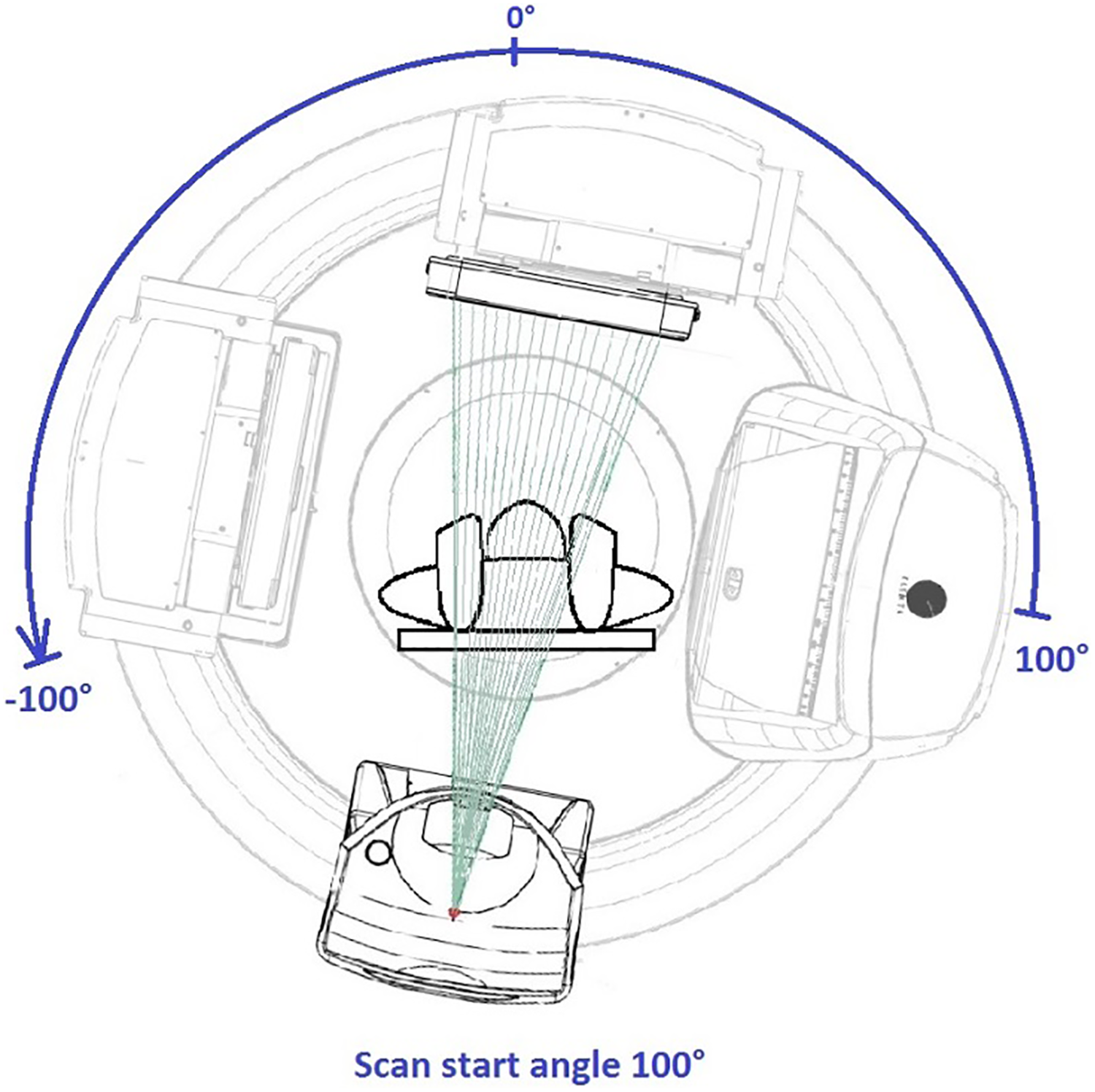
A 200 kV CBCT simulation on a linear accelerator treatment machine. CBCT indicates cone-beam computed tomography.
Elekta System Settings Used for CBCT Simulation.a
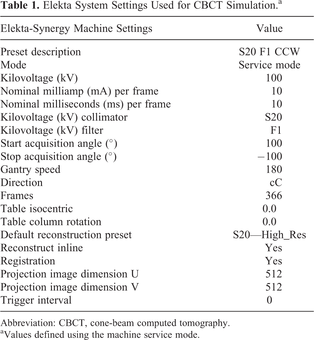
Abbreviation: CBCT, cone-beam computed tomography.
aValues defined using the machine service mode.
Patient simulation
The patient’s inability to protect her airway given her copious secretions or breathe comfortably at lower inclination angles due to her disease process was the main reason that conventional CT simulation could be not employed, and this technique was developed. The patient was placed on the Elekta treatment machine and was simulated in the lowest semi-upright position she could tolerate using a breast board indexed to the couch at “A.” A Vac-Lok cushion was used to further elevate the patient’s thorax to a 65° incline as measured by a digital goniometer and immobilize the thorax, neck, and head. Slight neck extension was achieved using a towel roll and straps were secured to the couch (Figure 2). A washcloth was placed in the oral cavity per the patient’s routine drooling management. Due to patient anxiety, in lieu of thermoplastic mask immobilization, a forehead strap was used to minimize head rotation. Reproducibility was aided using midline and lateral tattoos.

Patient positioning using breast board and Vac-Lok cushion for elevation of the head, neck, and thorax.
Cone-Beam Computed Tomography Treatment Planning
Acquired CBCT digital imaging and communications in medicine images were imported to Philips Pinnacle 9.10 treatment planning software to generate treatment volumes defined as the parotid and submandibular glands, beam placement, and for inverse treatment planning. Treatment planning was optimized by using 12 and 15 MeV electrons to the left and right parotids and submandibular glands, respectively. The radiation fields encompassed the submandibular gland and inferior two-thirds of the parotid gland while minimizing dose to the oral cavity, spine, or brain. En face electron fields were chosen similar to published series. 9 Rapid planning was achieved by bulk tissue density correction, with air set at 0 g/cm3, soft tissue set at 1.0 g/cm3, and bone set at 1.4 g/cm3. Bulk density override was achieved via manual segmentation of the patient’s anatomy (air, soft tissue, bone) in the treatment area and assigning a physical density to each region. Threshold-based segmentation was not used due to the limited treatment field size; however, this approach is valid and feasible for larger treatment areas. The bone electron bulk density correction was verified using CT images acquired from patients simulated on a Philips 16-slice Brilliance Big Bore CT scanner. Ten mandibular electron density measurements were taken from various mandibular areas for 10 patients and differences were less than 1% from the 1.4 g/cm3 value. As part of a staged approach, the treatment to the left parotid and submandibular gland was performed first, followed by the right side 8 months later. A composite dose plan was then produced to document the total delivered dose to the targets and organs at risk (OARs; Figure 3).
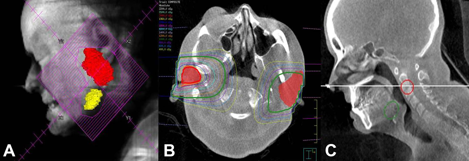
A, “Beam’s eye” reconstruction showing the RT field generated from the CBCT planning scan. B, Axial imaging showing the bilateral parotid glands (red color wash) with the left (12 MeV) and right (15 MeV) en face electron isodose lines for treatment. C, Corresponding sagittal view. CBCT indicates cone-beam computed tomography; RT, radiotherapy.
Results
Unilateral left salivary gland RT was successfully administered using 12 MeV en face electrons to 20 Gy in 4 fractions delivered twice per week over 2 weeks. Accurate treatment setup was verified using patient tattoos, clinical light field projection, 2-D kV setup verification, and megavoltage (MV) port image with the electron cutout in place (Figure 4).

Digitally reconstructed radiograph showing the treatment field (A) and MV port (B) confirming patient positioning.
In this case, the use of electrons was advantageous as it allowed for collimator rotation to adjust for neck extension/flexion prior to each fraction. Two weeks after unilateral RT, the patient noticed improvement in sialorrhea, with an SSS of 2, and was able to decrease utilization of her anticholinergic medications. She denied any acute mucositis and developed minimal skin reaction. A dose–volume histogram (DVH) of delivered dose to the left salivary glands (parotid and submandibular) planning target volume (PTV) and OAR is shown in Figure 5A.

Dose–volume histogram (DVH) showing doses to target structures and organs at risk from treatment of the left (A) and right (B) salivary gland (parotid and submandibular) planning target volumes (PTV). A composite DVH is shown in C. Doses are shown in the follow colors: Parotid is shown in red (left) and light green (right), submandibular gland is shown in pink (left) and dark green (right), spinal canal is shown in teal, and inner ear (cochlea plus semicircular canals) is shown in orange (left) and blue (right). Note that the left parotid (red) and submandibular gland (pink) DVH curves are beneath the left inner ear curve (orange) in (B).
Eight months after the initial treatment, the patient’s sialorrhea increased and the right salivary glands were then treated using 15 MeV en face electrons. A DVH of delivered dose to the right salivary glands (parotid and submandibular) PTV and OAR is shown in Figure 5B. After completion of 2 fractions (10 Gy), the SSS stabilized at 4 and additional fractions were deferred. Cone-beam computed tomography simulation and acquisition of 3-D volumetric imaging allowed for rapid generation of plan composite doses to PTV and OAR structures. A composite RT plan DVH for treatment of the left and right salivary glands is shown in Figure 5C. The patient experienced no mucositis or skin reaction. After 3 months of clinical follow-up, SSS was stable at 4, and there was patient-reported improvement in QoL.
Discussion
Palliative RT in patients unable to tolerate supine CT simulation or treatment can be challenging whether in cases of malignant or nonmalignant disease. Other groups have demonstrated the feasibility of using a vertical CT scanner for simulation of patients unable to tolerate the supine position. 10 However, space and resource limitations make this approach impractical for widespread use. This report describes the practical clinical application of kV CBCT-based head and neck simulation and treatment planning method using a 200° CBCT arc on an Elekta clinical linear accelerator for 3-D conformal RT delivery for a patient treated in a reproducible, semi-upright position.
Although rudimentary 2-D clinical setup techniques could be employed in these palliative situations, our approach minimizes the chance of adverse treatment-related sequel to adjacent OAR by providing enhanced 3-D anatomic information. 11 Cone-beam computed tomography image guidance provides high-contrast spatial resolution (1-2 mm) and stable image generation 12,13 with acceptable dose exposure, 14 making it suitable for image acquisition for treatment planning. Furthermore, this CBCT approach provides 3-D documentation of the RT plan and allows for easy and rapid calculation of composite quantitative spatial dose information, which may be valuable if additional palliative RT treatments are needed in the future (Figure 5C), as in this case.
Although this CBCT technique does provide additional anatomic detail over 2-D approaches, the density used for dosimetric calculation is manually overridden using 3-level air, bone, and soft tissue reference values. This density override map does not truly reflect the heterogeneity of head and neck structures; however, given the small field size and low plan inhomogeneity, Pinnacle’s electron model has been shown to agree within experimental uncertainties with measurements. 15 Pinnacle uses the Hogström pencil beam electron model where tissue inhomogeneity is corrected by assuming that linear stopping power of the material is independent of electron energy. 16 We determined that the dose using this approach was valid, and other studies have confirmed dosimetric feasibility using kV CBCT for treatment planning. 17,18
Although we tested and validated treatment with electrons for ease-of-treatment setup, if photons had been used, the 3-level CBCT density correction we used may not even need to be considered, with a simpler, water-only correction being adequate. The collapsed cone planning algorithm used by Pinnacle for high-energy (6 MV+) photons has shown less than 1% difference in monitor unit calculation and dose distribution for simple treatment setups (wedge pair, tangent/oblique, anterior/posterior, etc), and the treatment volume is assigned water density only. 19 A simplified bulk density correction could be=considered for treatment throughout the body 2 ; however, care should be exercised with this approach when there are large differences in adjacent tissue density, such as the oral cavity due to extensive surrounding bone and/or dental amalgam artifact, the spine 1 when lung is included due to lower lung density (electron to physical density conversion of approximately 0.3-0.4 g/cm3), 20,21 the low (true) pelvis due to extensive surrounding bone, and/or artifact from hip replacement(s).
Furthermore, patient-specific dose calculation and plan assessment has proven feasibility in the head and neck region and, using our approach, has valid for either malignant or benign processes. 22 For patients with bulky tumors who are expected to have large and/or rapid tumor response to palliative radiation, CBCT-based planning and dose assessment has been shown to be a rapid and highly accurate assessment of dose change. 23 In these patients, CBCT-based dose evaluation and RT reoptimization represents a rapid and ideal clinical decision aid to optimize patient treatment. Finally, standard CT simulation offers superior soft tissue contrast and density information, and patients who are able to tolerate conventional simulation should do so. However, for patients requiring palliation and are unable to tolerate standard supine simulation and immobilization techniques, this approach provides a valuable option as part of an efficient “scan, plan, treat” clinical workflow. 1,2
In conclusion, we successfully developed and employed a practical clinical application of kV CBCT-based head and neck simulation and treatment planning method for 3-D conformal RT delivery using nonstandard, semi-upright patient positioning. This approach also provides 3-D documentation of the RT plan and allows tabulation of quantitative spatial dose information, which is valuable if additional palliative treatments are needed in the future. This approach is readily applicable in clinical practice and does not require special equipment or expertise to be employed. Additionally, this technique has broad clinical applicability in the palliative setting across multiple disease sites—particularly where standard supine simulation or immobilization techniques are not possible.
Footnotes
Declaration of Conflicting Interests
The author(s) declared no potential conflicts of interest with respect to the research, authorship, and/or publication of this article.
Funding
The author(s) received no financial support for the research, authorship, and/or publication of this article.