
Abstract
Perforated panels (PP) and porous materials are often combined to achieve the excellent wide-band sound absorption effects. However, hardness, restricting structural change, unstable laminated structure and thickness limit the improvement of its acoustic performance. This paper puts forword a new composite fabric sound-absorbing material with a structure featuring inner periodic rigid PP units and outer flexible fabric design. The total area of PP had been decreased by 29% ∼ 54% in the new structure (FPP). Sound absorption coefficient and the specific acoustic impedance results showed that the new FPP absorber had the similar or the higher sound absorption peak value (>0.920) compared the laminated structure in the frequency range of 48 ∼ 1700 Hz. FPP absorbers with PP units size 7 ∼ 65 mm exhibit excellent half-absorption bandwidth (1185 ∼ 1312 Hz) in the frequency range of 48 ∼ 1700 Hz. The sound absorption peaks shift towards the lower frequencies by increasing the size of periodic PP unit. The new prediction model based on the equivalent circuit method has been established for predicting the sound absorption of the new structure. This work provides a new strategy for the broad application of acoustic PP or fiber material.
Keywords
1. Introduction
Noise control has become an important topic in acoustics, materials, mechanism, for improving the standard of living. Perforated panel (PP) and microperforated panel (MPP) are widely used as the sound absorption material. 1 The sound-absorbing mechanism of PP and MPP, which is typically backed by an air cavity and a rigid wall, is Helmholtz resonators absorption. 2 High sound absorption at specific frequency is the advantage of this kind of absorption. But the sound absorption in the other frequency band decreases quickly resulting in the narrow sound-absorbing frequency band. A number of studies have been carried out to broaden the absorption frequency band of PP and MPP, such as changing structure of the back cavity including depths, 3 configuration,4,5 multipled cavity,6,7 compositing backed with the porous materials,8,9 multi-layer PP or MPP,10,11 perforation shape. 12 Good sound absorption have been achieved in these studies, but it is difficult to processing and regulating the structure of absorber, and MPP are mostly metal materials with high cost.
Fabrics have lightweight, flexibility, thin, large fiber coverage, good structure design ability and low cost. According to Maa’s1,13 micro-perforated panel theory, the small internal pore diameter and the large area without pores are benefit for improving sound absorption of materials. Therefore, woven fabrics-as the sound-absorbing materials have been widely studied.14–16 These researches showed that fabrics have the weak sound absorption below frequency 1800 Hz.
Spatial absorbers of non-woven fabric with micro-perforated plate-like structure have good sound absorption performance. 17 The axial attenuation and sound absorption of MPP backed by fabric materials are enhanced.18,19 The integrated membrane-fabric material exhibits good sound absorption across a wide frequency range. 20 The compound structure composed of a perforated panel resonator and porous foam material showed good sound absorption at the low and middle frequency. The absorption mechanism is the resonance dissipation of perforated panel resonator, the energy capture of porous material and as well as the coupling effect of two materials. 9 In the above studies, the used space of absorbers are also relatively large.
PP will be divided into multiple small units, then periodically fill them into the flexible fiber frame in this paper. The sound absorption coefficients and the relative acoustic impedance of the new flexible frame fiber material with the small periodic PP units were analyzed.
2. Experimental details
2.1. Sample preparation
In this paper, hollow polyester yarn was used for preparation of flexible frame fiber material samples. The fineness of yarn is 10 S. Yarn is supplied by Shaoxing Xineng Textile Technology Co., Ltd. The perforated plates (PP) are supplied by Wuxi Yirongda Hardware Materials Co., Ltd.. The pore diameter and thickness of PP is 0.8 mm and 0.48 mm, respectively.
The fabric weaves with the periodic pocket units were designed. Then, the fiber fabric samples with PP units (FPP) were prepared after fabric weave design, yarn preparation, threading, and weaving process (see Figure 1(a)). The weaving process includes shedding, weft insertion, beating-up, PP units insertion, tack-up and let-off. The structure diagram of FPP sample and FPP absorber are shown in Figure 1(b) ∼ (f). Changing the fabric weave design, FPP samples with different size (65 mm, 32 mm, 19 mm, 7 mm) of pockets and PP units were prepared. The warp density and weft density of woven fabric is 232±3 root/10cm, 176±3 root/10cm, respectively. The parameters of all samples are listed in Table 1. Fabrication process, structure of FPP material, and the schematic diagram of FPP absorber. (a) Fabrication process of FPP material, (b) surface morphology diagram of FPP material, (c) sectional morphology diagram of FPP material, (d) flexibility of FPP material, (e) weave design diagram of FPP material, (f) schematic diagram of FPP absorber with air back cavity. The parameters of all samples. FPPN1 and FPPN2 means PP units facing the sound source and non-woven fabric units facing the sound source, respectively. F1, F2, F3 and F4 means fiber woven fabric with different pocket structural units. The size of pocket structural units is 1∼4mm larger than the size of PP units.

2.2. Thickness
The thickness of samples was measured on a YG141H digital fabric thickness tester (Quanzhou MeiBang Instrument Co., Ltd.) with 0.001 mm accuracy, according to ISO 5084: 1996 standard. 21 The pressure is 100 cN. The area of the presser foot is 100 mm2. The thickness value of samples are listed in Table 1. Each thickness value is the average value of five measurements taken at different positions of a sample.
2.3. Mass density
The mass density of samples was calculated according to the ratio of mass and area of fabric. Mass is measured by a balance. The mass density value of samples are listed in Table 1. Each value is the average value of five measurements for a sample.
2.4. The normal incident sound absorption parameters
The normal incident sound absorption coefficients and the relative surface impedance were assessed by using a two-microphone transfer-function method, according to ISO 10534-2 standard. The testing apparatus is SW4201 impedance tube with 10 cm inner diameter which is a part of a compete acoustic system SW4000 (BSWA Technique Company, China) (Figure 2). Sound absorption coefficients in the frequency range of 45 ∼ 1700 Hz were measured. In this paper, the temperature and humidity during sample testing is 25°C and 50%, respectively. The characteristic impedance of the air (a) Measurement setup for the normal incidence sound absorption coefficient and specific acoustic impedance, (b) installation of sample.
In this paper, the half-absorption bandwidth refers to the width of the frequency band in which the absorption coefficients on both sides of the absorption coefficient curve decrease to the half of their maximum value, with the resonance frequency as the center.
3. Results and discussions
3.1. Sound absorption property of the new FPP absorber
3.1.1. Sound absorption of new FPP absorber
In order to avoid interface delamination in PP/F lamination, the new PP and fiber fabric integrated structure materials (FPP) were fabricated in this paper. Figure 3(a)∼(d) show FPP material with different size of PP unit, and sound absorption are shown in Figure 4(a)∼(d). In Figure 4(a), F1/PP means sample F1 faces the sound source, and PP/F1 means PP faces the sound source during the sound absorption measurement of PP and fiber fabric lamination. Figure 4(b)∼(d) are the same as Figure 4(a). New FPP materials with different size of periodic units, (a) FPP1, (b) FPP2, (c) FPP3, (d) FPP4. Comparisons of sound absorption of new FPP absorbers and PP/F and F/PP laminate: (a) Sample FPP1, (b) sample FPP2, (c) sample FPP3, (d) sample FPP4.
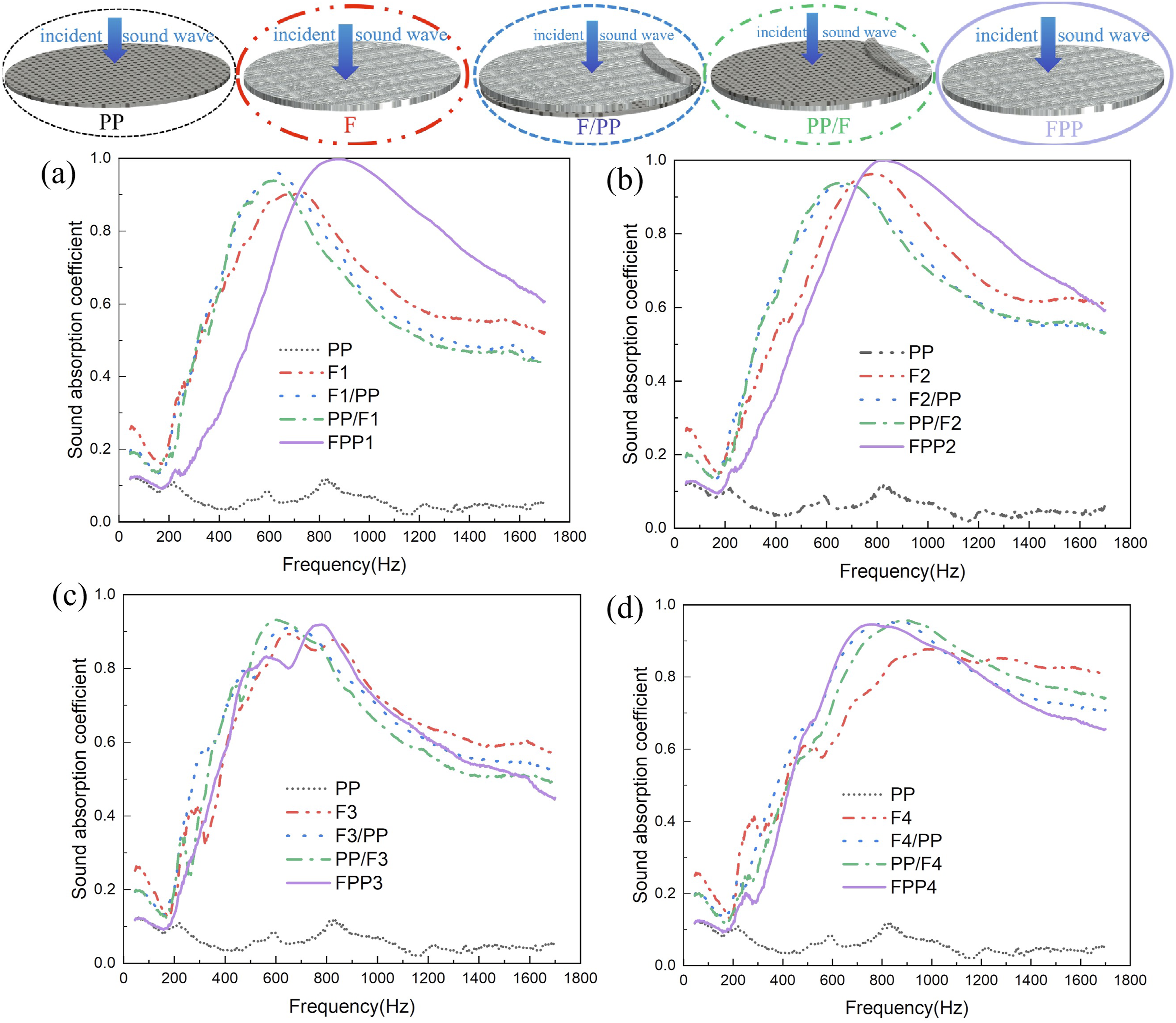
Comparisons of area of PP, maximum and average sound absorption coefficient (SAC) of FPP, F/PP, PP/F, F and PP.

The mechanism of this phenomena can be explained by the real part (specific acoustic resistance) and imaginary part (specific acoustic reactance) of the specific acoustic impedance in Figure 5(a) and (b). Figure 5(a) shows that compared to other samples, the specific acoustic resistance of FPP1 absorber is nearer to one line in the frequency range of 45∼1700 Hz. This means that the acoustic resistance of FPP1 absorber is closer to the characteristic impedance of air and leads to the strong impedance matching with air which causes the less reflection of sound on the surface of FPP materials, resulting in the more the incident sound waves transmitting into material. Figure 5(b) shows that the specific acoustic reactance of FPP1 absorber is nearer to zero line above 875 Hz frequency. This means that the more loss of sound energy in the materials. The combination of two conditions leads to the higher peak value of sound absorption and the better sound absorption of FPP absorber above 875 Hz frequency.23,24 The real part and the image part of the specific acoustic impedance: (a) The real part, (b) the imaginary part (sample FPP1).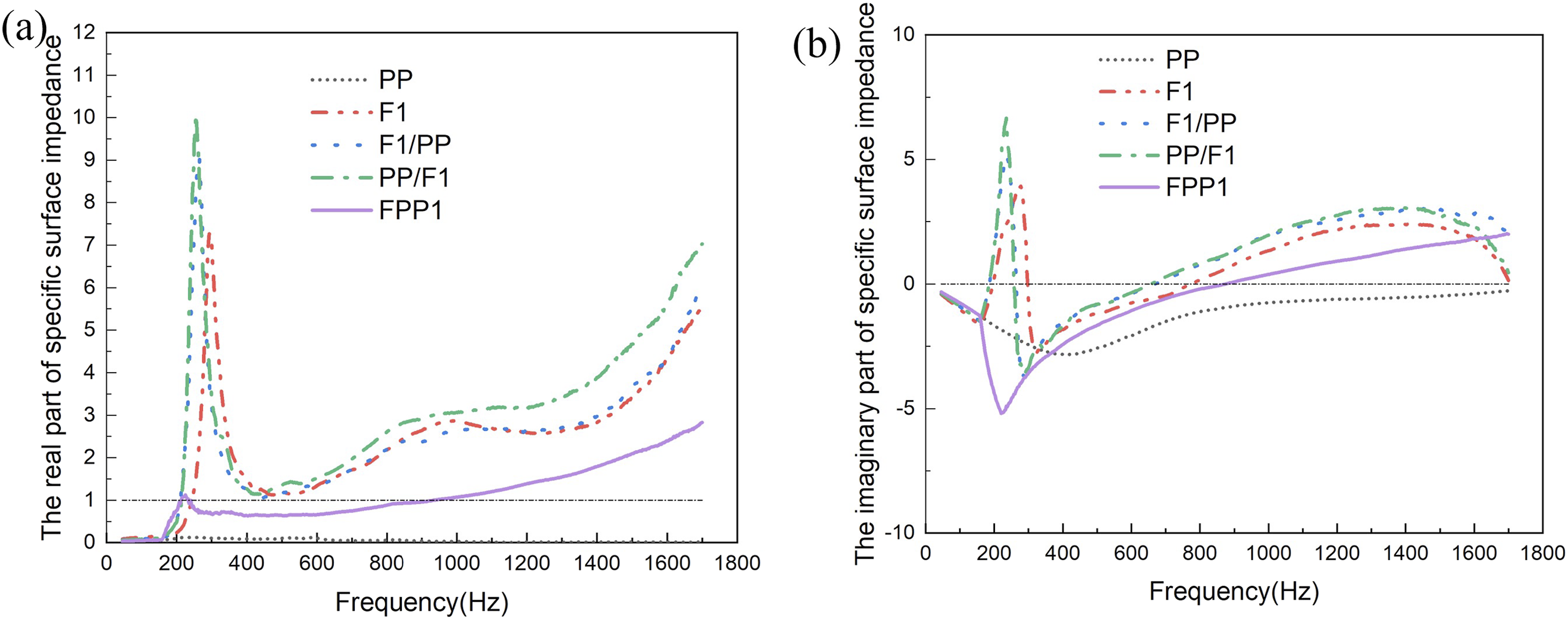
Figure 4(b) and (c) shows the same phenomenons as Figure 4(a). FPP absorbers with the smaller area of PP have the similar or greater sound absorption peak value. These phenomena can be explained by the specific acoustic impedance in Figures 6(a), (b), 7(a) and (b). The maximum SAC and average SAC of FPP4 absorbers slightly lower than those of F4 or F4/PP, PP/F4 laminated materials shown in Figure 4(d) and Table 2. The specific acoustic resistance and the specific acoustic reactance curves showed in Figure 8(a) and (b) indicate that the specific acoustic resistance of FPP4 further away from one line (the best resistance matching) than the above samples when the specific acoustic reactance of FPP4 close to zero line (location of the absorption peak), resulting in the less attenuation the sound energy. The real part and the image part of the specific acoustic impedance: (a) The real part, (b) the imaginary part (sample FPP2). The real part and the image part of the specific acoustic impedance: (a) The real part, (b) the imaginary part (sample FPP3). The real part and the image part of the specific acoustic impedance: (a) The real part, (b) the imaginary part (sample FPP4).


The sound absorption property of FPP absorber were further analyzed as shown in Figure 9. Figure 9(a) indicates that four FPP absorbers exhibit excellent half-absorption bandwidth 1185 ∼ 1312 Hz, and the proportion of sound absorption coefficient (SAC) points exceeding the half of the maximum absorption coefficient 72% ∼ 79% in the frequency range of 45 ∼ 1700 Hz. In addition, the sound absorption peak frequencies of FPP3 and FPP4 with the more number of PP unit are lower than those of FPP1 and FPP2 with the less number of PP unit. These can be analyzed from the imaginary part curves of the specific acoustic impedance of FPP absorbers as shown in Figure 9(c), the reactance of FPP absorber increases more quickly with the increasing of the number of PP unit which causes the reactance to reach to the zero line earlier, resulting in the lower sound absorption peak frequency. The sound absorption property of FPP absorber: (a) The half-absorption bandwidth, (b) the real part of specific acoustic impedance, (c) the imaginary part of specific acoustic impedance.
3.1.2. Effects of size of PP unit on sound absorption of FPP absorber
In order to study the effects of pp unit size on the sound absorption of new FPP material, sound absorption of FPP materials with different area of one PP unit were analyzed in Figures 10 and 11. FPP material samples with different area of one PP unit and sound absorption coefficient curves of FPP absorbers: (a) 65×65mm2, (b) 32×32mm2, (c) 19×19mm2, (d) 7×7mm2, (e) comparison of sound absorption of FPP samples. Comparisons of the real part and the image part of the relative surface impedance of FPP structure with different PP unit size: (a) The real part, (b) the imaginary part.
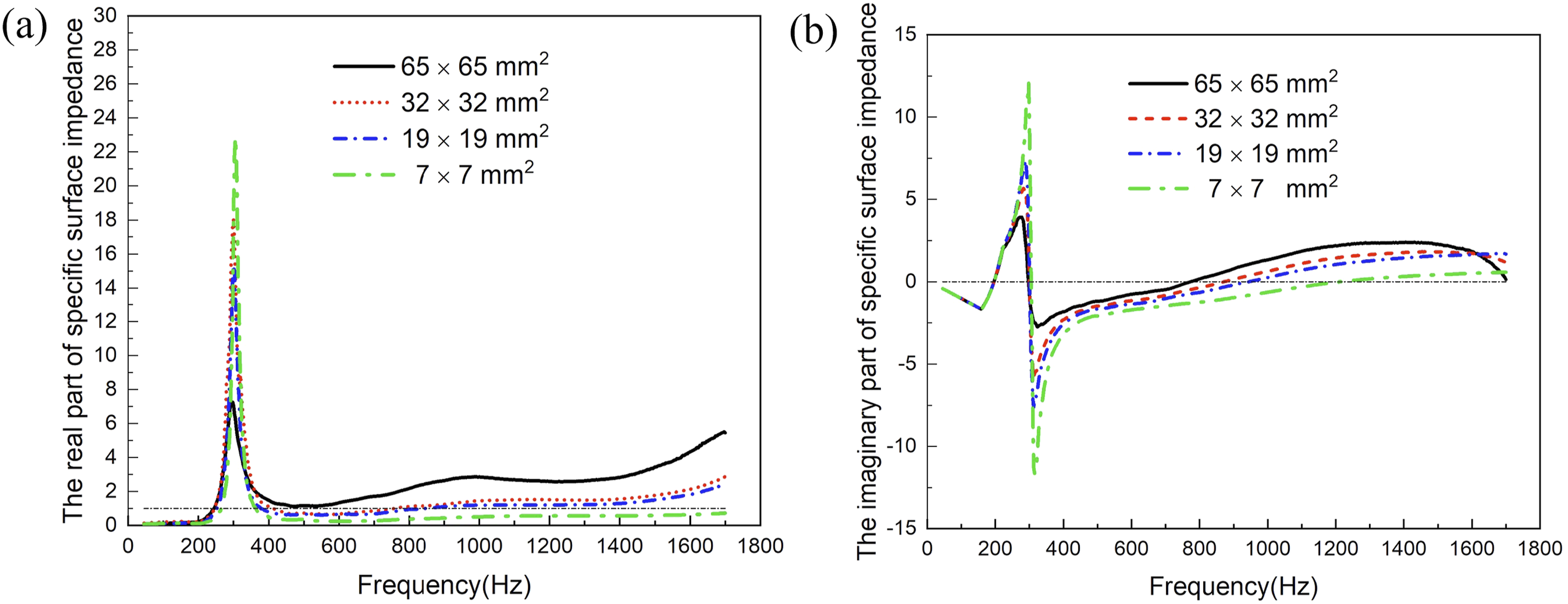
Figure 10(a)–(d) show FPP materials with different area of one PP unit, and sound absorption are shown in Figure 10(e). The area of FPP material is 65×65mm2, 32×32mm2, 19×19mm2, 7×7mm2, respectively.
From Figure 10(e), we can see that the frequency of sound absorption peak of FPP material with area of one PP unit 65×65mm2, 32×32mm2, 19×19mm2, 7×7mm2 is 728Hz, 883Hz, 928Hz and 1223Hz, respectively. It indicates that the frequency of sound absorption peak moves towards to the lower frequency and sound absorption at the low frequency was improved with increasing of size of one PP unit. It can be explained by the imaginary part curves of the specific acoustic impedance of FPP absorber shown in Figure 11(a) and (b). The reactance of FPP increases more quickly with the increasing of the size of PP unit which causes the reactance to reach to the zero line earlier, resulting in the lower sound absorption peak frequency.
3.2. Theoretical model of FPP absorber
The structure diagram and the equivalent circuit diagram of FPP sound-absorbing structure is shown in Figure 12(a) and (b). FPP absorber structure: (a) Structure diagram, (b) equivalent circuit diagram.


According to the acoustic theory of micro-perforated plate,23,24 the relative acoustic impedance 


The comparisons of calculated values by using the new model and measured values of sound absorption coefficient were shown in Figures 13–16. The pore diameter of fiber fabric in FPP1, FPP2, FPP3 and FPP4 materials all is 0.15 Comparisons of calculated and measurement sound absorption coefficients of FPP1 sound-absorbing structure. Comparisons of calculated and measurement sound absorption coefficients of FPP2 sound-absorbing structure. Comparisons of calculated and measurement sound absorption coefficients of FPP3 sound-absorbing structure. Comparisons of calculated and measurement sound absorption coefficients of FPP4 sound-absorbing structure. The computational values of 


The root mean square error (RMSE) of peak frequency, peak value and the average sound absorption coefficient (SAC) between calculated values and measured values for four FPP samples.

The proposed sound absorption model can accurately predicts the peak value and average SAC of FPP absorber. But the prediction error of the peak frequency was large for FPP with the more number of PP units.
4. Conclusion
Different from additional porous and PP laminated structure, a new flexible composite fabric sound-absorbing integrative structure with periodic PP units is proposed. The composite fabric material is made of flexible fabric weaving structure filled in the periodic PP units. The results show that FPP has the higher peak value and the wider bandwidth of sound absorption than PP and laminate structure. Meanwhile, the total area of PP units in FPP material decreased obviously, and the new FPP material solved the interface delamination problem in porous and PP laminated structure.
The frequency of sound absorption peak moves towards to the lower frequency with increasing of size of one PP unit because that the reactance of FPP absorber with large size PP unit increases more quickly which causes the reactance to reach to the zero line earlier. The developed theoretical model based on the equivalent circuit method can accurately predict the sound absorption peak value and average SAC of FPP material absorber.
The new flexible porous frame material and the new broadband sound absorption structure have advantages of low cost, flexibility, porosity, diverse structural designing, and good sound absorption. It can represent an alternative to PP or PP/porous laminated material.
Footnotes
Acknowledgements
The authors wish to thank Zhijun Chen for their warm-hearted help with equipments and samples.
Funding
The authors disclosed receipt of the following financial support for the research, authorship, and/or publication of this article: This research is supported by National Natural Science Foundation of China (12304522).
Declaration of conflicting interests
The authors declared no potential conflicts of interest with respect to the research, authorship, and/or publication of this article.