
Abstract
The impact of underwater explosions is destructive. Current research primarily focuses on engineering protective materials, with limited attention given to materials for human protection. A composite has been developed for the mitigation of injuries caused by explosive impacts, consisting of a carbon fiber laminate, an artificial cartilage foam (ACF), and a Kevlar fabric. A finite element model was then constructed, which incorporated the explosion source, the composite, and an equivalent human body (EHB). This model was utilized to evaluate the effects of front and backing plate thicknesses and core panel density on the impact resistance and protective performance of the composite, from both material and human body perspectives. The results revealed that the impact resistance initially increased and, thereafter, decreased with a larger front plate thickness, core panel density, and backing plate thickness. This was caused by an excessive thickness or density impeding overall compressive deformation. In terms of the protective performance, the composite showed an optimal protection for front plate and backing plate thicknesses of 1.2 mm and 1.26 mm, respectively. Also, the relationship between the core panel density and the protective performance was nonlinear since the variations in the density altered the degree of wave impedance mismatch between the layers, thereby affecting the overall protective effectiveness. The optimal protective performance was obtained for a core density of 300 kg/m3. These findings have provided a theoretical basis and technical support for the design and safety evaluation of underwater explosion protection composites for human protection.
Introduction
Commercial diving workers may be at risk for injuries from underwater explosions during their job duties. An explosion occurred during an underwater sludge treatment operation in Hainan Province, China, in 2020. 1 This operation was conducted by an environmental protection technology company, and resulted in three fatalities and two injured workers. The severe injury rate among individuals who are exposed to underwater explosions can reach as high as 70%, with following treatment difficulties and a high mortality rate.2,3 Therefore, the mitigation of injuries caused by underwater explosions has become an urgent issue in the field of personal protection. Currently, there are no personal protective materials that are capable of effectively mitigating blast injuries caused by underwater explosions. 4 The existing underwater protective materials have their origin in engineering fields, including roller-compacted concrete, 5 ceramic materials, 6 foam sandwich structural materials,7–9 and fiber-reinforced materials.10–12 These materials are primarily used for underwater dams, bridge piers, submarine pipelines, subsea tunnels, and navigation. 13 Their protective roles are to hinder the propagation of explosion shock waves, absorb the impact energy, etc. Moreover, high-performance materials have been produced by the development of novel materials,6,14 advancements in the manufacturing technology,10–12 and structural optimization at both micro and macro scales.7–9 However, these materials cannot be used for personal protection due to their excessive weight and thickness.
In the field of personal explosion protection, the existing protective clothing is not suitable for underwater blast protection for two main reasons. One is the difference in the protective mechanisms. The existing bomb suits are designed for air scenarios, 15 thereby intended to resist shock waves, fragments, and high temperatures with a primary focus on fragment protection. Unlike air explosions, the underwater explosions primarily impose damage through shock waves that propagate over large distances and at higher speeds. The damage and lethality range for the explosions in water can be up to three times larger than for the air explosions. 16 Another reason is that it has been discovered, by using experimental and numerical simulation methods, that garments made of an impact-resistant fabric (such as aramid fabric (Kevlar) or ultra-high molecular weight polyethylene (UHMWPE)) cannot provide protection and may even aggravate the human injuries under the conditions of an underwater explosion.17,18 Therefore, it is important to develop wearable novel materials that effectively provide protection against underwater explosions.
To verify whether the design goals for the materials have been achieved, their properties have been evaluated by comparing the values of various indicators (such as the absorbed energy,19,20 acceleration, 21 stress, and strain 22 ). These values can quantitatively characterize the energy absorption and dynamic mechanical response of the materials under an explosive loading.23–25 For example, large energy absorption, specific energy absorption, energy absorption efficiency, longer plateau stress segments, and smaller peak stresses do all indicate a superior impact resistance performance of the materials.17,18,26 Previous studies have focused on the dynamic response of the composites and the mitigation of shock wave loading. However, only a limited number of studies have evaluated the properties of the composites from the perspective of human body protection. The energy absorption capacity of the protective material is not directly comparable to its protective capacity for the human body. 27 This notion has been supported by Wang et al., 28 who found that the energy absorption of negative gradient cellular metallic materials was larger than that of positive gradient cellular metallic materials. However, the latter materials generated smaller peak impact stresses, which are more advantageous for human protection. Therefore, it has been stressed that bio-mechanical response parameters can objectively reflect the load levels that are experienced by the damaged tissue. Thus, the evaluation of the protective ability of the materials will be more reliable when using these parameters.29,30
In the present study, starting with the demand for underwater explosion protection of the human body, a novel protective material has been designed and developed. Both the shock wave resistance and wearing comfort have then been considered. The structural parameters of these composites were optimized using finite element simulations. Moreover, the dynamic responses of the composites and their protective effectiveness for the human body were separately analyzed and compared.
Novel design of composites for human protection
Design principles
Protective materials protect the human body by reflecting and absorbing the explosion shock wave, thereby weakening the shock wave before it reaches the human body. The multi-layer structural design of composites provides an effective solution. Previous studies have shown that such designs can reflect and transmit shock waves multiple times, thereby increasing the energy dissipation from the explosion.31–33 Moreover, personal protective materials that are used to mitigate the effects of underwater blast wave impacts must meet at least three key requirements.
One requirement is the high strength and modulus of the material, which signifies its superior ability to resist deformation and damage caused by external impacts.34,35 This is because the interaction between the shock waves and the target material induces both compressive and tensile stresses, which can lead to phenomena such as plastic deformation and fracturing. In addition, the materials should be designed to minimize irregular deformations, which may cause secondary injuries to the human body. Another important characteristic is the high energy absorption capacity, which facilitates the absorption and dispersion of the shock wave energy. This can reduce the amount of energy transmitted to the human body through the material, and alleviate stress concentration. Specifically, materials with a higher tensile strength and larger elongation typically exhibit a higher potential for energy absorption. The final requirement is the comfort of wearing, which involves two aspects. On one hand, the material should be as lightweight and thin as possible to minimize adverse effects on the ergonomics during use. On the other hand, the side of the material that is in contact with the body should have sufficient softness and elasticity to reduce any discomfort caused by friction and irritation.
The characteristics of high strength and modulus, excellent energy absorption capacity, and wearing comfort are relatively contradictory, making coexistence difficult in a single material. Materials with a high strength and modulus tend to be hard and resistant to deformation under impact, whereas an effective energy absorption typically requires sufficient deformability. Moreover, these properties may compromise the comfort of wearing, which requires opposite characteristics (such as being lightweight, thin, and soft). Therefore, multi-layer composites have been designed to balance these properties, with different layers serving distinct functions in the overall protection.
Composition of novel composites
According to the design principles presented above, three-layer composites have been developed in the present study. These layers are denoted as front plate, core panel, and backing plate.
Front plate (for shock wave disruption)
Based on an extensive literature review and market research, it has here been found that hard materials (such as silicon carbide (SiC), alumina (Al2O3), and carbon fiber laminate) are widely used for explosion control, which is due to their high hardness, wave impedance, strength, and modulus. In the present study, a carbon fiber laminate was selected for shock wave reflection. This selection was based on a comprehensive consideration of the superior mechanical performance, lightweight characteristics, advanced industrial maturity, and cost-effectiveness of this specific material.
Core panel (for shock energy absorption)
The shock wave energy can be absorbed by porous materials (such as polystyrene (PS), polyurethane (PU) foams, aluminum foams, and artificial cartilage foam (ACF)). These materials convert the shock energy into heat, or mechanical work, by a pore collapse mechanism. This mechanism contributes to an effective mitigation of the explosion impact. However, metallic materials are excluded due to potential issues with durability and lifespan in underwater environments. According to the test results presented in a previous study by the present authors, which was based on the Split Hopkinson Pressure Bar (SHPB), the ACF exhibits a high-energy absorption rate and remains free from visible damage. This result is in contrast to materials such as PS and PU, which are prone to damage under high-strain rate conditions. Moreover, the ACF has been widely used for impact protection and in personal protective equipment, which is due to its light weight and excellent energy absorption characteristics. Therefore, the ACF has been selected here for shock energy absorption.
Backing plate (for shock wave spreading and comfort wearing)
Although the shock wave energy is initially disrupted in the first and second stages by the carbon fiber laminate and ACF, it is further attenuated through dispersion by using high strength fabrics. This layer of fabric is also suitable for use as the innermost material (i.e., for the contact with the human body), which is due to its softness. Therefore, the Kevlar-29 plain-woven fabric was selected for this purpose. This decision was supported by findings from the literature review and market research, which identified the Kevlar fabric with its widespread applications in protective equipment and, therefore, highlighted its strong potential for the industrial-scale production of newly developed composites.
As can be seen in Figure 1, these composite materials have been integrated in a layered form. The connections between the layers were simplified to adhesive joints. This type of designed composite is meant to be used on the exterior part of the protective clothing, with the purpose to absorb a portion of the energy from the explosion and to reduce the force that is transmitted to the human body. Schematic showing the structure and function of the designed composite for human protection against underwater explosions.
Determination of changeable parameters during optimization
It is important to investigate the structural parameters of each layer in the three-layer composite to ensure that the composite exhibits an excellent protection performance under underwater explosion conditions. For this purpose, a theoretical analysis has been performed to determine the optimal structural parameters for the novel composite.
During an underwater explosion, the shock wave acts on the surface of the material structure. It is known that the incident and reflected waves rapidly combine at the surface,36–38 which results in an impact pressure that corresponds to the motion and compressive deformation of the material. This impact pressure can be calculated using equation (1).

In this context, after the shock wave has acted on the material, the surface pressure will be affected by the resulting diminishing force from the spatial displacement of the plate. The present study has focused on the impact resistance mechanism in the material under an explosive load. Therefore, it has been assumed that the material will not undergo any spatial displacement, but its capacity to withstand a maximum impact load has instead been emphasized. When the explosion source is trinitrotoluene (TNT) in a spherical form, the underwater shock wave pressure can be calculated using Cole’s empirical formula (equation (2)).

When considering the structural characteristics of a composite consisting of foam, it was assumed that the primary origin of the deformation energy absorption during impact was the core foam. However, the front and backing plates remained undeformed. In this scenario, the dynamic response of the three-layer composite under the impact load of an underwater explosion could be simplified into three stages. In the first stage, only the front plate in the composite acquired an initial velocity under the influence of a fluid-structure coupling. The core panel and backing plate remained stationary. In the second stage, the impact load was gradually transferred to the core panel and the backing plate, after which the front plate reached its initial velocity. Subsequently, the core panel underwent a compressive deformation, which was accompanied by energy absorption. Once the core panel reached the same velocity as the front plate, the compression of the core panel was completed. In the third stage, the material as a whole continued to move at the same speed under the inertial effect until the velocity reached 0 m/s. Figure 2 presents a simplified schematic diagram, which illustrates the dynamic response of the composite under explosive impact. Simplified schematic diagram showing the dynamic response of the composite.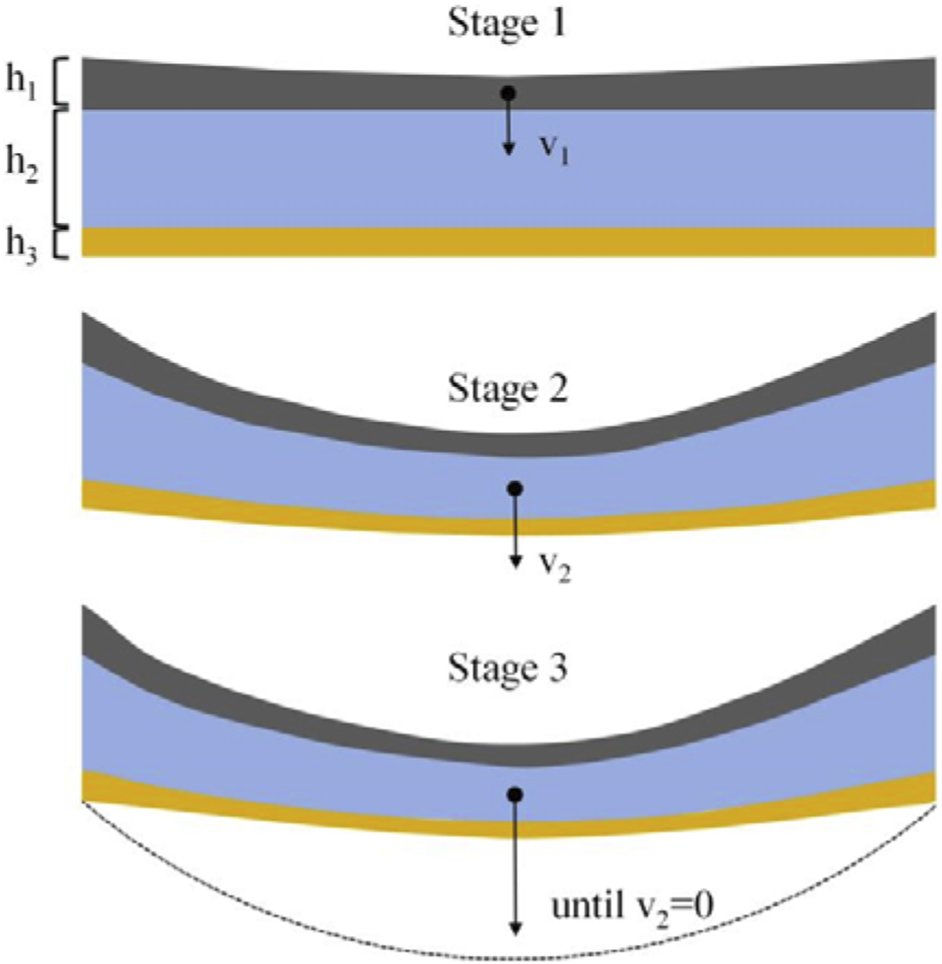
Based on the dynamic response analysis of the composite and by integrating the momentum theorem, the initial velocity, ν
1
, of the front plate could be calculated using equation (3).

According to the kinetic energy theorem, the initial energy, E
1
, of whole composite could be calculated using equation (4).

In the second stage, the overall velocity of the composite remained the same. According to the conservation of momentum, the velocity of the composite, ν
2
, could be calculated using equation (5).

Furthermore, the total kinetic energy of the material after the completion of the compression, E
2
, could be calculated using equation (6).

During the compression, the composite absorbed some of the energy from the explosive impact load. The absorbed energy, E
absorb
, could be calculated using the initial kinetic energy, E
1
, and the kinetic energy after the completion of the compression, E
2
(equation (7)).

Based on the equations presented above, it could be concluded that an increase in the thickness and density of the front plate decreased the initial energy and also reduced the total kinetic energy of the material. This created a challenge in determining whether an adjustment of these parameters will enhance the overall energy absorption and impact resistance of the material. On the contrary, an increase in the thickness and density of the core panel and backing plate increased the total energy absorption of the composite.
According to the stress wave theory, 39 stress waves going from low-impedance materials to high-impedance materials, or from high-impedance to low-impedance materials, can result in either stress amplification or attenuation. Based on the known propagation characteristics of the stress wave, the thicknesses of the front and backing plates of the composite, rather than the density, have been in focus. These thicknesses are related to the wave impedance. Moreover, for the core panel material, which dominated the total thickness of the composite, an excessive thickness could negatively impact the ergonomic functionality. Although an increased core panel thickness would improve the protection performance, it could not be increased indefinitely due to practical limitations. In contrast, the adjustment of the density would offer a larger flexibility.
Another focus in the present study has been the effects of the front plate thickness, core panel material density, and backing plate thickness on the impact resistance of the composite and its protective performance for the human body. Numerical simulations have been used for the analysis of these effects.
Finite element simulations
Given the high risk and cost of underwater explosion experiments, numerical simulation provides an effective means to reduce experimental workload and expenses during the early stages of material development. Moreover, it enables the capture of critical characteristics that are difficult to obtain through physical testing, thereby offering more comprehensive data for in-depth exploration of mechanisms.
Finite element models
The impact load condition presented in Ref. 40 for the underwater explosion has been used in the present study. It was then reported that the lethal boundary is 9 m under 1 kg of TNT in underwater explosion experiments with beagles. The protective composite, which has been developed in the present study, was intended to reduce the severity of human injuries for underwater blast conditions. Therefore, the finite element model was configured with a 1 kg TNT charge and a standoff distance of 10 m. Previous studies 41 have shown that underwater explosions primarily damage gas-filled organs within the thoracic cavity, making these areas particularly important to protect. Therefore, the protective material should cover key organs (such as the lungs and heart), and their dimensions should be set to 200 mm * 200 mm.
When considering the significant difference in scale between the explosion distance and the composite thickness, as well as the computational costs for the numerical simulations, the original large charge, long-distance explosion conditions have been consistently transformed into a small-charge, short-distance condition while keeping the impact load on the protective material constant. Therefore, the TNT charge was set to 0.129 g, with a detonation distance of 500 mm, in the numerical model that was developed in the present study. To further improve the computational efficiency, a quarter of the simulation model for an underwater explosion was constructed (Figure 3). The size of the water domain was 120 mm * 120 mm * 600 mm and it was modeled using 10, 180, 000 hexahedral elements, each with an element size of 2 mm, which was determined by convergence analysis. Also, the geometric model of the composite measures 100 mm * 100 mm * thickness, and its composition is consistent with the experimentally designed sample. Approximately 100,000 hexahedral elements were used to model the composite, with an average element size of 1 mm. Moreover, a 5 cm thick clay, which has been reported in Refs. 42,43, was used as a substitute for the human body. The dimension of the EHB domain was 100 mm * 100 mm * 50 mm, and it was modeled using 1 million hexahedral elements. Geometric model of the composite, EHB, and water.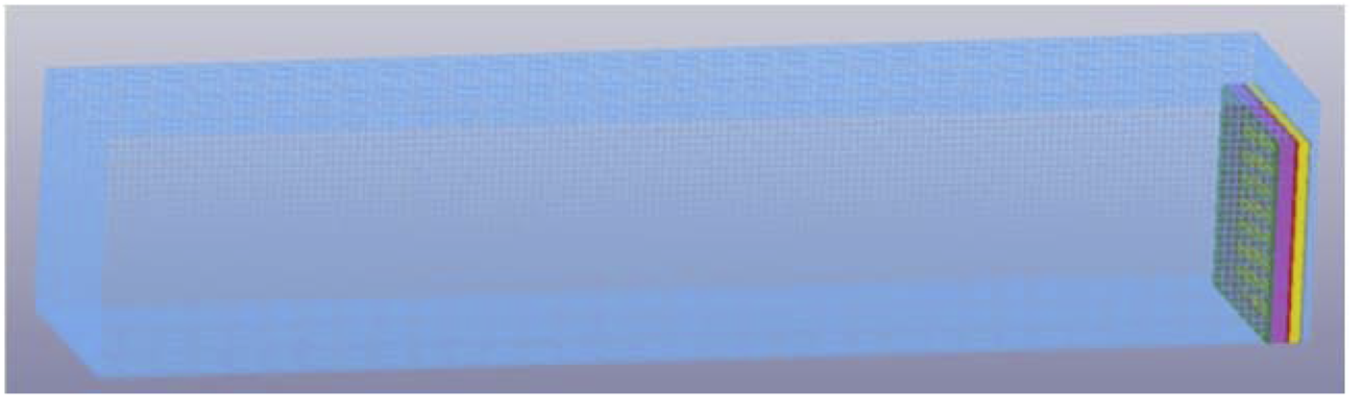
Constituent materials and basic structural parameters for the newly designed composites.

The simulation time was set to 1.5 ms, which ensured that the shock wave could complete its energy release in an open environment, and also allowed sufficient interactions between the underwater shock wave, water, and composite. During the simulation, data from the fluid (i.e., water) domain and composite elements were written into a binary history file. 46 These data were processed to determine the indicators for the analyses of the dynamic response of the composite and EHB over the entire simulation (including peak overpressure, energy, acceleration, displacement, and stress). The computational time for each case was approximately 50 h (NCPU = 8) on a workstation with 24 XEON cores.
Properties of the models
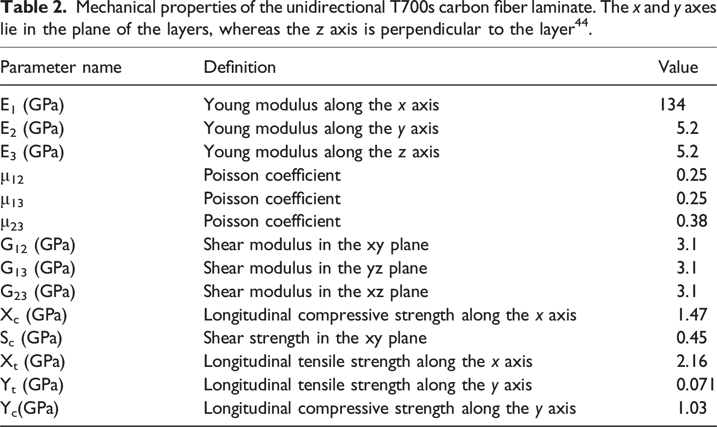
Carbon fiber laminate
A T700s carbon fiber has been used in the present study, with a layering direction of [0°–90°].
44
Also, the material model that was used for the replication of the orthotropic mechanical properties of the unidirectional carbon fiber laminate was the *MAT_ENHANCED_COMPOSITE_DAMAGE. The failure criteria (Chang-Chang) for the tensile and compressive modes were then defined as shown in equations (8)–(10).
47


Artificial cartilage foam (ACF)
To obtain the stress-strain properties of the ACF samples at different strain rates, high strain rate tests were conducted using Split Hopkinson Pressure Bar (SHPB). The conventional SHPB steel is suitable to use when testing metallic materials, but it cannot precisely capture the dynamic responses of soft materials (like foams). To overcome this limitation, a Perspex bar was used instead of a metal bar in the tests. The mechanical impedance of the Perspex bars was much closer to that of the ACF specimen. Therefore, the transmitted wave was sufficiently large to be accurately measured. Figure 4 shows the stress-strain curves of the ACF under different impact speeds of the bullet bar. Similar to other foams that have been reported in the literature, the ACF showed a strain rate sensitivity. The stress-strain curves of the ACF showed three distinct regions: (1) A linear elasticity at low strains, which is dominated by cell wall bending; (2) A long plateau representing the main energy absorbing stage; (3) A densification region during which the stress increases rapidly.
48
Strain-stress curves of the ACF under different bullet impact velocities.
To describe the behavior of the ACF under explosion (i.e., transient impact), the selected fundamental models took both failure and strain rate effects into account. The *MAT_PIECEWISE_LINEAR_PLASTICITY model is an elastic-plastic material model that describes the strain rate effects. It determines the stress-strain response and yield stress for a specific strain rate by interpolating between curves that correspond to different strain rates. In the present study, experimental results, which were obtained at the strain rates of 480 s−1, 537 s−1, 556 s−1, and 585 s−1, were imported into the finite element software as input data. In addition, the required parameters for the model included the density and elasticity modulus, which could be calculated from the slope of the initial linear portion of the stress-strain curve.
Kevlar-29 plain-woven fabric
The routine that was used to reproduce the orthotropic mechanical properties of the Kevlar-29 plain-woven fabric was the *MAT_ENHANCED_COMPOSITE_DAMAGE. This model included failure criteria for both the fibers and the matrix. Fiber failure took place under tensile stress (equation (11)) or compression (equation (12)). The failure criterion (Tsai-Wu) for the matrix under tensile and compressive loadings can be calculated using equation (13).


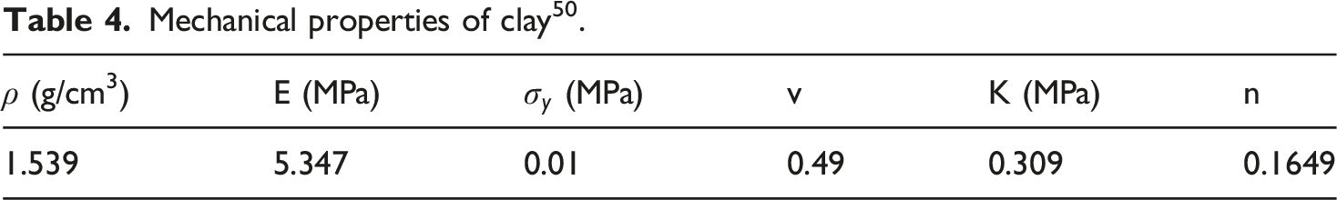
Equivalent human body (EHB)
The power-law plasticity model can describe the strain-rate hardening behavior of a material, which aligns with the characteristics of clay.
49
The stress-strain relationship, σy, of clay can be calculated using equation (14).
Load and boundary conditions
Simulations of an underwater explosion shock wave

Parameter values for the explosive TNT material.


Values of the equation of state (Grüneisen) for water.

Boundary conditions and contact modeling
The impact acts directly on the upper plate of the composite. The interactions between the shock wave and the composite is a typical fluid-structure interaction problem. In the present study, the Arbitrary Lagrange Eulerian (ALE) technique has been used to simulate the propagation of shock waves52,53 and their interactions with the composite.
Following the guidelines in Refs. 54–56, non-reflecting boundary conditions were used for the four free surfaces of the water domain, excluding the symmetry-constrained surface. These boundary conditions allowed the shock waves to flow out directly, thereby simulating the explosion environment in the free field and avoiding secondary reflections of the shock wave that could otherwise affect the composite. This made the simulation results more consistent with the actual situation. Moreover, it was assumed that the EHB would not undergo spatial displacement during impact. Furthermore, fixed boundary conditions were imposed on the bottom edge of the EHB model, thereby constraining the translational and rotational degrees of freedom along the x, y, and z directions.
The selection of appropriate contact settings is crucial in finite element analysis. An incorrect contact may result in solution non-convergence, which leads to a premature termination of the calculations. 57 There were two different contacts in the present study. Firstly, the *CONTACT_SURFACE_TO SURFACE_TIEADBREAK was used to model the contact between each Kevlar layer. This approach required normal and tangential threshold stresses, which allowed for a separation between the surfaces once the threshold was reached. The normal and tangential threshold stresses for the Kevlar with a polymeric matrix were 34.5 MPa and 9 MPa, 58 respectively. Secondly, the *CONTACT_ AUTOMATIC _SURFACE_TO_ SURFACE module in LS-DYNA, with the option of a soft constraint formulation, was used to simulate the contact behavior between the carbon fiber laminate, ACF, Kevlar, and EHB. This contact model was designed for simulating the processing of the laminated composites. Surfaces in contact can support a shear up to the limit defined by the model, and can be in compression, or tension, up to the tensile limit. This modeling approach is supported by the methods reported in the literature.59,60
Validation of models
Shock wave of underwater explosion simulation verification
Two feature points in the water domain were selected to verify the peak pressure at different distances (350 mm and 500 mm) from detonation point. The simulation results for a peak overpressure were 5.24 MPa and 4.53 MPa, respectively. These values were compared with the peak overpressures (5.88 MPa and 3.93 MPa), which were calculated by using the equation (18) (by Cole and Zamyshlyayev).61,62 The obtained peak overpressures from the simulations were slightly different from the calculated ones, with a maximum error of 15.27%. Since this error was less than 20%, it was found reliable to use the simulation results as input loads for the composite.
Material model of each layer
Validation of the carbon fiber laminate
The material model for the carbon fiber laminate was validated using data from the referenced literature. 44 Based on important experiments described in the literature, a numerical model was developed to simulate the bullet impact on the laminate. The bullet was a cylindrical projectile, with a diameter of 16 mm and a length of 19 mm. It was made of a 45 steel, which underwent almost no deformation during the experiment. Thus, its deformation under stress could be neglected. Also, the dimension of the target plate was 130 mm * 130 mm * 4 mm and consisted of 20 layers of a thin T700S unidirectional carbon fiber plate. Each of these plates had a thickness of 0.2 mm. A cohesive contact was defined between these layers. In addition, the contact between the bullet and the carbon fiber laminate was defined using the *ERODING_SURFACE_TO_SURFACE contact algorithm, with a friction coefficient of 0.3 44 for both static and dynamic situations.
The experiment, with a bullet impact speed of 175 m/s, was numerically simulated, and the remaining bullet velocity was calculated. The result from this simulation was compared with the experimental results. The simulation results did closely match the experimental results, with the values of 144 m/s and 148 m/s, respectively. There was an error within 2.7%. Thus, it was evident that the material model for the carbon fiber laminate was relatively accurate.
Validation of the ACF
The material model of the ACF was validated using experimental data from the SHPB test. The geometric model replicated the real device, where the incident bar and transmission bar were cylinders with a diameter of 30 mm and lengths of 180 mm and 150 mm, respectively. The material of the SHPB was Perspex, with a density of 1.16 g/cm3 and a Young’s modulus of 3160 MPa. Also, the contact between the ACF and the Perspex bars was defined as a surface-to-surface contact, with both the static and dynamic coefficients of friction set to zero.
Two different incident waves (with bullet bar velocities of 23 m/s and 27 m/s) were selected as initial boundary conditions, and the transmitted waves from both the simulation model and the experiment were compared. As can be seen in Figure 5(a) and (b), the difference between experimental and numerical results was less than 10%. This proved that the constructed ACF model was effective for strain-rate dependent materials. Comparison between simulations and experimental results. Transmitted waves for a bullet bar velocity of (a) 23 m/s (error = 6.74%) and (b) 27 m/s (error = 3.51%).
Validation of the Kevlar-29 plain-woven fabric
To verify the validity of the model of the Kevlar-29 plain-woven fabric, the experimental data from Ref. 45 were simulated and reproduced. In the experiment, the bullet was a cylinder with a diameter of 10 mm and a length of 20 mm. The bullet material was tungsten, with a density of 19.35 g/cm3. It underwent almost no deformation during the impact on the plate target. Also, the plate was made of individual layers, each approximately 0.42 mm thick. The 5 mm thick plate consisted of 12 layers in total, and the length of the square plate was 150 mm. Furthermore, the contact between the bullet and the Kevlar-29 plate target was defined as *ERODING_SURFACE_TO_SURFACE, with a friction coefficient of 0.18 for both static and dynamic situations. 63 In addition, the boundary of the target plate was set fixed.
The experiment with an incident velocity of 218 m/s was simulated. The remaining velocity from the simulations was 204 m/s, which was slightly higher than the experimentally measured residual velocity of 197 m/s. The main explanation for this observation was an inclination angle during the impact of the bullet in the experiment, and it affected the erosion ability of the bullet on the plate target. There was also a difference between the numerical simulations and the experimental results. However, this error was small, only 3.55%, which demonstrated the effectiveness of the Kevlar-29 material model.
Overall, the shock wave transmission process of underwater explosion and the material models have been satisfactorily simulated. Thus, it has been found that the developed numerical model can be used for analyses of subsequent dynamic response characteristics and protection mechanisms.
Evaluation indicators
The dynamic response of materials under explosive loads is closely related to their impact resistance properties. Previous studies have evaluated the impact resistance of materials by comparing indices such as stress, 22 pressure attenuation,17,18 acceleration, 21 deformation damage64,65 and energy absorption.19,20 A higher energy absorption rate, higher pressure attenuation rate, lower acceleration, stress, and deformation damage did all indicate a superior impact resistance of a material. According to the design principles of the composite in the present study, the front plate disrupted the shock wave, the core panel absorbed the explosion energy, and the backing plate further dispersed the shock wave.
Bio-mechanical response parameters could objectively reflect the load level that was experienced by the damaged tissue, making these parameters more reliable in the evaluation of the protective performance of the material. Indicators (such as the peak overpressure, von Mises stress, and peak acceleration of the EHB) were found to be critical for the assessment of the load borne by the damaged tissue and for objectively estimating the extent of injuries to the human body. 66 The smaller the injury to the protected human body, the superior the protective performance of the material. The following analysis has focused on these indicators. It has been important to emphasize that, rather than directly studying the degree of human injuries based on bio-mechanical responses, key parameters for the resistance of shock waves and the reduction of human body damage have, in the present study, been quantified and compared for various structural composites.
Results and discussion
Effect of front plate thickness
Impact resistance properties
It is well known that after an underwater explosion, the detonation wave propagates outward and immediately transforms into a strong compression wave and a diffusive motion in the water surrounding the TNT charge. A strong fluid-solid coupling effect occurs when the shock wave reaches a material, which results in both transmission and reflection at the surface of the structure. This interaction generates a primary shock wave and a secondary shock wave. The pressure and internal energy at the wavefront of the secondary shock wave correspond to those behind the primary shock wave and cannot therefore be directly ignored.
67
From the perspective of the mechanical behavior, an interaction force arises between the impact load and the protective material, which leads to pressure fluctuations on the surface of the material. Figure 6 shows the pressure-time curves of composite surfaces with varying front layer thicknesses. Under an impact loading, the surface pressure of the composite showed time-dependent fluctuations. As the thickness of the carbon fiber laminate on the front plate surface increased, the corresponding pressure load also increased. Pressure-time curves for composite surfaces with varying front layer thicknesses.
Figure 7 shows the stress-time curves for the surfaces of the front and backing plates of the composite. It is evident that the stress in the front plate surface was significantly higher than that in the backing plate. The reason for this observation might be that the front plate absorbed part of the impact energy through deformations and other mechanisms, which resulted in a smaller load and, thus, a smaller stress variation when the impact energy reached the backing plate. Effective stresses in composites with varying front layer thicknesses. (a) Front plate surface and (b) backing plate surface.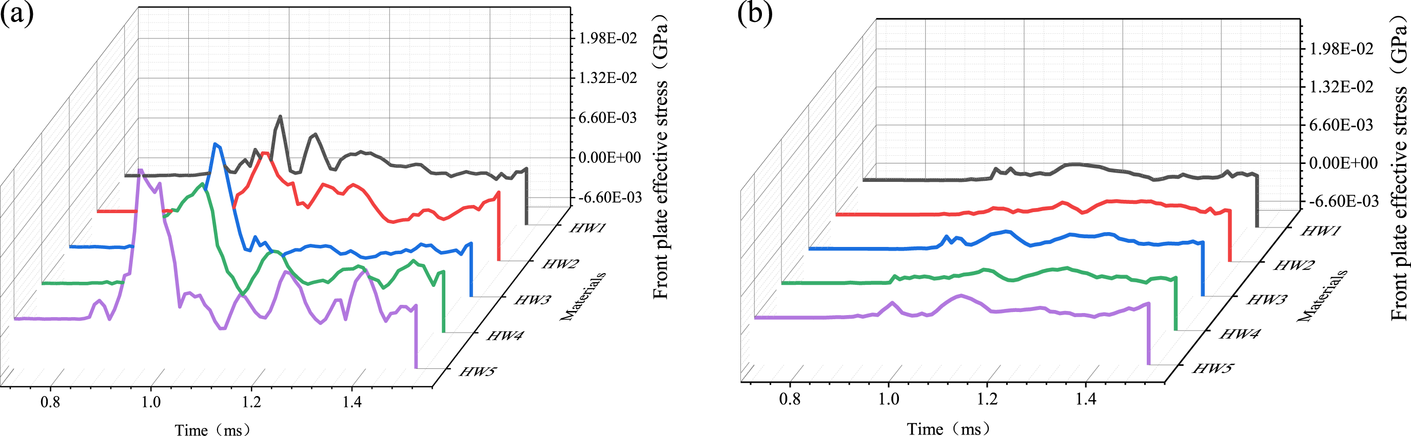
Figure 8 shows stress cloud maps of each layer of a composite with front plate thicknesses of 0.4 mm and 2 mm. Due to the differences in these thicknesses, the time required for the load to propagate to each layer varied, which resulted in different stress distribution patterns across the layers. The material layers that were closer to the blast-facing surface experienced higher stress levels than those further away. Moreover, each layer exhibited a non-uniform in-plane stress distribution. It was also observed that the stresses in the boundary regions were relatively high, which could be attributed to the fixed boundary conditions along the edges during the numerical simulations. Since the boundary regions have not been in focus in the present investigation, the stress conditions at the boundaries could be disregarded when evaluating the stress characteristics of the material. Furthermore, at 0.12 ms, the stress in the upper surface of the composite, with a 2 mm front plate, was significantly higher than that observed with a 0.4 mm front plate. In contrast, the stress in the backing surface of the 2 mm thick front plate was lower than that of the 0.4 mm thick one. The reason was that the thicker front plate absorbed more impact energy, thereby reducing the energy that was transmitted to the lower layers. This resulted in a lower stress magnitude. Stress cloud maps of each layer of composites with front plate thicknesses of (a) 0.4 mm and (b) 2 mm.
Figure 9 illustrates the energy transformation within the composite for a front plate thickness of 0.4 mm and under the impact load of an explosion. It could be observed that the energy from the resulting shock wave became gradually converted into internal energy and kinetic energy within the composite. Upon reaching the material, the shock energy was initially transformed into structural kinetic energy. Subsequently, due to mechanisms such as material deformation, viscous dissipation, and frictional dissipation, the shock energy became rapidly transformed into internal energy.
68
At 1 ms, the total energy that was imparted by the shock wave on the composite reached its maximum value of 2.02E-2 kN-mm. At this point, the internal energy that was absorbed by the structure was 1.09E-3 kN-mm. Thereafter, the shock energy ceases to increase, and the kinetic energy of the material gradually dissipates into internal energy by rebound oscillations. Energy configuration of the composite for a front plate thickness of 0.4 mm.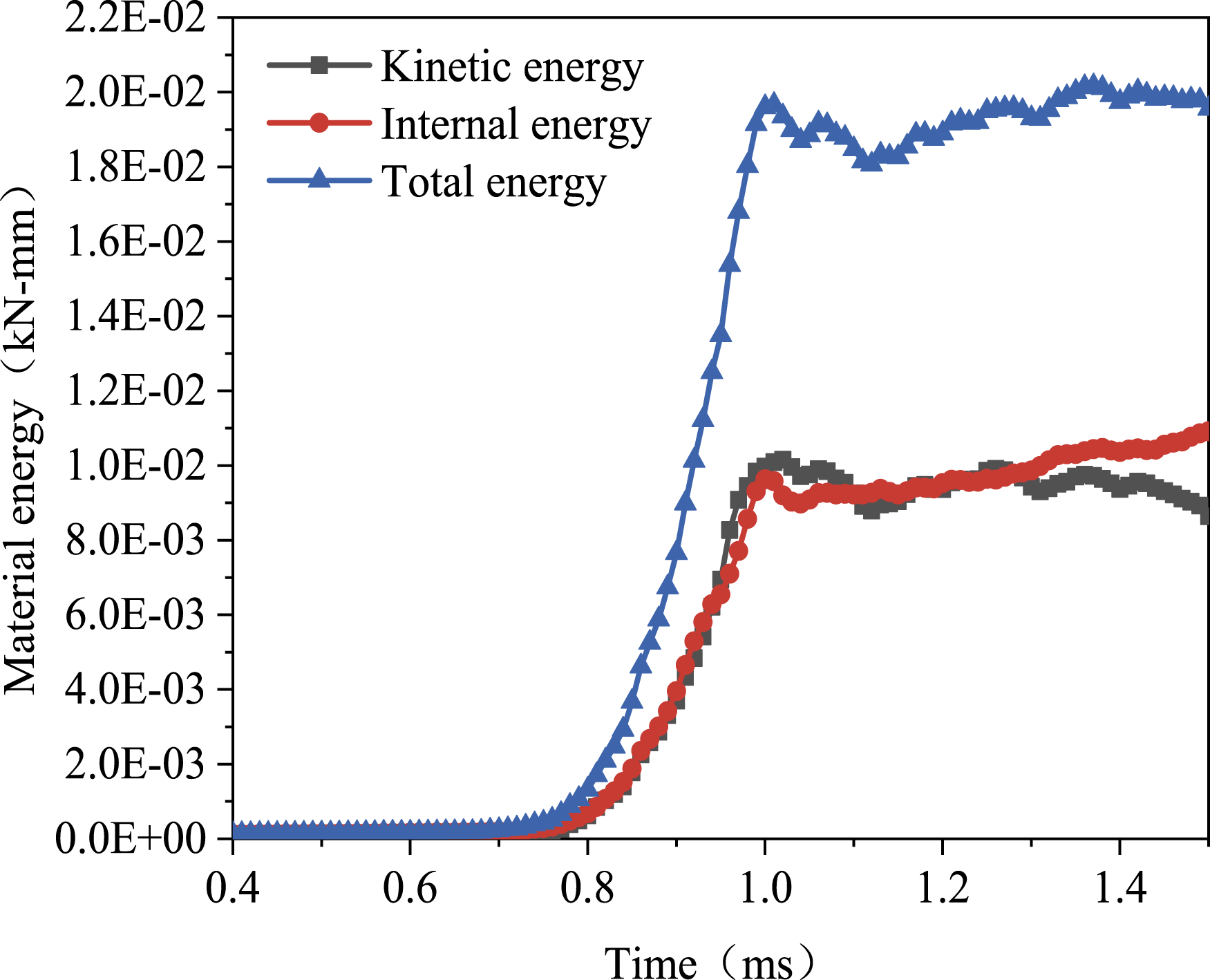
Figure 10 shows the energy relationship of composites with varying outer layer thicknesses. The total energies (kinetic energy + internal energy) of these composites were 1.96 kN-mm, 2.48 kN-mm, 2.02 kN-mm, 2.63 kN-mm, and 2.61 kN-mm. As the thickness of the front plate gradually increased, the total energies of the composites increased by 26.53%, 3.06%, 34.18%, and 33.16%, respectively. Furthermore, when the front plate thickness of the carbon fiber laminate was 0.8 mm, the energy absorption rate reached its maximum of 59.27%. In contrast, when the front plate thickness was 1.2 mm, the energy absorption rate reached its minimum of 53.96%. It was evident that the energy absorption rate of the composite did not exhibit a linear correlation with the thickness of the front plate. This phenomenon was supported by Refs. 69,70, which indicated that for the multilayer composite structure, which has been designed in the present study, the energy absorption performance was primarily influenced by the thickness ratio between the front plate and the core panel, and that there was an optimal ratio. As the thickness of the front plate increased, the propagation and reflection paths of the stress waves within the material became longer, which led to more complex internal stress states.
71
In turn, this resulted in a nonlinear variation in the energy absorption capacity. Energy configurations of composites with varying front plate thicknesses.
Protective performance
Figure 11 shows the peak overpressure of the EHB, also referred to as the transmitted pressure. This overpressure represented the pressure that reached the human body after passing through the protective material. Thus, it was desirable to minimize the transmitted pressure for the protective composite. When the front plate thickness was less than 1.6 mm, an increase in this thickness reduced the overall transmitted pressure of the composite (Figure 11). This observation aligned well with the findings of Wang et al.
72
They found that a thicker front plate resulted in lower transmitted peak pressure for a composite made of PU-Kevlar-EPP. When the thickness of the carbon fiber laminate was increased by 0.4 mm, the transmitted peak pressure of the material decreased by 6.86%, 6.60%, and 21.64%, respectively. However, when the thickness reached 2 mm, the transmitted pressure increased to 3.92E-4 GPa (3.43%). This indicated that the front layer thickness of the composite was not linearly correlated with its protective ability. For the composite that has been designed in the present study, the minimum pressure on the human body occurred when the thickness of the carbon fiber laminate was 1.6 mm. Peak overpressure of the EHB under the protection with a composite of varying front plate thicknesses.
Figure 12 shows the stress-time curves for the EHB that is protected by composites with different outer layer thicknesses. It is known that when the shock wave propagates from the low-impedance water material to the high-impedance interface of the protected human body, it can reflect off the surface of the human body. This reflection causes a jagged increasing trend in the stress waveform.73,74 The stress waves are the primary cause of blast-induced injuries to human tissues, as confirmed by numerous experimental studies. Under protective conditions, the higher the experienced von Mises stress by the human body, the larger the risks for injuries. Conversely, a lower von Mises stress indicates a better protective performance of the composite. As can be seen in Figure 12, as the front plate thickness increased, the peak von Mises stress for the EHB decreased by 43.44%, 49.77%, 42.99%, and 33.94%, respectively. This indicated that an increase in the thickness of the front plate gradually enhanced the overall protective performance of the composite. In addition, it should be noted that the impact of the increasing front plate thickness on the overall protective capability of the composite gradually diminished. Von Mises stress curves for the EHB under the protection with a composite of varying front plate thicknesses.
Figure 13 shows the acceleration-time curves for the EHB under the protection with five different materials. For explosion shock conditions, the propagation of the stress wave caused the human body to experience both compressive and tensile forces sequentially, which gradually weakened as the shock load propagated and dissipated. These forces induced accelerations in two directions within the human body, which caused the acceleration-time curve to gradually level off. It is important to note that the acceleration in the direction of the shock wave was defined as negative, while the acceleration due to tensile forces in the opposite direction was defined as positive. Figure 14 shows the peaks of positive and negative accelerations for the EHB under the protection with five different materials. As the thickness of the front plate increased, both the positive and negative peak accelerations for the protected EHB gradually decreased, which indicated that the risks for injuries to the human body diminished. Acceleration-time curves for the EHB under the protection with composites of varying front plate thicknesses. Peak accelerations for the EHB under the protection with composites of varying front plate thicknesses.

Based on the analysis presented above, it could be concluded that the impact resistance of the composite was not equivalent to its protective performance. For example, for the same underwater explosion conditions, the energy absorption rate of composite HW1 was higher than that of HW3. However, from the perspective of the protected human body, the risks for injuries were larger when using composite HW1 than when using HW3. Although an increase in the front plate thickness could improve its protective performance for the human body, to rely solely on this approach for practical applications might not meet protection requirements. Instead, it could also lead to higher costs and compromised ergonomic performances.
Effect of core panel density
Impact resistance properties
For identical explosion conditions, the attenuation pressure is one of the most direct indicators for the evaluation of the impact resistance of composites.17,18 A 1 kg TNT spherical charge at a distance of 10 m has been used in the present study. The peak shock wave pressure was calculated using the Cole empirical equation, which yielded a value of 3.88E-3 GPa. The peak pressure on the backing plate of composites with different core densities was subsequently obtained through numerical simulations. The calculated pressure attenuation rate (pressure attenuation rate = (3.88E-3 - peak pressure on the backing plate)/3.88E-3 GPa) for the composite is shown in Figure 15. It could be observed that as the density of the core panel ACF increased from 200 kg/m3 to 500 kg/m3. Also, the overall pressure attenuation rate of the composite initially increased and then decreased, with the respective changes of 0.86%, 9.26%, 0.72%, and −12.57%. When the core panel density reached 300 kg/m3, the overall pressure attenuation rate of the composite actually decreased. This finding was consistent with that of Qi Chang et al.,
75
who found that when the core panel material became sufficiently dense, it impeded the compression, thereby reducing the pressure attenuation rate.
76
Pressure attenuation for composites with varying core panel densities.
Figure 16 compares the energy absorption of each layer and the total energy absorption of composites with five different core panel densities. The composite exhibited the highest total energy absorption (1.15E-2 kN-mm) for a core panel density of 500 kg/m3, with the core panel contributing the most. On the other hand, the composite showed the lowest total energy absorption (1.04E-2 kN-mm) for a core panel density of 300 kg/m3. Energy absorption of each layer and deformation of the backing plate in composites with varying core panel densities.
According to previous studies, the deformation of the composite exerted a compressive force on the human body during the impact process, which resulted in bodily deformation. This deformation was associated with an injury, which potentially led to outcomes ranging from minor soft tissue damage to irreversible trauma, and even to mortality. 77 The deformation data of the backing plates for composites with five different core panel densities are presented in Figure 16. Despite the observable deformation differences among these materials, the magnitudes of these differences remained within the millimeter range (approximately 0.1 mm) and could, thus, be considered as practically negligible.
Moreover, it could be observed that there was no direct correlation between energy absorption and the back plate deformation. For example, in the case of composites DM2 and DM4, the deformation of DM4 was smaller although it exhibited a higher energy absorption. This observation was consistent with the findings by Zhang et al., 78 who reported that the total energy absorption and core panel energy absorption for honeycomb sandwich plates showed no direct correlation with backing plate deformation. However, it was generally believed that a smaller deformation of the backing plate indicated a better impact resistance. 79 Therefore, the energy absorption of a composite cannot directly reflect its resistance to impact and should not be solely relied upon as an indicator of its impact resistance performance.
Protective performance
Figure 17 shows the peak overpressures and peak von Mises stresses of the EHB that has been protected by composites with different core panel densities. It was evident that an increasing core panel density (from 200 kg/m3 to 300 kg/m3) could reduce the peak overpressure on the EHB (i.e., transmitted pressure) by 10.53%. However, as the core panel density continued to increase with an increment of 100 kg/m3, the peak overpressure on the EHB increased by 9.60%, 3.41%, and 24.15%, respectively. This indicated that the core panel density of the composite did not have a simple linear correlation with its protective capability. It is worth noting that an excessively high core density does not significantly enhance its protective performance and, instead, may lead to notable adverse effects in practical applications. Specifically, as the core material plays a dominant role in the composite, the increase in its density substantially increases the overall weight of the composite. This restricts the mobility of the user and reduces the operational efficiency,80,81 which is detrimental for real-life applications. In the composite that was designed in the present study, a core panel ACF density of 300 kg/m3 minimized the peak overpressure on the protected human body, which resulted in the best protective performance. Peak overpressures and peak von Mises stresses of a protected EHB with composites including various core panel densities.
Moreover, an increase in the core panel density of the composite leads to higher peak von Mises stresses experienced by the protected body. This indicates a gradual weakening of the protective performance of the material, which is possibly due to a reduced degree of wave impedance mismatch between the composite layers. The study by Wang et al. 82 indicated that composites with higher degrees of wave impedance mismatch tend to exhibit better protective performances. The wave impedance is determined by the product of the material density and the wave velocity. For the composite that has been designed in the present study, the increase in the density of the core panel resulted in a reduced degree of mismatch between the composite layers, thereby gradually diminishing its protective effectiveness.
Effect of backing plate thickness
Impact resistance properties
Figure 18 illustrates the pressure attenuation rate and energy absorption rate of composites with varying back plate thicknesses. It was observed that both the pressure attenuation rate and energy absorption rate slightly increased by 3.84% and 17.56% when the thickness of the backing plate increased from 0.42 mm (1 layer) to 1.26 mm (3 layers), respectively. However, both rates decrease with a further increase in the thickness of the backing plate. The explanation for this finding was that the thickness of the backing plate directly influenced the deformation characteristics of the composite.
78
A thicker backing plate tended to reduce the overall maximum deflection of the composite, thereby decreasing its overall energy absorption capacity. Pressure attenuation of composites with various backing plate thicknesses.
Moreover, this newly designed composite primarily relied on the front plate and core panel for the resistance to the impact and absorption of energy, with a minimal contribution from the Kevlar fabric backing plate. In addition, an increase in the backing plate thickness would inevitably add to the overall thickness and weight of the composite, which would adversely affect its ergonomic suitability for practical applications. Therefore, to increase the backing plate thickness for the enhancement of the overall impact resistance of the composite by 79.02% is neither a wise nor an efficient approach.
Protective performance
Figure 19 illustrates the peak overpressure and peak von Mises stress, which were experienced by the protected EHB with composites including various backing plate thicknesses. As the thickness of the backing plate increased, the overall peak overpressure on the EHB decreased. Specifically, for each increase in thickness by 0.84 mm, which is equivalent to 2 layers of Kevlar fabric, the peak overpressure decreased by 6.45%, 12.16%, 10.92%, and 21.84%, respectively. Similarly, for each increase in backing plate thickness of 0.84 mm, the peak von Mises stress on the EHB decreased by 3.52%, 21.83%, 16.9%, and 46.41%, respectively. These findings indicated that an increase in the thickness of the backing plate enhanced both the impact resistance and protective performance of the composite. Based on this analysis, it was evident that an increase in the backing plate thickness positively influenced the impact resistance and protective performance of the composite, which led to a notable enhancement in the protective performance. Peak overpressure and von Mises stress of the protected EHB with composites including various backing plate thicknesses.
Figure 20 shows the peak positive and peak negative accelerations for the protected EHB with composites with varying backing plate thicknesses. An increase in the backing plate thickness did not result in significant changes in the peak positive and negative accelerations. This result made it challenging to distinguish differences in protective performance between the composites. Peak acceleration of the protected EHB with composites including various backing plate thicknesses.
While it would be possible to assess the injury status of protected individuals and reflect the performance of protective composites by using bio-mechanical indicators (such as the peak overpressure, von Mises stress, and acceleration) for the EHB, to rely solely on a single indicator as the evaluation standard for the material performance might lead to insignificant differences. This difficulty would make it challenging to objectively compare performance differences between various materials. However, the use of different indicators can yield significantly different conclusions regarding the influence of structural variables on the overall protective performance of the composites, thereby making it difficult to provide clear guidance for the optimization of the composite design. For future research, it will be essential to develop a comprehensive evaluation system based on biomechanical response parameters for the protective performance of the composites. In this context, it will be essential to propose unified material performance indicators from multiple perspectives, which will contribute to the development, optimization, and objective assessment of the composites.
Conclusion
The present study has proposed a novel composite for the protection of the human body during underwater explosions. A finite element model was developed to simulate the interactions between the explosive, water, composite, and EHB. The research focused on investigating and comparing the impact resistance and protective performance of the composite by varying its structural parameters. The findings provided a theoretical foundation and technical support for the design and safety evaluation of an underwater protective clothing that is intended for explosion protection. They could also promote technological advancement and development in the field of personal explosion protection equipment. The main conclusions were as follows.
The novel composite, which was composed of a carbon fiber laminate, ACF, and Kevlar-29 plain-woven fabric, demonstrated a superior underwater protective performance compared to conventional protective clothing (such as suits made from standard Kevlar materials). When the thickness of the front layer (carbon fiber laminate) was 1.2 mm, the biomechanical response indicators (such as the peak von Mises stress and peak acceleration for the human body) became minimized. Moreover, the core panel density did not exhibit a linear correlation with the protection effectiveness. An ACF density of 300 kg/m3 yielded the lowest peak overpressure for the human body. Additionally, the protective performance of the composite could be enhanced by increasing the backing plate thickness from 0.42 mm to 1.26 mm.
The impact resistance performance of the composite (e.g., energy absorption rate) did not necessarily reflect its protective performance for the human body. While the 1.2 mm front plate configuration demonstrated the best overall protective performance, its energy absorption rate (53.96%) was notably lower than that of the 0.8 mm front layer configuration (59.27%). Moreover, the energy absorption rate of the composite initially increased with the core layer density but subsequently decreased, whereas the protective performance showed a trend of gradual deterioration. The biomechanical response parameters of the human body were found to be more suitable for the evaluation of the protective effectiveness of the composite.
Limitation
This study proposes a preliminary design and evaluation methodology for composites intended to protect the human protection against underwater explosions, using finite element simulation. However, the finite model of the human body is simplified by substituting clay materials for a high-fidelity human body. This simplification limits the ability to acquire truth biomechanical responses, thereby hindering the evaluation of human injury severity and the assessment of the composites’ protective performance. Future work should involve real underwater explosion experiments to verify the materials’ protective performance and investigate potential materials modification to achieve superior performance. Moreover, the study does not address factors such as the composite manufacturing processes and their interactions with the human body, which could significantly influence the protective performance of the composites in underwater explosions events.
Footnotes
Acknowledgments
Funding
The authors disclosed receipt of the following financial support for the research, authorship, and/or publication of this article: The authors would like to acknowledge the financial support from Shenlan Project of Naval Medical University (21TPSL0102), Qianghai Project of Naval Medical University (24TPSL0101), Zhuoyou Talent Project of Naval Special Medical Center (21TPZY0101), and Application Promotion Project (21AH0103).
Declaration of conflicting interests
The authors declare that they have no known competing financial interests or personal relationships that could have appeared to influence the work reported in this paper.