
Abstract
A sustainable cost-effective industrial technique for nano-scale spraying dry powders of nanostructures on nanofibers during the nanofiber spinning has been devised in this research. Nanofibers decorated with the nanostructure are produced via synchronizing the innovative dry spray system with an electro-centrifugal jet spinning. Numerous challenges involved are fully discussed and solved. The synchronized system is successfully evaluated by producing polyamide nanofibers decorated with isotropic (silver nanoparticles) and anisotropic (carbon nanotubes) nanostructures compared to the nano-colloidal processing under similar conditions. The results showed that about 97% of the nanostructures were deposited on the membrane with 88.49% washing fastness. The FE-SEM micrographs of the samples produced by the invented system demonstrated the efficient transfer of nanostructures well-dispersed on the nanofiber surfaces. Accordingly, this innovative system prevents covering nanostructures with a polymer layer and filling/ blocking their intra/inter cavities by polymer diffusion. Nanostructure surface features e.g., their interactions, surface charge, surface tension (including wetting behavior), interfaces, and activities (e.g., bioactivity, photocatalytic activities) are not affected by the polymer coverage. Accordingly, the nanofibers decorated via this system offer higher accessibility, specific surface area, efficient interface, and other features of the nanostructures attached to the surface in comparison with those produced by the nano-colloidal processing. This technique does not entail the process of colloidal solution limitations and requirements. Based on X-ray diffraction results, it prevents the possible side-effects of the solvent on the nanostructures (e.g., oxidation of Ag nanoparticles). This technique simultaneously serves as a guideline towards numerous green pathways e.g. solvent-free, waste-free efficient nano-functionalizations.
Keywords
Introduction
Various studies have been conducted on nanofiber spinning and the production of nanofibrous webs modified with functional groups and nanostructures for various applications, including pollutant filtration, medicine, solar cells, etc. For example, using ZnO ceramic nanofibers coated with CdS nanoparticles for photocatalytic approaches, 1 polyurethane and cellulose acetate micro-nanofibers decorated with silver nanoparticles for wound healing applications, 2 or cellulose acetate nanofiber decorated with Au nanoparticles in sensor development 3 have been reported. However, few studies have been conducted on techniques based on continuous mass production rather than laboratory methods. Laboratory methods include some methods such as drawing, which is done based on polymeric solution drawing with a fine tube with a very thin diameter of 40 nm, 4 phase separation, 5 self-assembly, 6 template, 7 etc. Moreover, nanofibrous webs that are scalable to mass production can be produced by using multi-needle electrospinning, 8 nozzle-less electrospinning, 9 cylindrical electrospinning, 10 melt electrospinning, 11 nozzle and nozzle-less rotary spinning,12,13 electro-centrifugal jet spinning, 14 solution blow spinning, 15 and electro-blow spinning. 16 Nanofibrous webs modified with nanostructures can be produced through different methods, including finishing, 17 in-situ synthesis 18 with different reduction methods such as photo (green) and chemical reduction,19,20 charging micron-size polymeric particles with the use of an ozone generator and deposition of the particles on grounded fibers 21 separated co-solution electrospinning 22 mixing before spinning, 23 electrospray, 24 spark ablation technology 25 and so forth.
In the field of nanocomposites, various methods have been used to produce nanofibers with unique properties. One of these research works has proposed the sol-gel electrospinning technique, in which nanofibers were prepared from polyacrylonitrile, iron oxide nanoparticles, and organic additives (such as sodium dodecyl sulfate (SDS), ortho-phthalic acid (PTA), tera-phthalic acid (TPTA), or ethylenediaminetetraacetic acid (EDTA)) in dimethylformamide (DMF) solvent. In this method, the sol-gel precursor solution has been prepared by sonication of nanoparticles and the additives for 5 h, mixing with polymer at 60°C for 2 h, and keeping at room temperature for 8 h before electrospinning. 26 In another study, Fe3O4 nanoparticles have been dispersed in a polyvinyl alcohol (PVA)/polyethyleneimine (PEI) polymer solution and electrospun. Then, the shortened nanofibers have been immersed in a silver nitrate solution to form silver nanoparticles on their surface. 27 In a different study, aluminum oxide nanoparticles have been dispersed in a polyamide 6 solution, and nanocomposite nanofibers have been produced by electrospinning, which is used in protective and cooling clothing. 28 Researchers have also successfully produced carbon nanofibers with exceptional properties. In this study, iron-cobalt alloy nanoparticles have been added to the polymer solution and carbonization has been performed after electrospinning. Finally, the surface of carbon nanofibers has been modified with iron-nitrogen active sites. 29 In another study, neodymium-iron-boron magnet (Nd2Fe14B) powder has been processed into spherical nanoparticles by ball milling, and then a nanocomposite has been produced by electrospinning a polyacrylonitrile solution containing the nanoparticles. 30
Except for the production of the nanocomposites from polymer and nanostructure mixtures, almost the rest can be mostly considered as laboratory techniques. The methods used for the functionalization of nanofiber have some disadvantages. In the surface treatment methods (finishing methods), for instance, a nanofibrous membrane passes through a wet media. This causes some undesirable effects, such as deformation, shrinkage, swelling, or surface erosion of the nanofibers. In addition, the method of mixing nanostructures with a polymer solution before spinning entraps nanostructures in fiber structure and limits their accessibility to outer space. It also requires powerful ultrasound to achieve desirable dispersion of nanostructures into the polymer matrix. Therefore, one can overcome the abovementioned challenges if one can design a compatible dry spray-based system with a high production rate, without the use of solvent and wet disperse media, that can be integrated into nanofiber spinning through the electro-centrifuge method (due to the high production rate of nanofibers). This method must also be able to disperse nanostructures on the polymer solution jet and adjust the production parameter to ensure proper attachment of dry nanostructures to the nanofiber surface.
In nanomaterial coating processes, particle dispersion is regarded as one of the critical steps that may be performed using a variety of approaches. Dry particle dispersion techniques based on mechanical, 31 aerodynamic, 32 and electrostatic forces 33 have been proposed, including the use of ejectors, Venturi, nozzles, capillary tubes, orifices, mixers, and stationary plates. 32 The dispersion mechanism is generally based on shear forces, acceleration, particle collision (particle-to-particle), and impact (particle-to-surface). Furthermore, electrostatic force is used to disperse and spray diverse particles due to the creation of similar charges on particle surfaces. Accordingly, different configurations for particle dispersion have been developed in the literature for special applications. Special procedures have also been reported for specialized applications such as employing mixers and carrier particles (microparticles) to disseminate nanoparticles on their surfaces for pharmaceutical applications. 34 However, there is no report on simultaneous dry dispersion and spraying of nanostructures onto polymer jets during electro-centrifugal spinning nanofiber production to the production of nanofibers decorated with nanoparticles. Due to the lack of a suitable solid counter electrode in this system, the use of the electrostatic deposition approach faces key challenges. While the polymer jet can theoretically serve as a counter electrode, its very low mass makes it practically ineffective for this purpose, resulting in unstable deposition patterns and reduced coating effectiveness. Accordingly, our idea to overcome this challenge was based on a special combination of this technology with aerodynamic dispersion and spraying techniques is critical for improving control over particle transport and deposition. This hybrid technique must compensate for the constraints of pure electrostatic deposition while providing fine control over particle dispersion and adhesion. On this basis, we design and adjust an innovative combination of six mechanisms to cope with the requirements. Given the significance of this topic and the necessity for effective methods for coating nanostructures onto nanofibers, we created a nanostructures dispersion system that is compatible with the electro-centrifugal spinning system. This fabricated device must be evaluated in terms of the possibility of coating nanoparticles on nanofibers with process control capabilities.
To properly attach dry nanostructures to the surfaces of fine nanofibers, this study designed a continuous system for spraying nanostructure powder from a dry media (dispersed in the air without using a solvent as the dispersed media). The dry spray system was synchronized with an electro-centrifugal jet spinning. The challenges of producing nanofibrous webs decorated with nanostructures for industrial production in a scalable manner are comprehensively considered, solved, and fully discussed in different sections. The devised techniques based on this challenge-solving approach are successfully evaluated by investigating the possibility of producing the in-situ decorated fine nanofibers as well as the subsequent characterizations and analyses of the produced decorated fine nanofibers.
Materials and methods
Materials
Polyamide (PA 6 (nylon 6), Mw 35,000 g/mol) was supplied by Aliaf Co., Iran. Acid formic with 99% purity was purchased from Merck Company, Germany. Multi-wall carbon nanotubes with an outer diameter of about 30 nm supplied by US Research Nano Materials. Inc., USA were used in this investigation. Silver nanoparticles with an average size of <30 nm were purchased from Borhan Nanoscale Innovator Company, Iran. Materials used for the manufacture of the device have been also reported in Supporting Information, Table SII.
Methods
Device manufacturing methods
Manufacturing dry nanostructure spray system
To dry spray nanostructures dispersed in nano-scale in the air media on the fiber jet during fiber spinning, there are several challenges to solve. For instance, the aggregated nanostructures in the form of the fed powder should be broken into single nanostructures and make a stable dispersion in nano-scale in the air media up to incorporation into the nanofibers. The air pressure during the spraying must guarantee the efficient attachments of nanostructures on the nanofiber surfaces but should not cause any negative nanofiber jet distortion in the nanofiber spinning process. As it can be seen considering the schematic shown in Figure 1, a simultaneous nanostructure dispersing and dry spraying system has been devised mostly based on the electrostatic repulsive force and compressed air flow to manufacture a dry nanostructure spray system. (a) Schematic of the designed dry nanostructure dispersing and spraying system; (1) feeding zone (hopper), (2) metal grid, (3) copper tube, (4) venturi channel, (5) air blowing tube, (6) vibrator (an electrical pulse magnet (pausing magnet)), (7) elastic shell (rubber), (8) holding clip for elastic shell, (9) main body, (10) air outlet zone, (11) spiral zone, and (12) metal grid; (b) and (c) 3D geometry of the designed dry nanostructure dispersing and spraying system.
The techniques of transferring and dispersing nanoparticles have been designed by imposing a strong electrostatic repulsive force and compressed air flow. It includes designing the vibratory feeding system for nanostructures dispersing to efficient transfer and attachment nanostructures on the surfaces of nanofiber jet in order to direct and disperse nanostructures at the nanometer scale on the fiber surface. A vibratory system based on an alternating magnet (segment 6) that vibrates an elastic shell was designed, as shown in Figure 1, to control the feeding of nanostructure powders and to feed them into venturi channel (segment 4). The nanostructures pass through an interchangeable metal mesh to control the feeding rate. After this process, they enter into the venturi channel (segment 4). This process controls the feeding rate of nanostructures and simultaneously prevents feeding the aggregated nanostructures. The interchangeable metal mesh can be selected and optimized considering these demands. After entering the venturi channel, the nanostructures are subjected to compressed air with 8-atmosphere pressure. The air flow inserts from the tubular segment (5) to the venturi channel; it has been designed to adjust the compressed air flow speed and pressure. It is due to prevent the nanostructure bypassing out of the hopper. Therefore, nanostructures rapidly enter the spiral-shaped channel. Before the spiral-shaped channel a metal mesh (12) with a finer mesh size has also been considered. Nanostructures hit the mesh and pass through the spiral path after being electrostatically charged. Segments 1, 2, 3, and 11 are connected to a high-voltage power supply. Along the way, the nanostructures are charged by two charge transfer mechanisms: wall-particle and particle-particle contact. At this point, the charged nanostructures are completely separated, and the speed is decreased by increasing the diameter of the channel (10 and 11); then, the charged singlet dispersed nanostructures are sprayed near the nanofibrous jet. The negatively charged nanostructures are attracted towards the polymer solution jet (with the positive charge) and efficiently attach on their surfaces due to the electrostatic attraction. The opposite charges can also be changed or alternated; here, we designed a negative surface charge for nanostructures and a positive one for nanofibers.
Electro-centrifugal spinning; system design and fabrication
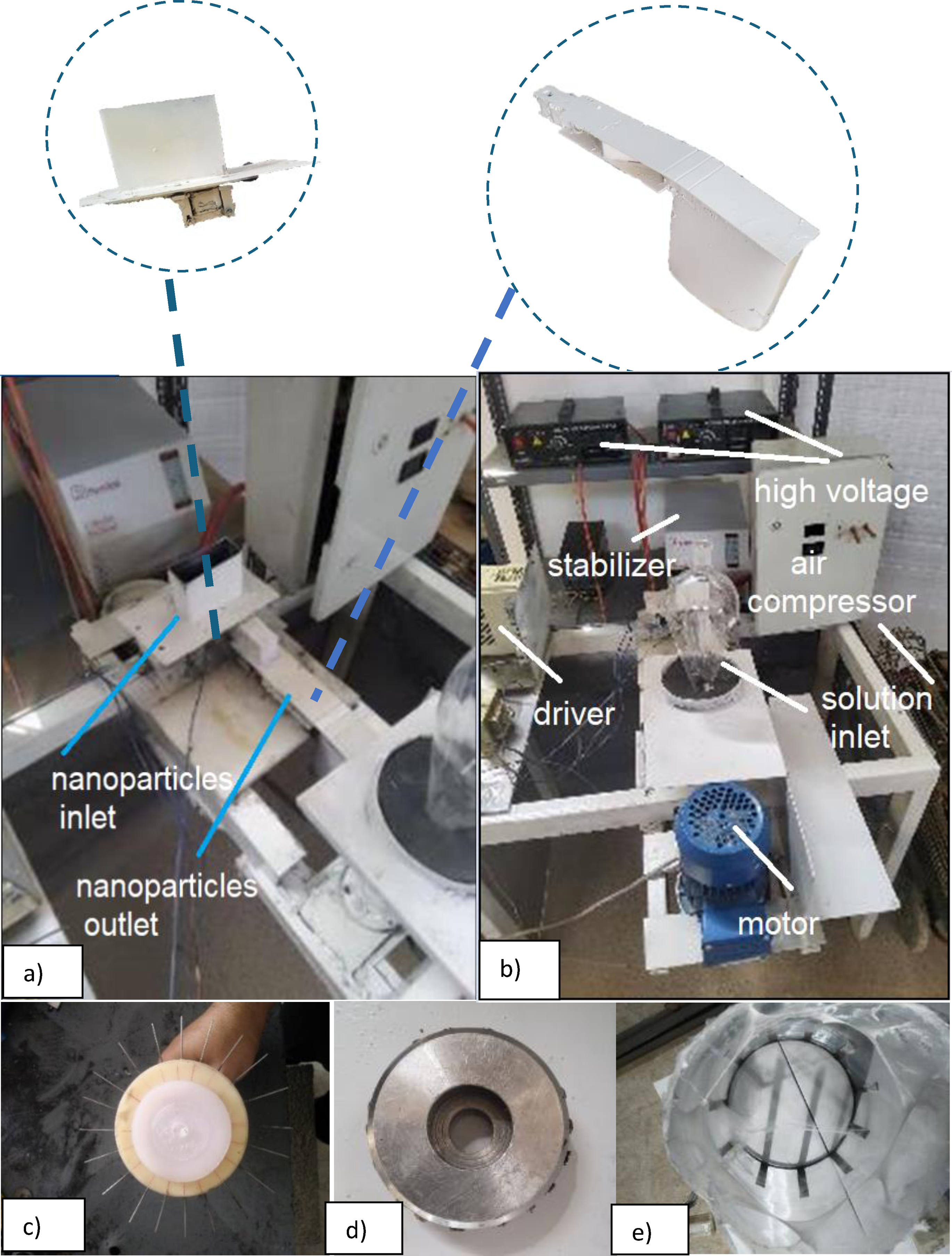
A Schematic view of the overall production system of nanofibrous webs decorated by nanostructures via the dry nanostructure spray system has been demonstrated in Figure 2. A view of the manufactured system has been also illustrated in Figure 3(a)–(e). At first, a nanofiber production system based on the centrifugal method was designed for an initial evaluation of the centrifugal system efficiency. However, regarding the final system’s requirements to be synchronized with the dry nanostructure spray system, such as loading the electrostatic charge required to spray nanostructure on the polymer solution jet, a nanofiber spinning system based on the electro-centrifugal method was designed with different spinning chambers, including 1–20 spinning metallic nozzle (Figure 3(d)) or 1–20 spinning Teflon nozzles (Figure 3(c)), with a maximum rotational speed of 12,000 rpm and the voltage varying between 0 and 30 kV. Each needle length was 40 mm and its diameter was 0.56 mm (with 0.33 mm internal needle diameters). For full production capacity designed with 20 needles, the needle spacing set about 11 mm. Accordingly, the production rate up to 240 g/h based on dry polymer weight (based on a 1 ml/min polymer solution feeding rate for each nozzle and a 20 ml/min polymer solution feeding rate (20 wt.%) for a chamber with 20 nozzles) can be obtained. A continuously movable roll-to-roll collector was designed (schematically illustrated in Supporting information, Figure SIX). The collector area subjected to the production zone at each moment was about 60 cm × 60 cm for continuous web collection at a selected liner velocity of 0–2 m/min. We utilized four needles for each production test due to insufficient materials to prepare and operate the device at full production capacity. Accordingly, the needle spacing was about 55 mm. Based on dry polymer weight, the test production rate was about 48 g/h. The weight of the layer developed here was around 50 g/m2, and the web formed was about 60 cm by 60 cm in size for each test period of about 22 min. The test production rate was about 48 g/h based on dry polymer weight ((based on 1 ml/min polymer solution rate for each nozzle, i.e., 4 ml/min polymer solution rate (20 wt.%) for each chamber with 4 operating nozzles). The area weight of the layer formed here set about 50 g/m2 and the web formed was about 60 cm by 60 cm in size for each test period of about 22 min. Schematic view of the overall production system of nanofibrous webs decorated by nanostructures via the dry nanostructure spray system: (1) Rotary spinning unit (also see, Supporting Information, Figure SVIII), (2) nanostructures dispersing unit, (3) collector, (4) motor, (5) high voltage power source, (6) compressed air source, and (7) rotation transmission belt. (a) and (b) A view of the electro-centrifuge spinning system and the simultaneous spraying system of nanostructures; (c) initial spinning chamber; (d) final spinning chamber; (e) nanofibers resulting from centrifugal spinning on the initial design collector.
Integration and synchronization of spray system with electro-centrifugal spinning
Two other challenges must be overcome for efficient synchronization of the nanostructure spray system with electro-centrifuge jet spinning. The first point is that, the nanostructures should impact the solvent-containing polymeric jet with proper kinetic energy to create an appropriate surface penetration and efficient attachment to the jet surface. The second issue is that, the nanostructures should not be placed freely on the dried surface of fibers collected on the collector. To tackle the first challenge, the output cross-section of the dry nanostructure spray system was considered larger than its input cross-section to adjust appropriate kinetic energy. To address the second issue, the electrical charge of the nanostructures and the substrate was set to negative, while the electrical charge of the polymer jet was set to positive, increasing the nanostructures’ tendency to the polymer solution jet and decreasing their tendency to the substrate. Figure 2 illustrates a schematic of this system. Figure SX. (Supporting information) also illustrates a schematic view of the challenges involved in synchronizing the solvent-free dry nanostructure spray system with the electro-centrifugal jet spinning system to single-step in-situ decorating fine nanofibers during the fiber production by the integrated system and the proposed solutions. As can be seen in the schema, after exiting the channel, the nanostructures are exposed to a turbulent airflow, which is caused by the dynamic motion of the spinning chamber. The momentum of the nanostructures needs to be optimized to overcome the turbulent airflow and to reach a desired distance (d) for attraction into the polymer solution jet due to the coulombic force. If the momentum is too large, it may overcome the coulombic attraction force and not properly attach to the surface of the solvent-containing polymer jet or it may move towards the collector (although the electrostatic repulsion force, we designed for the collector by applying a negative surface charge for both nanostructures and collector, prevents it from reaching the collector surface), and if it is too small, it is scattered by the air turbulence and does not reach the polymer solution jet.
Evaluating the performance of the synchronized system
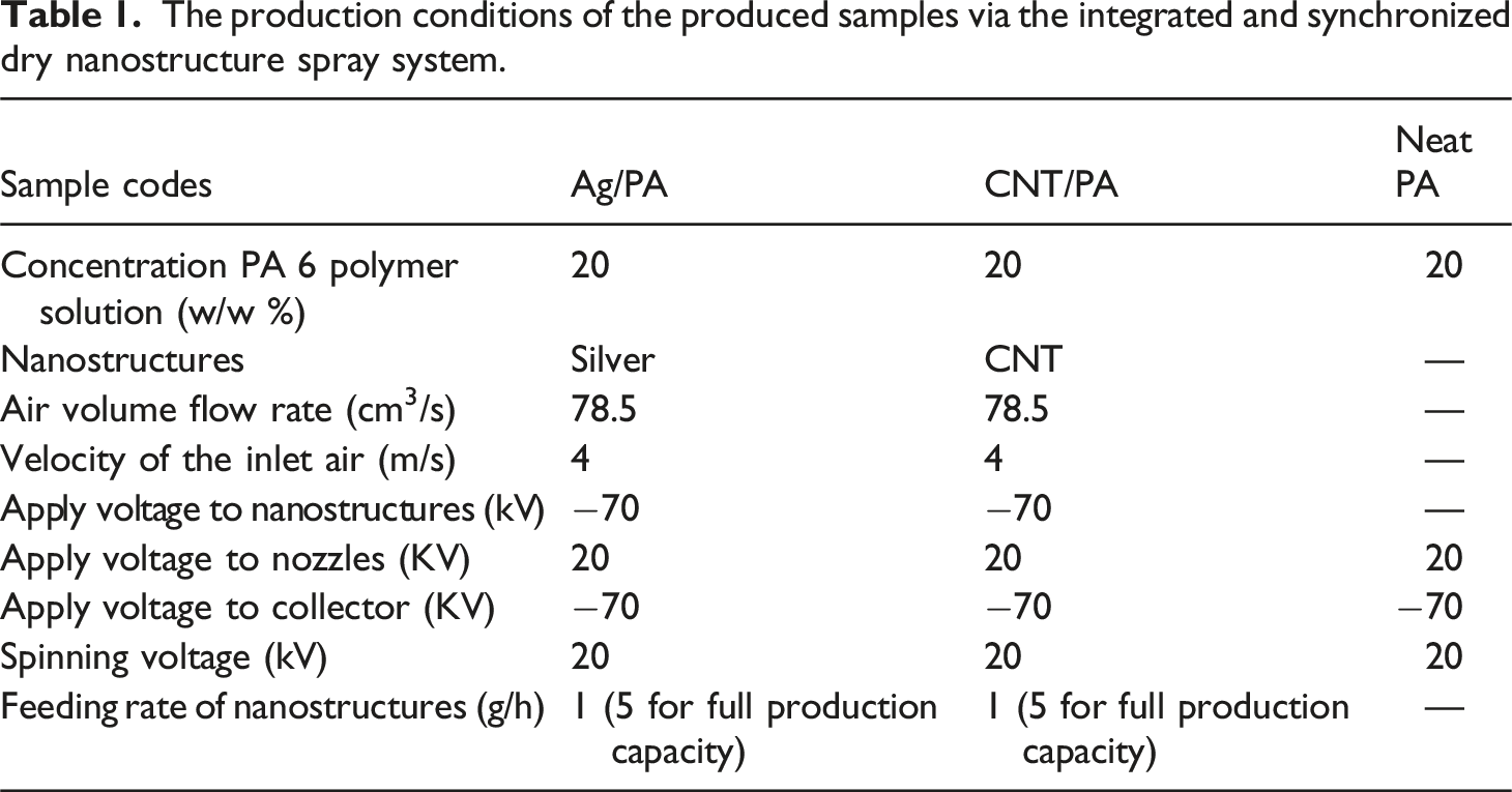
The production conditions of the produced samples via the integrated and synchronized dry nanostructure spray system.
Comparative analysis of nano-colloidal polymer solutions versus integrated dry spray system
The processing of the nanocolloidal polymer solutions is also considered in this section to compare the surface modification characteristics developed in this research, through a synchronized integrated dry nanostructure spray system for simultaneous production and surface modification of nanofibers, with a bulk modification method. For the production process of nano-colloidal polymer solutions, silver nanoparticles, and carbon nanotubes were dispersed with a weight ratio of 3 wt.% of dry polymer in a solution of 20 wt.% polymer in formic acid and were homogenized under an ultrasonic probe for 10 min with a frequency of 60 kHz to produce a colloidal polymer solution for processing nanocomposite nanofiber (bulk modification). Then, the solution was stirred using a magnetic stirrer for 24 h. The fully homogenized solution was poured into the feeding zone of the spinning system, and then nanofibers were spun with the same conditions, including a voltage of 20 kV and a rotational speed of 4500 rpm.
Simulating dispersant unit of nanostructures
Fluent (2020 R2) software was used to simulate airflow through the dispersant unit, and ICEM software was used to make the duct. A three-dimensional computational fluid model was developed using FLUENT. The boundary conditions were defined as a no-slip condition on walls, fully developed flow at inlet/outlet, and steady-state flow. The flow was simulated in a turbulent regime with Reynolds numbers exceeding 2300.
Characterization
Field emission scanning electron microscopy (FE-SEM)
The samples were coated with gold for 200 s using a physical vapor deposition (PVD) sputtering system. Then, the coated samples were evaluated with the FE-SEM MIRA III model manufactured by TESCAN Company, Czech Republic.
X-ray diffraction (XRD) evaluation
XRD device XDM300 model made by ASENWARE company, UK., equipped with Cu anode tube was used to evaluate the presence of silver nanoparticles on three samples of nylon nanofibers without nanostructure, silver nanoparticle-decorated nanofiber, and the composite silver/nylon nanofiber (produced via bulk modification) in 2Ɵ angle ranges of 30°–80° with the step of 0.05°/s degree over the whole 2Ɵ ranges.
Investigating the adsorption kinetics and isotherms of the samples produced by the devised system
To investigate the adsorption kinetics, the concentration of dye solution was measured from the beginning of adsorption until reaching equilibrium using a spectrophotometer. Samples cut in 20 mg of nylon nanofibers without nanostructure, nylon nanofiber decorated with carbon nanotubes, and composite nylon nanofiber with CNT were considered for this evaluation. To this end, the samples were treated in a 10 ml methylene blue (MB) dye solution with an initial concentration of 5 ppm. The average values of triplicate measurements were checked in terms of fitting with the PSOM model (equation (1)). The samples of neat PA, decorated CNT, and composite CNT were treated with the methylene blue (MB) dye solution with initial concentrations of 5, 12.5, 25, 50, 200 ppm for 48 h (until reaching equilibrium). The average values resulting from triplicate spectrophotometric evaluations of the dye solutions were considered to determine the adsorption isotherms. To this end, the results were checked in terms of fitting with Freundlich and Langmuir adsorption isotherm models (equations (2) and (3)).
35
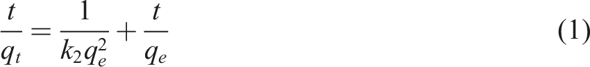


In equation (1), qe, qt, and t represent the amounts of adsorption at equilibrium, the amounts of adsorption at time t, and time, respectively, and k2 indicates constant adsorption values of the pseudo-second-order model (PSOM). In equation (2), kf, n, ce, and qe indicate constant adsorption values of the Freundlich model, affinity coefficient, pollutant concentration in equilibrium, and amount of absorption per unit weight of adsorbent in the equilibrium, respectively. Moreover, qmax and b in equation (3) represent the maximum amount of adsorption of an adsorbent and the affinity of the adsorbed substance to the adsorbent, respectively. To calculate the adsorption isotherm parameters, we plot the data qe versus ce and to calculate the adsorption kinetic parameters, we plot the data t/qt versus t.
Evaluation of the stability of the nanostructures on the nanofibrous membrane
The stability of silver nanoparticles on the surface of the nanofiber was assessed to calculate the proportion of the attached nanostructures. For the elemental analysis, we use inductively coupled plasma spectrometry (ICP-OES). 36 A section of the nanofiber web decorated with nanostructures was dried in an oven set at 50°C for a whole day. After reaching constant weight through alternate weighing the dried sample was dissolved in 30 mL of formic acid for 48 h. Then, it was well homogenized using an ultrasound homogenizer, diluted ten times and homogenized again. The silver concentration in the solution was measured using ICP-OES. The amount of silver nanoparticles on the decorated web with the nanostructures was accordingly calculated. 37
0.1000 g of the cut-dried nanofiber web was shaken with 60 rpm in 5 ml of distilled water for 72 h in a sealed flask. The treated membrane (termed WAg) was also removed after 72 h, dried, and solved in acid to be subjected to the above-mentioned silver content analysis to exactly determine the percentage of attached nanostructures. The silver concentration released in the water was also measured using ICP-OES. This value represents the amount of nanoparticles that have leached out from the nanofibrous membrane during these 72 h. This value was considered the free nanostructures. In fact, the free nanostructures are not more than this value.
The average values resulting from triplicate measurements were considered to calculate the total percentage of silver in the nanofibrous membrane and the percentage of free nanostructures. As a control, a suspension of the silver nanoparticles was also prepared with a known concentration of 5 ppm in distilled water. This solution was also analyzed using the ICP-OES to determine the possible errors involved. The percentage of silver nanoparticles leached out from the decorated membrane with the nanostructures was accordingly calculated based on the initial nanostructure content, the residue nanostructure content on the membrane measured after 72 h of leaching, the effluent concentration (the leached-out nanostructures during these 72 h), the weight of the nanofiber membrane, and the errors percentages.
We also looked at the influence of a simple spray coating on the durability of nanostructures because it is simply linked to the nanofiber manufacturing method. As cross-linkable polysiloxane (XPs) resin treatment has been discovered to be one of the best methods to guarantee the nanostructure’s stability, 38 we designed a simple spray coating with XPs. To do this, nanofiber web cuts were sprayed with a solution of 1 g XPs in 20 ml distilled water. The spray was delivered at a 90° angle from 10 cm above the sample and adjusted to achieve a 100% pickup. Then, the coated samples were dried. The stability measurement protocol described above was repeated on the resin-coated nanofiber samples (coded RAg).
Results and discussions
The continuous integrated production system of nanofibers decorated with nanostructures
The continuous production system of nanofibers decorated with nanoparticles was well-designed and manufactured. A chamber with a capacity of 30 ml has been designed and linked to a polymer solution container to guarantee a constant volume of the polymer solution through the spinning process. The production rate of each spinning chamber with 20 nozzles was estimated at 20 ml/min. The measured rate is calculated at 1 ml/min for each nozzle. Considering an electrospinning nozzle at a laboratory scale with a maximum feeding rate of 1 ml/h, each nozzle here produced at least 60 times more than laboratory scale. Thus, with 20 spinning nozzles, each spinning chamber produces 1200 times greater than an electrospinning system at the laboratory scale. Moreover, for reaching the same fiber diameter (about 150 nm on average) the flow rate at the laboratory scale should usually be set below 0.5 ml/h. Accordingly, the production rate of the system manufactured here has been enhanced by more than 2400 times as compared to that of the lab-scale one. The value is also 480 times greater for a test production with 4 active spinning nozzles. Therefore, the manufactured system here is considered an industrial-scale system. On the other hand, several spinning chambers may be designed in a production line. On the other hand, if we would like to compare our system to other reported mass-production nanofiber systems, it may be referred to Xiong et al. 2021, 39 in which the rate of production of dry nanofiber from each head can be calculated at 13.7 g/h as compared to that of 240 g/h (48 g/h for 4 working spinning nozzles) for our system. Consequently, the rate of production via our system can be up to about 20 times greater than that of the reported mass production scale. On this account, it can be confidently called a mass production or industrial scale system and its production rate is remarkable for a nanofiber production system by setting several spinning chambers in a production line as is usual in fiber spinning lines.
It is noteworthy that this technique offers a pathway towards a new era of developing versatile products using different polymers, polymer mixtures, solvents, co-solvents, additives and different formulations of polymer solutions, and also different nanostructures and combinations thereof. Each of these products for each approach or application can be considered as a novel research topic and then still need some investigations to be optimized, based on the fundamentals reported in this research. There are remarkable potentialities for this innovation, for instance, for the investigation of additional nanostructures and other polymer solutions for various applications.
To enhance the coating quality and uniformity of nanostructures, it can be beneficial to design and develop a custom nozzle that is compatible with the geometry and configuration of the spinning chamber. Furthermore, production parameters can be set for more cost-effective products for various polymer solutions and nanostructures. For example, accurate evaluation of the effect of air inlet velocity on nanostructure dispersion requires the use of a particle counting system. Other parameters such as process parameters including nanoparticle dispersion parameters (e.g., nanoparticle feed rate, air pressure, applied voltage), spinning system parameters (e.g., rotational speed of spinning chamber, applied voltage, needle diameters), etc. can be investigated to improve the uniformity of nanofiber coating. Nanoparticle adhesion mechanisms can be studied by investigating the volatility of different solvents, thus enabling the evaluation of system performance for different nanoparticles.
Results of simulating air flow in nanostructures’ dispersant system
In order to disperse nanostructures, charging them and blowing compressed air have been used to overcome the surface-free energy of nanostructures. Six different mechanisms were considered to spray and create a suitable dispersion of bulk nanoparticles including the Coulombic repulsion force, drag force, impact effects, eddy (here, air vortex) flows effects, turbulent fluctuations, and velocity gradients (shearing force).
Simulating air flow in nanostructures’ dispersant system has been illustrated in Figure 4(a)–(f). Figure 4(a) shows the duct, its designed geometry, and the direction of air flow inlet and outlet, and Figure 4(b) shows the velocity contour in the designed duct. In the designed system, the dispersing process occurs in different stages. In the first stage, bulk nanostructures are separated with vibration by passing through the vibrating charged metal mesh. In the next stage, as seen in Figure 4(c), a high-speed airflow (with a maximum velocity of 18 m/s based on fluent software calculations) blows to the nanostructures as it reach the venturi channel. This flow imposes a surface drag force on the bulk nanostructures which can cause a high dispersion rate in this zone. Nanostructures enter a spiral channel that creates large eddy flows. In this zone, the speed is reduced, and eddy flows and wake effect (Figure 4(d) and (e)) are more prominent, which results in two positive effects. Efficient charging of nanostructures (which itself is a key factor for more dispersion of nanostructures and also mixing and homogenization of nanostructures when feeding more than one type of nanostructures is desirable simultaneously). Simulation outputs: Computational fluid dynamics analysis of the nanoparticle dispersion system using the k-ε model in ANSYS Fluent: (a) Duct; (b) velocity contour in the entrance section of the duct; (c-f) movement path of velocity vectors in the entire path of the channel (for more resolution please kindly see the supporting information, Figures SIII and SIV).
Finally, nanostructures travel slowly due to the channel’s increased cross-section diameter, which has been tuned for effective transmission of nanostructures with opposing electric charges to the surface of the polymer solution jets. This tube profile shape supporting the enlarged cross-section diameter is meant to lower the kinetic energy of charged nanostructures to predominate the influence of electric charge as the key force driving the attachment of nanostructures on the polymer jet.
FE-SEM results
As mentioned, the devised system has been evaluated via the production of PA nanofiber decorated with isotropic and anisotropic nanostructures. Micrographs obtained via FE-SEM shown in Figure 5(a) and (b) recorded carbon nanotubes and Figure 5(c) and (d) depicted silver nanoparticles as nano-scale structures on nanofibers. In some points nanotubes are arranged in the form of continued finer fibers on the nanofiber surfaces. Accordingly, the porous structure was offered by intra/inter CNT cavities on the nanofibers with uncovered carbon nanotubes. In this way the nanostructures were not fully covered by the polymer layer, and their cavities were not blocked via diffusion of the polymer molecules. On this account, the highest level of porosity, the surface accessibility, and the specific surface area can be provided for various applications such as adsorption, cell interaction, and so forth. FE-SEM micrographs of the produced samples by the integrated and synchronized dry nanostructure spray system with the fiber spinning system invented in this research for in-situ surface modification and attachments of dry nanostructures into the surfaces of nanofibers: (a) and (b) CNT/PA nanofibers (the magnification is 200,000, the scale bar is 200 nm, and field of view for a is 1.04 μm, the magnification is 25,000, the scale bar is 2 μm and view field is 8.3 μm for (b)), (c) and (d); Ag/PA nanoparticles nanofibers (the magnification is 100,000, the scale bar is 500 nm and view field is 2.08 μm for (c), the magnification is 50,000, the scale bar is 1 μm and view field is 4.15 μm for d; for more resolution please kindly see the supporting information, Figures SV and SVI); (e) fiber diameter distribution diagram for CNT/PA sample (Average diameter = 141 ± 75 nm); (f) fiber diameter distribution diagram for Ag/PA sample (Average diameter = 151 ± 74 nm).
The fiber distribution diameter diagrams for the produced decorated samples have been illustrated in Figure 5(e) and (f). The average diameter values of the fibers (based on 100 measurements for each sample) have been estimated at 151 ± 74 nm, 141 ± 75 nm, and 140 ± 68 nm for Ag/PA 6, CNT/PA 6 and pure PA 6, respectively. According to statistical analyses with a 95 % confidence level, there is no significant difference between the produced samples in this regard, which indicated that the spray process did not affect the fibers diameter.
As seen in Figure 6(a) and (b), the micrographs of silver nanoparticles in the composite sample show that they are covered by a polymer layer, resulting in low accessibility. Besides some particles are enveloped with the bulk polymer matrix and could not be incorporated on the surface. Figure 6(c) and (d) indicated higher accessibility of carbon nanotubes in comparison with silver NPs, but lower accessibility than that of the integrated dry nanostructure spray system provided. Moreover, their cavities have been filled by diffusing polymer molecules or have been blocked by a polymer layer coverage. Field emission electron microscope images recorded for the nanocomposite nanofibers processed from a nano-colloidal polymer solution: (a) and (b) Fibers containing silver nanoparticles (view field is 8.30 μm and 2.08 μm, respectively); (c) and (d) fibers containing carbon nanotubes (view field is 1.04 μm and 2.08 μm, respectively).
In fact, this innovative system prevents covering nanostructures with a polymer layer, also filling their intra/inter cavities by polymer diffusion or blocking them by a polymer layer coverage. Nanostructure surface features such as their interactions, surface charge, surface tension (including wetting behavior), interfaces, activities (e.g., bioactivity, photocatalytic activities), etc. are not affected by the polymer coverage. Moreover, this technique does not involve the limitations and requirements associated with colloidal solutions procedures (e.g., long-time/harsh homogenizing, using surfactant, solvents, co-solvents, etc.); also, polymer dissociation during homogenizing of the nano-colloidal solution and side-effects on the nanofiber size or morphologies (e.g., bead formation, nano-fiber crystallinity, tenacity, etc.). Besides, it prevents the possible side effects of solvent on nanostructures (e.g., oxidation) and also blocking nanostructures into polymer crystals (forming co-crystals).
Results of X-ray diffraction (XRD)
As seen in Figure 7, the X-ray diffraction pattern of the sample decorated with silver nanoparticles via the integrated dry spray system, compared to the X-ray diffraction pattern of the control sample (neat PA) shown in Figure 7, included two crystal peaks, at 2Ɵ of 38° and 44° (indicated by the red sign) associated with the Miller indices lattice planes of (111) and (112).
40
This can be taken as additional proof for incorporating the nanostructures on the fiber surfaces produced via the integrated dry nanostructure system. However, these peaks have not been recorded for the composite sample obtained via the colloidal solution processing. The reason can be attributed to the oxidation of silver nanoparticles in the formic acid solvent used as the processing disperse media.
41
XRD pattern for pure nylon (PA) nanofibrous web, Ag/PA nanofiber sample produced by the integrated and synchronized dry nanostructure spray system with the fiber spinning system invented in this research to in-situ surface modification and attachments of dry nanostructures into the nanofiber surfaces and XRD pattern for nylon nanofiber sample and silver nanoparticles produced via bulk modification (composite processed via colloidal solution).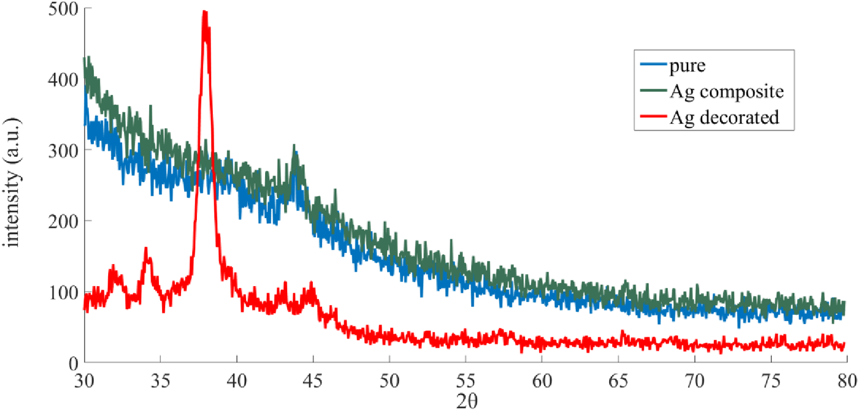
Results of kinetics and isotherms adsorption
The diagrams fitted with the absorption models are shown in Figures 8 and 9. Calculated constant values for the pseudo-second-order (PSOM) model have been reported in Table 2. The high R-square value of 0.995 for all samples suggests a significant relationship between the experimental data and the pseudo-second-order (PSOM) model. This shows that the PSOM model accurately predicts the kinetics of methylene blue absorption in all samples (Figure 8). The CNT-decorated nylon nanofibers (qe = 2.34) sample had the maximum absorption capacity for methylene blue, demonstrating that CNT decoration improves the ability of the nanofibers to absorb the dye. Furthermore, the similarity of the absorption rate of the composite sample with the neat one once more confirmed the lack of nanostructure features on the surface because the CNTs had been covered by at least a polymer layer in the composite sample. Fast absorption kinetics and the maximum absorption constant k2 correspond to the nanofibrous sample decorated with CNT suggesting that CNT and methylene blue have a strong interaction because of π-π bonding, the hydrophobic, and electrostatic interactions. Diagrams of fitting methylene blue (MB) dye adsorption kinetics for the produced nanofibrous membranes via the integrated and synchronized dry nanostructure spray system in comparison with the nanocomposite sample. Diagrams of fitting methylene blue (MB) dye adsorption isotherms for the produced nanofibrous membranes via the integrated and synchronized dry nanostructure spray system in comparison with the nanocomposite sample. Calculated constant values for adsorption kinetic.


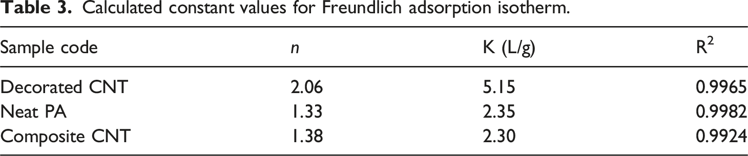
Calculated constant values for Freundlich adsorption isotherm.
Calculated constant values for Langmuir adsorption isotherm.

The results of investigation adsorption isotherms revealed that the Freundlich isotherm showed a better-fitting for the CNT decorated sample, with a higher R-squared value. This implies that the adsorption process was probably conducted by the heterogeneous surface interactions and multi-layer adsorption. The Freundlich model posits a non-uniform surface with varying binding energies, which is consistent with the better fit observed in this case. Since the carbon nanotubes were completely deposited on the surface of the nanofibers, they can provide a heterogeneous surface with different absorption properties compared to the nanofibers. Consequently, the surface of the CNT-decorated nanofibers is anticipated to have different binding sites with variable affinities for the adsorbate, reflecting the absorbent sample’s bicomponent surface feature. The Freundlich model suggests multi-layer adsorption, in which adsorbate molecules create numerous layers on the surface of the adsorbent. This mechanism may be influenced by factors such as the size, shape, and interactions of the adsorbate with previously adsorbed molecules. Both models show excellent fits for neat PA nanofibers. While the Langmuir model fits better, the adsorption behavior can be described by both models. This shows that the adsorption mechanism is most likely a mix of monolayer and multilayer adsorption, with a significant contribution from homogeneous surface binding. The Langmuir model assumes that the surface is homogenous and that binding sites are uniform. This shows that a neat sample likely has a more uniform surface than a decorated sample, with identical binding energies for the adsorbate, which correlates to the one-component (neat PA nanofibers) structure of the absorbent sample. The excellent fit of both models for composite sample suggests that both monolayer (Langmuir) and multilayer (Freundlich) adsorption mechanisms may be involved. Just like what was recorded for neat PA nanofibers, the Langmuir model slightly outperforms the Freundlich model for the composite sample. In fact, the absorption parameters of the composite sample are considerably closer to the neat sample than that of the decorated sample, indicating that the composite sample has more consistency in terms of the homogeneity of the absorption sites due to its more uniform structure. These results interestingly confirm that the loaded nanostructures into the polymer matrix in the composite samples have been covered by a thin layer of polymer and, consequently, their surface features are not accessible at the surface. The decorated sample has a higher b value than the other samples. This demonstrates a high binding affinity between the adsorbate and the adsorbent surface. Despite the high binding affinity, the qmax value is rather modest due to the aforementioned phenomena.
Stability of the nanostructures on the nanofibers
According to the data obtained from inductively coupled plasma spectrometry of Ag-decorated nanofibers dissolved in the acid solution, the percentage of silver nanostructures on the membrane was estimated to be 1.95%. The stability of decorated membranes (Ag) and the resin-treated membranes (RAg) was determined as 88.49% and 96.06%, respectively. Because we were unsure about the stability of the nanostructures, we also designed the resin-treated samples for this test. However, the findings revealed a high level of fastness and stability for nanostructures. More than 88% of nanostructures are stable even without the resin treatment while providing stability is itself a huge challenge in the field of surface modification of textiles even via multi-step procedures and even by sacrificing many practical features of textiles.
It is genuinely intriguing to reach this high level of stability via this one-step integrated production of fine nanofibers and simultaneous cost-effective green surface modification. It may also be readily enhanced by thermal fusion with a continuous or simple post-thermal process, as well as a simple resin treatment (for instance, spraying a resin). The inquiry on the simple resin treatment effect here was found to be efficient in reducing the free nanostructures to less than 4% through this investigation and can be also optimized more (e.g., by optimizing the resin concentration).
Conclusions
A continuous industrial-scale production system of nanofibers decorated with nanostructures was successfully designed, manufactured and evaluated via integrating and synchronizing an innovative dry nanostructure spray system with an electro-centrifugal jet spinning system for in-situ decorating fine nanofibers with attached dry nanostructures. For this purpose, a system was designed and invented for effective dispersion and spraying of dry powder of nanostructures on the nanometer scale. The system for simultaneous dry spraying of nanostructures on the polymer solution jet was devised based on six mechanisms. Among them, two key mechanisms were the compressed air blowing and electrostatic repulsive force mechanisms. The innovative system was examined and optimized in different stages, and its modified version was finally considered and optimized to be integrated into the fiber production system. The performance of the synchronized manufactured system was investigated via the production of nylon nanofibers decorated with two different types of isotropic and anisotropic nanostructures including silver nanoparticles and carbon nanotubes. The produced samples were also evaluated in different terms. The FE-SEM micrographs indicated that nanostructures have been delivered to the fibers in nano-scale and well-dispersed on the nanofiber surfaces. The FE-SEM evidence also showed that the nanostructures attached to the fiber surfaces in this way were accessible and offered a highly porous structure on the nanofiber surface. The composite samples obtained from a mixture of nanostructures and the polymer were also compared regarding their morphology and some other features. Results indicated that the decorated samples produced by the integrated system offered a higher porosity and specific surface areas accessible on the fiber surface rather than that of the composite samples. Moreover, the results of dye adsorption evaluation indicated an enhanced affinity for nanofibers decorated with carbon nanotubes due to their porous morphology compared to the nanocomposite samples and the control samples (without nanostructure). Consequently, this successful idea for integrating and synchronizing an innovative dry nanostructure spray system with a fiber spinning system can serve as an inspiring idea and guideline to provide a prosperous pathway with many green approaches such as solvent-free, volatile substances-free, surfactant-free, and waste-free, single-step, purification-free, effluent-free, efficient, and cost-effective modification technique with no side effect on photocatalytic activities, interactions, or different features, e.g., surface charges, chemical, optical, biological, electrical, thermal, or catalytic features, etc. There is considerable potential for this innovation, for instance, for the investigation of additional nanostructures and other polymer solutions for various applications. For example, it is suggested that future studies explore the capabilities of this system in biomedical applications, focusing on tissue engineering scaffolds and drug delivery systems, as well as in environmental filtration using a wider range of nanostructures and biocompatible polymer solutions. The development of these studies could help to a better understanding of the potential of the system and optimization of operational conditions for specific applications.
Supplemental Material
Supplemental Material - An industrial-scale synchronized dry nanostructure spray system integrated into an electro-centrifugal jet spinning for in-situ decorating fine nanofibers
Supplemental Material for An industrial-scale synchronized dry nanostructure spray system integrated into an electro-centrifugal jet spinning for in-situ decorating fine nanofibers by Saeed Derayati and Roya Dastjerdi in Journal of Industrial Textiles
Footnotes
Funding
The authors received no financial support for the research, authorship, and/or publication of this article.
Declaration of conflicting interests
The authors declared no potential conflicts of interest with respect to the research, authorship, and/or publication of this article.
Supplemental Material
Supplemental material for this article is available online.
References
Supplementary Material
Please find the following supplemental material available below.
For Open Access articles published under a Creative Commons License, all supplemental material carries the same license as the article it is associated with.
For non-Open Access articles published, all supplemental material carries a non-exclusive license, and permission requests for re-use of supplemental material or any part of supplemental material shall be sent directly to the copyright owner as specified in the copyright notice associated with the article.