
Abstract
The lower hook mechanism has the characteristics of long motion path, high moving speed and high external disturbance, significantly impacting the weaving efficiency of the fishing net weaving machine. The multi-motor-based lower hook mechanism exhibits higher moving speed and lesser cam wear compared with the traditional lower hook mechanism, but it requires a high-precision and high-robust control system. In this study, we established a dynamic model for the multi-motor lower hook mechanism using the Lagrange equation. Based on this model, we developed a control system using linear extended state observer (LESO) and piecewise integral terminal sliding mode controller (PITSMC). By introducing a piecewise integral sliding surface, PISMC solved the slow convergence issue of linear sliding surfaces and the singularity problem of integral terminal sliding surfaces. Simulation results for the multi-motor-based lower hook mechanism demonstrate that the proposed PISMC outperforms the nonsingular terminal sliding mode controller and the conventional integral sliding mode controller in terms of control precision and disturbance rejection capability.
Keywords
Introduction
The fishing net weaving machine is also called knotted net weaving machine, which is used to weave knotted nets. The double-hook type fishing net weaving machine is the most commonly used knotted net machine in the industry field, which weaves the knots by the cooperation of the upper hook and the lower hook. 1 The lower hook mechanism is one of the core components of the double-hook type fishing net weaving machine, which drags the warps into shuttles by moving along a fixed trajectory. It is characterized by long moving routine and high movement velocity. Moreover, its work requires high positional accuracy and high disturbance resistance. Nowadays, the commonly used lower hook mechanism is driven by mechanical cams, which encounters the problem of cam wear. Meanwhile, heavy load working condition and long transmission chain restricted its moving velocity and positioning accuracy, and further, restricted the weaving efficiency of the fishing net weaving machine.
Few studies are focusing on the lower hook mechanism, most of them centered on the design and optimization of mechanical cams. 2 With continuous societal progress and the increasing demand for knotted nets, this type of mechanism is increasingly insufficient to the social requirements. For this reason, a kind of multi-motor-based lower hook mechanism is put forward, 3 which is synchronously driven by four permanent Magnet synchronous motors, and controlled by electronic cams instead of mechanical cams. With this improvement, the running speed and the control precision of the lower hook mechanism can be improved, and the cam wear can be eliminated. However, this improvement raises high demands on the control system. The external forces on the lower hook mechanism vary rapidly and randomly, to overcome the external disturbance and finish the working process without collision, the control system must be high-precision and high-robust. The most common form of servo motor controller applied in the industry is PI controller.4,5 With the steady development of control technology, controllers such as active disturbance rejection control, 6 H-infinity control, 7 optimal control, 8 model predictive control9,10 and sliding mode control gradually emerged and applied to the control of servo motors. Among these, sliding mode control is increasingly being adopted and promoted benefitting from its advantages of fast response and insensitivity to external disturbances. Applications include the inverted pendulum system, 11 power systems,12,13 industrial robots, 14 quadrotor UAV 15 and servo motor speed control system. 16
The build of the sliding mode controller requires a complete state of the controlled system. However, some state variables are commonly inaccessible in most systems. As for the servo motors, we commonly have access to their real-time angles only, but their angular velocities and angular accelerations that are required on the construct of sliding mode controller are commonly cannot directly obtained. For this reason, observers such as extended state observer (ESO)17,18 and sliding mode observer (SMO) 19 are often used to supplement the inaccessible system states. SMO has a high dynamic response but typically requires precise mathematical model of the controlled system and high computational resources, while ESO is less dependent on the model and consumes fewer computational resources, but its parameter tuning requires substantial experience and experimentation. To address this issue, a linear extended state observer was proposed, 20 which reduced the number of tuning parameters and simplified the tuning complexity.
The design of sliding surface significantly impacts the control effect of sliding mode controller. Linear sliding surface is the initial form of sliding surface, which encounters slow convergence issues when the system approaches the sliding surface and is thus inadequate for occasions with high precision requisition. 21 Increasing the gain of the switching function can mitigate this issue to some extent, but an excessively high switching gain will exacerbate the chattering problem of the controller. Terminal sliding surface provides finite time convergence, 22 while conventional terminal sliding surface also encounters singularity issue, 23 for this reason, studies24,25 imported nonsingular terminal sliding surface, which solves the singularity issue by applying globally bounded control laws. Integral sliding surface is another approach to improve the system convergence.26,27 This surface ensures that the system always remains on the sliding surface, thereby guaranteeing system stability. However, due to the inherent lag problem, traditional integral modulo often brings about overshooting, negatively impacting the control effect of the integral sliding mode controller. 28 Additionally, some studies introduced piecewise surfaces, which address the system nonlinearity by applying different sliding surfaces to different regions, thus optimizing the controller’s performance. The piecewise approach can be applied to various types of sliding surfaces, such as piecewise integral sliding surfaces, 29 piecewise linear sliding surfaces 30 and piecewise terminal sliding surfaces. 31
This study first established the dynamic model of a multi-motor-based lower hook mechanism using the Lagrange Equation, then, on this basis, developed and applied a sliding mode controller suitable for the motors of the mechanism. This controller employs linear extended state observer (LESO) for real-time observation of the system states, and a kind of piecewise integral terminal sliding surface to ensure fast system convergence and avoid singularity issues. A Lyapunov function is introduced to verify the stability of the proposed controller. Finally, the control effect of the proposed controller is validated by an Adams-Simulink joint model and a fishing net weaving machine platform. Simulation and experimentation results suggest that the proposed controller outperforms the three-closed loop PI controller and the non-singular terminal sliding mode controller, on both convergence speed and disturbance rejection capabilities. Additionally, it also overcomes the singularity problem of the integral terminal sliding mode controller.
The rest of this study is structured as follows: Firstly, we present the dynamic model of the lower hook mechanism. Subsequently, we introduce the design of the linear extended state observer and the piecewise integral sliding mode controller. Following that, we apply the proposed algorithm to drive the lower hook mechanism along a given trajectory, testing its tracking accuracy and disturbance rejection capability. Finally, we provide a conclusion in the end of the paper.
Mathematical modeling
Introduction to the lower hook mechanism
Figure 1 shows the 3D diagram of the lower hook mechanism. As is shown in Figure 1(a), the lower hook mechanism consists of two sets drive mechanisms, which are installed symmetrically on both sides of the machine frame, and a lower hook plate combined block. The single-side drive mechanism consists of a vertical motor, a horizontal motor, a vertical swing arm, a vertical connecting rod, a vertical rail, a horizontal swing arm and a horizontal rail. The vertical rail rotates under the control of the vertical motor; the horizontal rail rotates under the control of the horizontal motor. The lower hook plate is connected to both the vertical and horizontal rails through limit blocks on either side, allowing it to move in a plane trajectory driven by these rails. As is shown in Figure 1(b), a row of lower hooks is installed in front of the lower hook plate. The shuttle box of the fishing net weaving machine contains hundreds of shuttles arranged in parallel, each carrying a certain length of weft thread. The appearance of the shuttle is shown in Figure 1(c). The lower hook mechanism controls the lower hook plate to loop the warp threads into the shuttles, thereby completing the knotting operation. 3D model diagram of the lower hook mechanism: (a) Diagram overview; (b) Diagram of the lower hook plate; (c) Diagram of the shuttle.
The lower hook plate follows a fixed trajectory. Figure 2 illustrates the movement process of the lower hook plate during a complete weaving cycle: it starts from the initial position (as shown in Figure 2(a)), moves along the edge of the shuttles to the hooking position, then pauses briefly to wait for the hooking operation (as shown in Figure 2(b)). Next, it carries the warp threads downward along the original path (as shown in Figure 2(c)), Finally, it releases the warp threads with the help of the unhooking plate (as shown in Figure 2(d)), and returns to the initial position, preparing for the start of the next cycle. In this study, the movement of the lower hook from the initial position to the hooking position is referred to as ascent process, and the movement from the hooking position back to the initial position is called descent process. The movement process of the lower hook plate during a weaving period: (a) Initial position; (b) Hooking position; (c) Descent with warps; (d) Unhooking process.
During the ascent process, no loads are acting on the lower hook plate, while during the descent process, there are about 400 warps pull out by the lower hooks, exerting a heavy and swift load on the lower hook plate. The warp tension is deemed as the primary working load and the main source of external disturbances of the lower hook mechanism. In the following sections, the kinematic modeling and the dynamic modeling will be carried out for the lower hook mechanism.
Kinematical modeling of the mechanism
To promote analysis, we transform the lower hook mechanism into a schematic diagram, as shown in Figure 3. In this figure, we define the lengths and angles with the x-axis of each line segment as follows: |AB| as The schematic diagram of the lower hook mechanism.
As can be seen in Figure 3, angles


This solution is inconvenient for calculation and dynamic modeling, so we fit it by a quintic polynomial, which is given as:


Similarly,


The fitting results are shown in Figure 4, the standard deviation of the fitting curves of The fitting results of each angle: (a) 
The coordinate of the lower hook plate can be expressed as

It is noted that, although there is a coupling relationship between the bilateral drive mechanisms, when the positional error of the bilateral motors is small, the influence of one side’s drive mechanism on the other is significantly less than the dynamic impact of the mechanism itself. Therefore, it can be treated as an external disturbance. To simplify calculations, this study will not model the coupling relationship between the bilateral drive mechanisms.
Dynamic modeling of the mechanism
On the basis of kinematic model, this part gives the dynamic modeling of the lower hook mechanism. The dynamic modeling of the mechanism requires knowledge of the mass and the gravitational center coordinate of each component. This study assumes that the gravitational center coordinate of all components are located on the line segment formed by its two connection points. Based on this assumption, we assume the mass of the lower hook plate as
Appropriate simplifications to the model can yield significant improvements in computational speed with a few loss of accuracy. To enhance computational efficiency, this study approximates the horizontal structure into 4 mass points located at point A, point B, point C and point F. Since point A and point F are fixed, we only need to consider point B and point C. Assume the equivalent mass of point B and point C as


This study models the lower hook plate using the Lagrangian equation, which can be expressed as


The expressions of all associated variables are provided in the appendix.
By defining external loads of the vertical motor and the horizontal motor as

The dynamic equation of each servo motor can be obtained by the Newton’s second law as

Nomenclature table of the mathematical modeling.

It is noted that, both the kinetic model and the dynamic model are based on several assumptions: all components are considered rigid structures, and both friction and damping between components are neglected, as well as any clearances between components. While these assumptions reduce the precision of the model to some extent, they still facilitate the overall analysis of the system.
Sliding mode controller design
Linear extended state observer
The application of sliding mode controller requires the real-time dynamic state of each servo motor. We define the angle and the angular velocity of the motor as 

We constructed a vertical observer for the vertical motor and a horizontal observer for the horizontal motor. The angle, angular velocity and angular acceleration of vertical observer are defined as
Slide mode controller design
The design of the sliding mode controller includes two steps, first is the design of the sliding surface, second is the design of the control law. We first consider the design of the sliding surface. By defining 
The integral sliding surface is given as32,33
Substitute terminal sliding surface into integral sliding surface yields the integral terminal sliding surface as

Since 

The continuity of the sliding surface at segmentation points significantly impacts the control performance of the sliding mode. Taking the derivative of equation (27) yields
By substituting the segmentation points
We design a vertical controller for the vertical motor and a horizontal controller for the horizontal motor. The output array is defined as 


This study applies the exponential approaching law to the sliding mode controller, which is given as

Figure 5 illustrates the control structure diagram of the single-side drive mechanism, which incorporates linear extended state observers and piecewise integral sliding mode controllers. This structure includes both a vertical controller and a horizontal controller and is applicable to both the left-side and right-side drive mechanisms. Here Control structure diagram of the single-side drive mechanism.
Stability analysis
The stability of the proposed controller is verified using a Lyapunov function. Prior to this, we transform equation (20) into

Furthermore, substituting equation (36) into equation (29) and replace all redefined components yields
Now, giving the Lyapunov function as
its derivation can be calculated to
Since
Results and discussions
In this section, the proposed algorithm will be verified on both Adams-Simulink joint model and the fishing net weaving machine. The key parameters of the lower hook mechanism are given as:
Assuming the weaving period to 2s, then the target angles of the vertical motor and the horizontal motor can be given in Figure 6. As is shown here, the lower hook plate is driven upwards by servo motors during 0s ∼ 0.96s, which corresponds to the ascent process; and pauses during 0.96s ∼ 1.07s; after that, downwards along the same path during 1.07s ∼ 1.98s, which corresponds to the descent process; finally, stops at the origin point until the end of period. The simulation and experimentation target is to control the motors rotating along their target angles, and reduce the errors between the target angle and the real angle of each motor as much as possible. The target rotational angles of each servo motor during the period.
Simulation results
The Adams-Simulink joint model consists of a simulation model of the lower hook mechanism, which is built in the Adams platform, and a controller module to perform control algorithm and interaction with the simulation model, which is built in the Simulink platform. The simulation model is shown in Figure 7. In this model, each component of horizontal structure and vertical structure is mounted by revolute joint connectors, and the lower hook plate is restricted by contact forces imposed by each guiding rail. Virtual prototype for the lower hook mechanism.
Three Simulink models are built for test and comparison, which are described below: 1. Nonsingular terminal sliding mode controller (abbr. to NTSMC), which applies nonsingular terminal sliding surface given in equation (23). Its parameters are set to 2. Integral terminal sliding mode controller (abbr. to ITSMC), which applies linear sliding surface given in equation (25). Its parameters are set to 3. Piecewise integral terminal sliding mode controller (abbr. to PITSMC), which applies piecewise integral sliding surface given in equation (27). Its parameters are set to
Above all, to intuitively demonstrate the optimization effect of proposed controller, the primary parameters for the ISMC and the PITSMC are set equal. Additionally, All three controllers are applied to exponential approaching law with parameters
The weaving period is set to 2 s. During the upward process, no external disturbances are added, while during the downward process, a sudden load
Figure 8 presents the angular errors of each servo motor during the weaving period. The control performance is evaluated using the root mean square error (RMSE), The RMSE values for the four servo motor across different models are listed in Table 2. As observed from both Figure 8 and Table 2, the performance of ITSMC and PITSMC is nearly identical, and both outperforms NTSMC. For the vertical motor, PITSMC obtained 73.2% decline compared with NTSMC, while for the horizontal motor, the decline rate is 44.3%. Control errors of each simulation: (a) Control errors of the left-side vertical motor; (b) Control errors of the right-side vertical motor; (c) Control errors of the left-side horizontal motor; (d) Control errors of the right-side horizontal motor. RMSE value of each model in the simulation.

From Figure 8, it is evident that when external loads are applied, both ITSMC and PITSMC recover from disturbances within a short time interval, whereas NTSMC requires a longer period to stabilize. For the vertical motor, the average interval from the time the disturbance is introduced to the time the angle error returns to zero for NTSMC, ITSMC, and PITSMC are, respectively, 339 ms, 31 ms, and 30 ms. For the horizontal motor, ITSMC and PITSMC essentially show no significant impact from external disturbances, while NTSMC fails to return to normal levels even after the disturbance is removed. This result indicates that the proposed controller offers better resistance to external disturbances.
Figure 9 illustrates the controller output of the left-side drive mechanism, with Figure 9(a) showing the vertical controllers and Figure 9(b) depicting the horizontal controllers. It can be seen that the overall trends of the three models are similar. However, ITSMC exhibits a sharp change in the output of the vertical controller around t = 0.6s, similar behavior also appears at the output of the horizontal motor around t = 1.35s. This behavior indicates the presence of a singularity problem. In contrast, PITSMC demonstrates a smoother output compared to ITSMC, which is a key advantage of the proposed controller. Controller outputs of each simulation: (a) Outputs of the left-side vertical controllers; (b) Outputs of the left-side horizontal controllers.
In practical working conditions, the primary focus is on the trajectory of the lower hook plate. This study presents the trajectory of the lower hook plate in Figure 10, where Figure 10(a) illustrates the ascent process and Figure 10(b) shows the descent process. From Figure 10(a), it can be observed that, under undisturbed conditions, the lower hook plates of all three models closely follow the target trajectory. Towards the end of the trajectory, NTSMC exhibits a slight deviation from the target, while ITSMC and PITSMC achieve higher accuracy. In Figure 10(b), it can be seen that the external load affects the tracking accuracy of each model. However, the tracking accuracies of ITSMC and PITSMC are significantly better than that of NTSMC. The lower hook plate trajectory of the simulation: (a) The trajectory during ascent process; (b) The trajectory during descent process.
Experimentation results
In this part, the proposed controller is verified in the fishing net weaving machine platform shown in Figure 11. In the industrial applications, the positional control of servo motors is commonly realized by three-closed-loop PI controller. In this experimentation, a PI controller is introduced for comparison, with its parameters adjusted to optimal. Additionally, NTSMC is also introduced for comparison, the parameters of NTSMC and PITSMC are equal to those used in the simulation part. The lower hook plate on the fishing net weaving machine.
The lower hoop mechanism assembled on the fishing net weaving machine shares the same structure and size with the virtual model. The servo motors are controlled by BECKHOFF CX2040 PLC, and communicates with PLC using CANopen over EtherCAT protocol. The weaving period is set to 4s. The experimentation results are given in Figure 12, Figure 13 and Table 3. Control errors of the experimentation: (a) Control errors of the left-side vertical motor; (b) Control errors of the right-side vertical motor; (c) Control errors of the left-side horizontal motor; (d) Control errors of the right-side horizontal motor. Controller outputs of the experimentation: (a) Outputs of the left-side vertical controllers; (b) Outputs of the left-side horizontal controllers. RMSE value of each model in the experimentations.
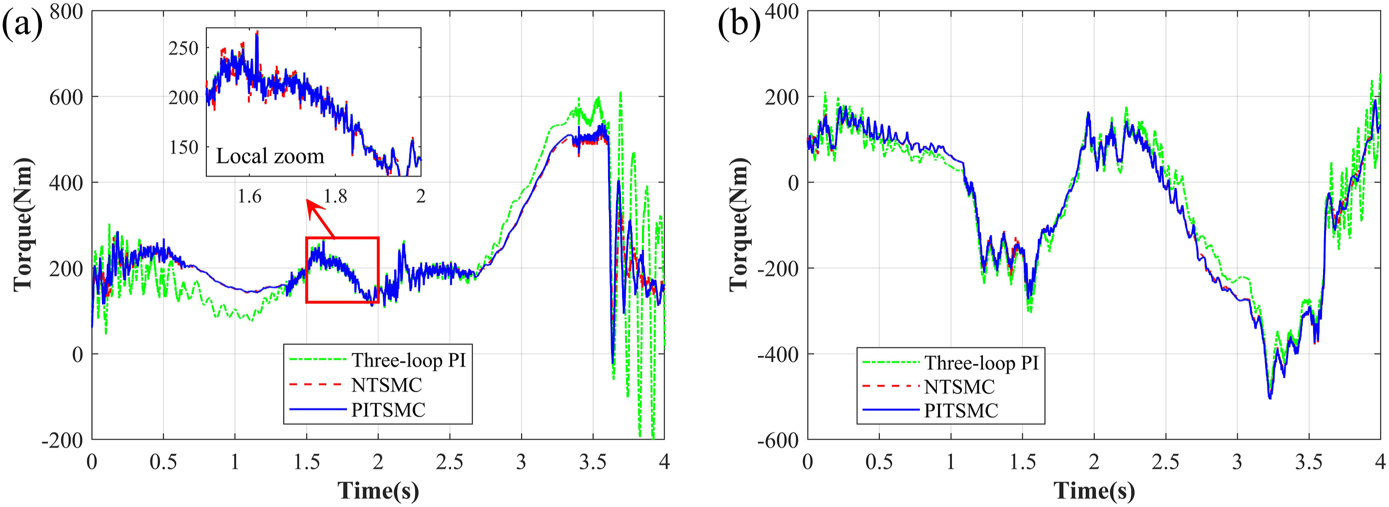

Figure 12 presents the angular errors of each servo motor during the experiment. The RMSE values for the four servo motors across different models are listed in Table 3. For the vertical motor, PITSMC achieves a 72.6% and 84.8% reduction in RMSE value compared to the PI controller and NTSMC, respectively. For the horizontal motor, the corresponding decline rates are 83.9% and 54.1%. It can be observed that the PI controller exhibits noticeable positional errors in some areas of the weaving period and experiences sharp oscillations after the unhooking. NTSMC performs better on the horizontal motor but exhibits significant static error on the vertical motor for most of the period. In contrast, PITSMC demonstrates the smallest tracking errors and the fastest recovery after unhooking, indicating the best tracking performance and the strongest resistance to sudden loads among the three controllers.
Figure 13 presents the controller output of the left-side drive mechanism. As can be seen in the rectangle box in Figure 13(a), both NTSMC and PITSMC exhibit relatively high-frequency oscillations in certain areas, which are manifestations of the chattering phenomenon inherent to sliding mode control. In contrast, the PI controller primarily shows low-frequency oscillations. Moreover, the oscillation amplitudes of NTSMC and PITSMC are smaller than those of the PI controller, and PITSMC does not experience any abrupt changes in control output due to singularity issues.
Conclusion
The multi-motor-based lower hook mechanism has the advantages of high movement speed and the elimination of cam wear, but it demands the controller to be high tracking accurate and high robust. In this study, the dynamic model of the multi-motor-based lower hook mechanism was developed using the Lagrange equation, and sliding mode controllers were applied to each motor based on this model.
The design of the sliding surface plays a crucial role in the effectiveness of sliding mode control. While traditional integral terminal sliding mode controllers can enable fast system convergence, they may also lead to singularity problems. To address this, a piecewise integral terminal sliding mode controller was proposed by combining the integral sliding surface with the terminal sliding surface. This approach achieves high tracking accuracy, strong resistance to sudden loads, and avoids singularity issues. The simulation and the experimental results demonstrate that the proposed controller outperforms the three-loop PI controller and the non-singular terminal sliding mode controller in terms of control accuracy and disturbance rejection, additionally, it also avoids the singularity problem of integral terminal sliding mode controller. This study can enhance the weaving speed and stability of the weaving machine, offering significant benefits for its electrification transformation. Additionally, this study also holds considerable reference value for applications requiring high speed and resistance to external disturbances.
Footnotes
Declaration of conflicting interests
The author(s) declared no potential conflicts of interest with respect to the research, authorship, and/or publication of this article.
Funding
The author(s) received no financial support for the research, authorship, and/or publication of this article.
Appendix
The formula for expressing the associated variables in the modeling process: