
Abstract
The coupling model between unwinding tension and various factors is crucial for understanding warp beam unwinding characteristics and designing tension control systems. However, currently established models are simple and fail to reflect the complexity of the actual unwinding process. Additionally, the traditional unified PID control method for multiple warp beams is difficult to ensure stable unwinding tension for single warp beam, negatively impacting the quality and efficiency of the sizing process. To address these issues, coupling models between tension, radius, speed, turns and air pressure during the warp beam unwinding process were established and validated using constructed detection devices. Experimental results showed that the four types of measured warp beams fit the three coupling models with
Keywords
Introduction
Warp beam unwinding is a critical component of the sizing process. The stability of its tension plays a key role in ensuring the quality of sizing. During unwinding, tension can be easily affected by internal and external factors (such as unwinding radius, unwinding speed, and moment of inertia) to cause fluctuations, which have adverse effects on the final properties of the sized yarn. In practical production, current tension control mode still relies on the traditional unified PID control method for multiple warp beams. 1 Only one tension sensor detects the combined tension and adjusts them collectively. This approach cannot independently control single warp beam. Moreover, PID control has limitations in managing time-varying and strongly coupled tension systems.2,3 As a result, the tension of warp yarns remains uneven after control. Therefore, it is imperative to clarify the unwinding behavior of warp beam and propose new tension control mode to maintain stable tension throughout the entire unwinding process.
At present, Wang 4 and Xiao 5 theoretically and experimentally analyzed the factors affecting the unwinding tension. However, these studies only established simple model related to unwinding tension, leading to an incomplete reflection of the actual unwinding process. For new intelligent tension control method, researchers such as Alkhafaj and Uzun, 6 Li et al. 7 and Zhu et al. 8 combined particle swarm algorithms, neural networks, and fuzzy control with PID control to achieve adaptive tension control in sizing and related fields. In particular, fuzzy control has notable advantages. It applies fuzzy sets and rules for reasoning according to the control experience of production operators or the knowledge of relevant experts to realize precise tension control.9–11 However, the above approaches still use the mode of measuring tension to control tension. Due to space limitations, the sizing machine cannot install independent tension sensors to control tension of single warp beam.
Therefore, this paper aims to address these issues and proposes the following research hypotheses: (1) A coupling model relationship exists between tension and factors such as speed, radius, and brake air pressure. (2) The unwinding turns sensor can be easily installed on each warp beam, enhancing tension control accuracy through real-time monitoring and feedback adjustment. Based on these hypotheses, this paper investigates the tension coupling models and introduces a new tension control mode for single warp beam, verifying the hypotheses through experiments.
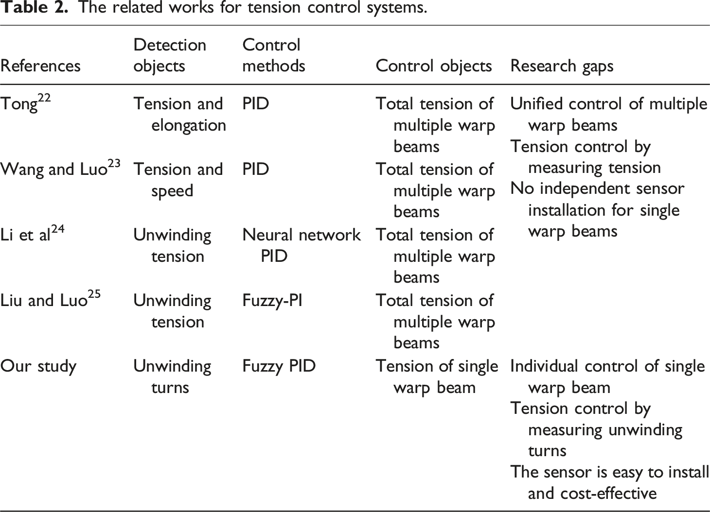
The main contribution of our study is that we first established the coupling models between unwinding tension and various factors and verified them through the experimental data gathered from constructed detection devices. Subsequently, these models are applied to design a novel fuzzy adaptive PID control system to realize the constant tension of single warp beam. The system takes the unwinding length as the control objective and utilizes the unwinding turns detection device to monitor real-time changes in the unwinding process. Finally, the proposed control system is proven to be more effective than traditional PID control through simulations and analysis under varying conditions. Our research presents the following innovations: • Tension coupling models of the unwinding process are developed and validated to provide important theoretical support for optimizing the performance of sizing machines. • A novel single warp beam tension control system is designed to accurately control tension by measuring unwinding turns. The sensor is easy to install and cost-effective. • Based on the coupling models, a fuzzy PID control method is developed to maintain constant unwinding tension for single warp beam under varying conditions.
Literature review
Warp tension, as a key factor in the sizing process, directly affects the quality of the sized yarns.12,13 To achieve stable tension, it is necessary to establish a clear theoretical model that defines the relationship between tension and influencing factors, as well as to design an efficient tension control system. This section reviews previous research on tension theory models and control systems in sizing fields, aiming to identify research gaps and further highlight the innovations of this study.
Tension theory models
Tension theory models play an important role in the field of tension control. These models provide a theoretical foundation that helps to clarify the interactive influences of various factors on tension. 14
The related works for tension theory models.

Tension control systems
Tension control systems are essential in industrial production processes. They keep tension within a preset stable range, thereby improving product quality and increasing production efficiency.19–21
The related works for tension control systems.
Research gaps
The above studies have revealed significant research gaps in the tension theory models and control systems for the unwinding process on the sizing machines, which still require further investigation.
Firstly, previous studies primarily focused on simple tension theory models under static conditions and lacked model validation. The coupling models between the unwinding tension and influencing factors of the sizing machine need to be further improved. In our study, the coupling models between unwinding tension and factors such as unwinding radius, speed, turns, air pressure and yarn characteristics were established through dynamic analysis of the warp beam and yarn. Additionally, five types of detection devices were developed to analyze the behavior of each factor and verify the accuracy of the models. This provides a solid theoretical foundation for innovations in unwinding tension control technology for sizing machines.
Secondly, due to limited installation space, the traditional unified control method of multiple warp beams in sizing machines cannot install independent tension sensors to control each warp beam individually. However, the distinct variations in tension states across each warp beam necessitate further refinement. To address this, we propose a new control mode and method. Through the unwinding turns detection device, the real-time monitoring of the unwinding state of single warp beam is achieved to ensure constant tension for each warp beam. Figure 1 illustrates the traditional and proposed tension control modes. Furthermore, drawing on practical production experience, we designed a fuzzy adaptive PID controller to enhance the system’s intelligence and response speed. This offers strong technical support for optimizing and upgrading the sizing production process. Schematic diagram of the warp beam unwinding process. (a) Traditional control mode of measuring tension to control tension; (b) proposed control mode of measuring unwinding turns to control tension.
Theoretical models
The warp beam unwinding process of the sizing machine involves the simultaneous passive unwinding of warp sheets from the warp beam, encompassing multiple warp beams and yarn guide rollers. Specifically, schematic diagram of the single warp beam unwinding process is shown in Figure 2. The speed difference between the warp beam and the guide roller generates unwinding tension. As the unwinding radius of the warp beam decreases, its rotational speed and number of turns gradually increase. The air pressure of the brake cylinder is automatically adjusted by the warp beam unwinding tension control system to maintain tension stability. To comprehensively understand the interaction and influence between unwinding tension and various factors, it is necessary to establish and validate theoretical couple models for factors such as tension, speed, radius, turns, and air pressure. Schematic diagram of the single warp beam unwinding process. (a) Single warp beam unwinding; (b) empty warp beam; (c) single warp yarn before and after stretching.
Theoretical model 1: Unwinding tension, speed, radius and air pressure
According to Newton’s second law of rotational motion, the dynamic moment balance equation of the warp beam unwinding process at any time 
Specifically, the braking torque 

The moment of inertia of the warp beam 
Then, the radius of the warp beam 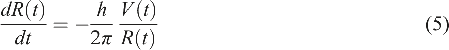

Through the derivation of Equations (1) to (6), the coupling model between unwinding tension and various factors is established:
The expressions of 
To sum up, equation (7) clarifies the coupling relationship between the unwinding tension, tension, speed, radius and air pressure. At the same time, it is shown that the unwinding tension control system is a nonlinear and time-varying system.
Theoretical model 2: Unwinding tension, speed and yarn characteristics
The distance between the warp beam and the guide roll remains constant during the unwinding process, so it is a typical mass flow system. Based on the mass conservation law of the yarn before and after stretching, the model between unwinding tension, speed and yarn characteristics can be written as
27
:
Theoretical model 3: Unwinding speed, radius and number of turns
When the unwinding speed of the warp beam increases, the unwinding radius decreases more rapidly, and the number of unwinding turns accumulates faster. During the circular motion of the warp beam unwinding process, the relationship between these three factors is represented as:
Detection devices and experimental setup
Detection devices and principles
Based on the key factors involved in the aforementioned models, five types of detection devices were constructed, including air pressure, unwinding speed, radius, tension and turns detection devices. Figure 3 illustrates the installation schematic of detection devices on the warp beam. The measuring device and their actual installation are presented in Figure 4. Installation schematic of detection devices on the warp beam. Detection devices and their actual installation. (a) Warp beam measurement with application program; (b) air pressure measuring device; (c) unwinding speed measuring device; (d) unwinding radius measuring device; (e) unwinding tension measuring device; (f) unwinding turns measuring device.
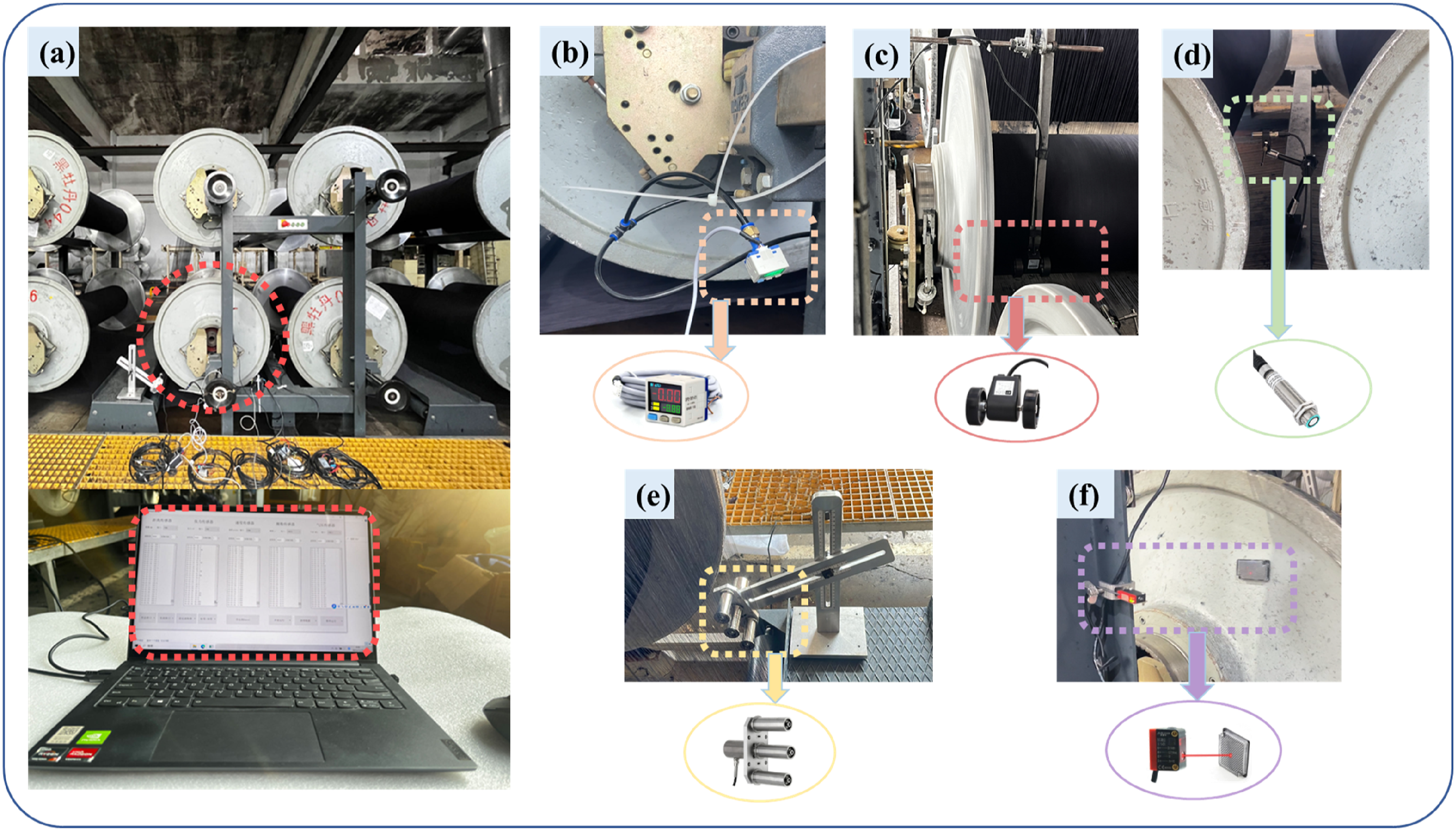
The air pressure sensor is utilized to measure the air pressure of the brake cylinder, with a range of −0.1 to 1.0 Mpa and with an accuracy of 0.2% of full-scale value (FS), as depicted in Figure 4(b). From Figure 4(c), the unwinding speed is accurately determined using the roller speed sensor, which has an accuracy of 0.01% FS and is supported by its fixture. The operating principle is based on circumference measurement, and the diameter of the roller is 64 mm. During the measurement process, the speed sensor is consistently pressed firmly against the warp beam to ensure precision and reliability. In Figure 4(d), the ultrasonic distance sensor, along with the magnetic crab clamp gauge holder fixture, is employed for unwinding radius measurement. This sensor operates by measuring the time difference between the transmission and reception of ultrasonic waves. It has a detection range of 70 to 1000 mm and an accuracy of 0.1% FS. During installation, the sensor is positioned within its sensing range and aligned with the warp beam’s center of gravity.
The three-pulley yarn tension sensor, as shown in Figure 4(e), is based on the resistance-strain measuring principle. It offers a detection range of 0 to 20 N and has a high accuracy of 0.05% FS. This sensor measures the unwinding tension of 10 warp yarns at the leftmost end of the warp beam and then averages the obtained values. Furthermore, the warp sheet tension is derived from the number of warp yarns on the beam. Figure 4(f) illustrates the use of the laser reflection photoelectric sensor along with the tiger clamp fixture to measure the unwinding turns of the warp beam. The laser reflection photoelectric sensor is a widely used non-contact sensor that operates on the principle of detecting the presence or absence of objects through the reflection of a laser beam. Each time the laser beam is reflected, it is counted as one unwinding cycle. It can detect distances up to 0-10 m (with no blind spot), has a response time of 1 ms, and maintains an accuracy of 0.02% FS.
All fixtures utilize magnetic attraction and can be securely affixed to the warp beam frame. To enable simultaneous and real-time data collection from all five sensors, an application program is developed through the Python language with Modbus communication protocol. The serial port and baud rate of the corresponding sensors are set separately to read and save the data.
Experimental materials and methods
The detailed parameters of the measured warp beams.
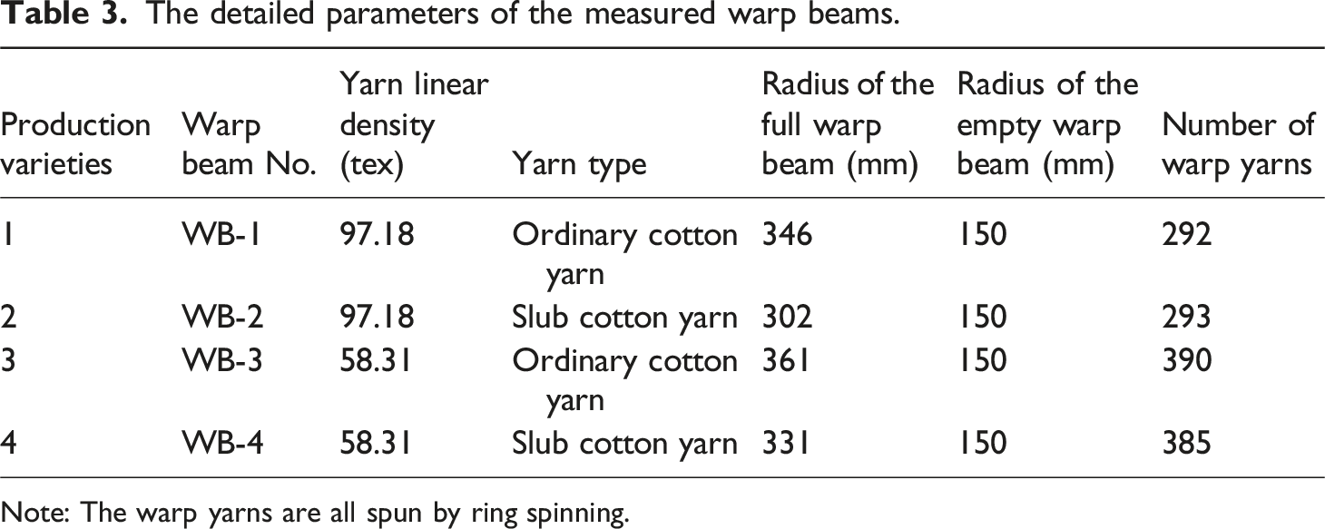
Note: The warp yarns are all spun by ring spinning.
The raw yarns WB-1-Y, WB-2-Y, WB-3-Y, and WB-4-Y on the aforementioned warp beams underwent testing for changes in tension and elongation on the electronic universal testing machine. The stretching speed was set at 250 mm/min, with a distance of 250 mm between the clamps at both ends. During stretching, one end remained stationary while the other end moved until the yarn broke.
Fuzzy PID tension control system and method
The fuzzy PID control combines fuzzy control with PID control. By utilizing the experience gained from production practice and relevant expert expertise, it establishes the fuzzy control rules and then applies fuzzy reasoning to realize the optimal adjustment of PID control parameters. This approach is particularly effective for uncertain, nonlinear, and time-varying tension control systems. The anti-interference ability of the system is significantly enhanced by the time-varying control parameters
Fuzzy PID tension control system
The control schematic of warp beam unwinding tension based on fuzzy adaptive PID controller is shown in Figure 5. It uses the unwinding length as the control target and employs unwinding turns detection device to monitor the real-time unwinding state of the warp beam. This approach differs from traditional tension control systems, which rely on directly measuring tension for regulation. The warp beam unwinding tension control based on fuzzy adaptive PID controller.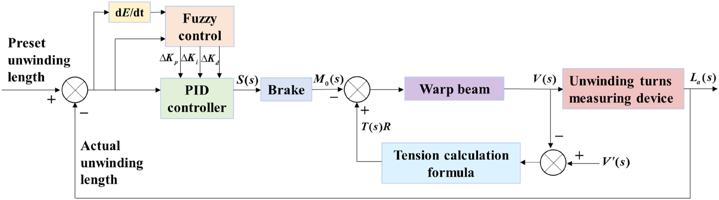
When there is an error between the reference value and the actual value
Therefore, the main components of the control system include computer, fuzzy adaptive PID controller, brake, warp beam and measuring device, as illustrated in Figure 6. Based on their respective characteristics and mathematical models, the transfer function of each control element is derived. Transfer functions are critical tools for analyzing, designing, and simulating control systems. The fuzzy PID control system for warp beam unwinding tension.
The brake is the actuating element. The output braking torque 
The warp beam serves as the controlled object. In Model 1, both unwinding radius and moment of inertia are time-varying parameters, which are related to the thickness of the yarn 
The measuring device utilized is a laser photoelectric sensor. The actual unwinding speed is obtained by detecting the unwinding turns of the warp beam (Model 3). The relationship between the unwinding speed and unwinding length is integral. Thus, the transfer function of the detection device can be described as:
The relationship between unwinding tension and speed is expressed in Model 2. The transfer function is derived through the application of Laplace transformation to this model, which can be expressed as:
Fuzzy PID control method design
The core of the fuzzy adaptive PID control lies in utilizing the fuzzy controller to adjust the PID control parameters online.
28
It can be stated as follows
29
:
The fuzzy adaptive controller can be described as
30
:
Generally, the implementation of a fuzzy controller consists of three main steps: input fuzzification, establishment of fuzzy control rules and defuzzification of the output.
Fuzzification
The process of fuzzification is to convert precise inputs into fuzzy sets through the membership functions of linguistic variables and their corresponding linguistic values. Specifically, the linguistic variable of
The linguistic variables of The membership functions for input and output linguistic variables. (a) 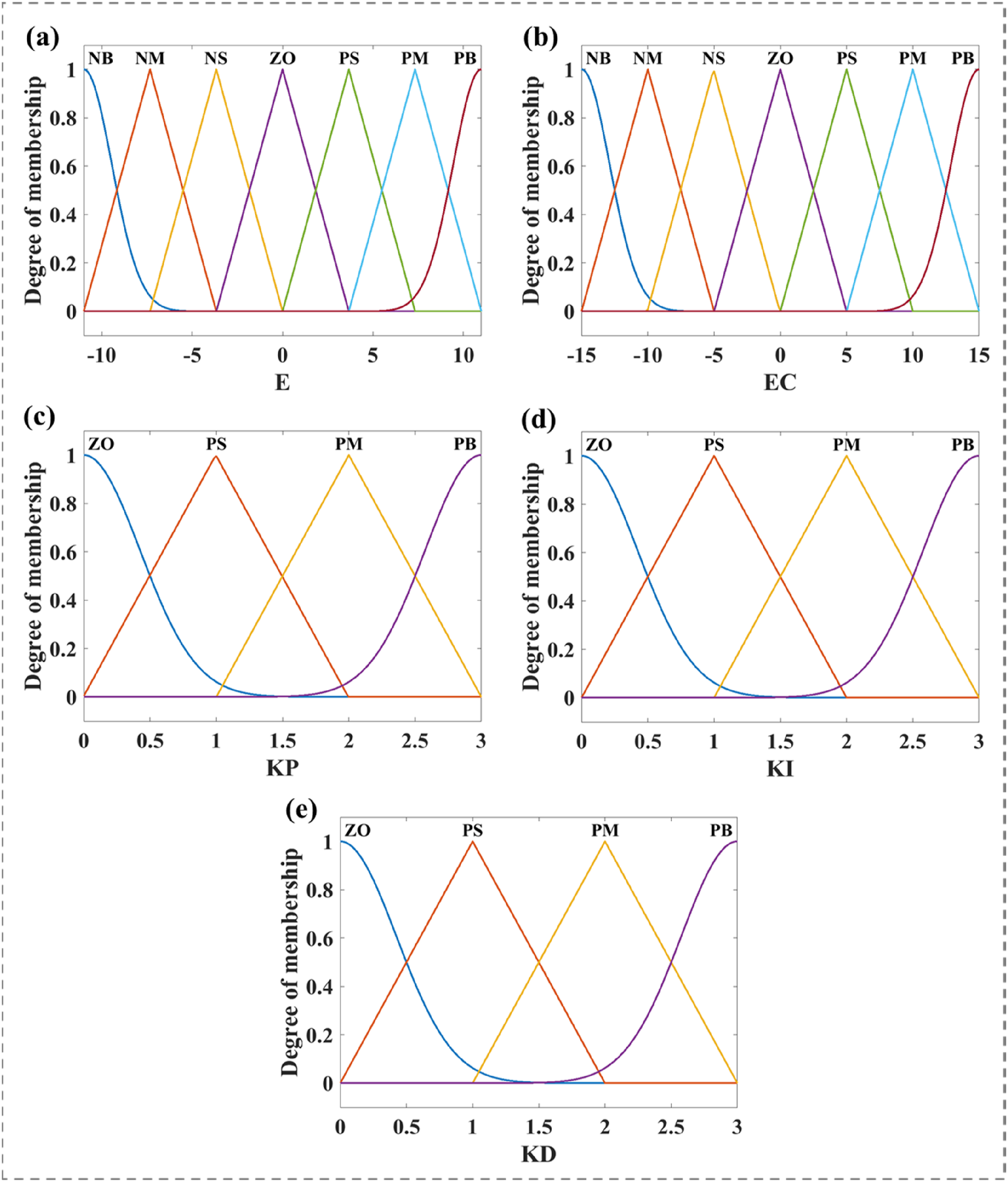
Fuzzy rules
The fundamental of fuzzy control is fuzzy inference based on fuzzy rules. These rules consist of a series of if-then rules. Based on expert knowledge and operator experience, we have gained a deep understanding of the roles of the three PID control parameters and mastered how to adjust them in different situations to achieve optimal control.
Specifically, the role of the proportionality coefficient KP is to speed up the system’s response and improve its regulation accuracy. The integral coefficient KI serves to eliminate the system’s steady-state error. The function of the differential coefficient KD is to enhance the system’s dynamic characteristics and stability by predicting changes in deviation in advance. Therefore, when the error
Fuzzy rules for


Defuzzification
The center of gravity method is used to convert a fuzzy conclusion into a precise value. It refers to the center of gravity of the area enclosed by the membership function curve and the abscissa. The formula of the center of gravity method is shown as
31
: The control surface of 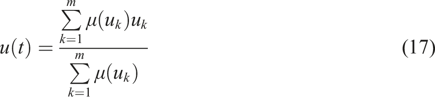

Results and discussions
Experimental validation of theoretical model
According to the test results of the monitored changes in various factors during the unwinding process of the four warp beams and the corresponding raw yarn tensile test results, we have comprehensively validated the established models. Specifically, the measured relevant data of tension, radius, speed, and air pressure measured during the warp beam unwinding process were fitted to Model 1 and Model 3. Additionally, the tension and elongation data of the warp yarn before breakage verified Model 2.
Testing data analysis
The test results of WB-1, WB-2, WB-3, and WB-4 under the PID tension control method during the actual unwinding process are illustrated in Figure 9. From Figure 9 (a1-2) (b1-2) (c1-2) and (d1-2), when the warp beams maintain at relatively constant speed during the unwinding process, the unwinding tensions of the four warp beams fluctuate around a constant value. At present, the warp beam unwinding tension control system utilizes PID closed-loop control. When the unwinding tension deviates from the set value, the braking torque of the warp beam is adjusted by modifying the air pressure to maintain stable tension. The sizing machine detects the yarn tension of multiple warp beams in the same sizing tank, and then collectively regulates all warp beams. However, differences in warping production, braking mechanisms, among other factors, contribute to variations among individual warp beams. Therefore, the uniform air pressure control for each warp beam leads to inaccurate control and periodic fluctuations in unwinding tension. Changes in warp beams unwinding tension, speed, air pressure and turns with radius under the PID tension control method during the actual unwinding process. (a) WB-1; (b) WB-2; (c) WB-3; (d) WB-4.
In Figure 9 (a3-4) (b3-4) (c3-4) and (d3-4), it is evident that as the unwinding radius decreases, the air pressure gradually decreases while the number of unwinding turns increases. According to equation (7), when the unwinding speed and braking torque are basically constant, the warp beam unwinding tension will gradually increase with the decrease of the unwinding radius until the yarn breaks. Therefore, the warp beam braking torque is reduced by decreasing the air pressure to ensure that the tension is always stabilized. In addition, from equation (10), when the unwinding speed is maintained at a certain level, the number of unwinding turns increases as the unwinding radius decreases.
In summary, during the uniform unwinding process, the unwinding radius of the warp beam gradually decreases and the number of unwinding turns gradually increases. The tension control system reduces the braking torque of the warp beam by constantly decreasing the air pressure to keep the constant tension.
Theoretical model 1 validation
In the actual production process, the warp beam related parameters 

Model 1 employed the nonlinear least squares fitting method through the lsqnonlin function in Matlab. This method is better suited for handling complex nonlinear relationships. The fitting quality was assessed using Validation of model 1. (a) WB-1; (b) WB-2; (c) WB-3; (d) WB-4. Fitting results of Model 1. Note: In the fitted equation, 

Theoretical model 2 validation
During the warp stretching process, 
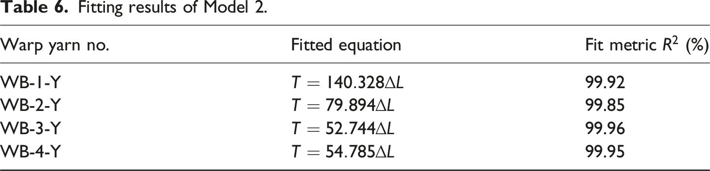
The linear fitting method in Origin software was used to fit Model 2, as it is simple and applicable to this model. The results of the tensile tests for WB-1-Y, WB-2-Y, WB-3-Y and WB-4-Y and the corresponding fitting results are presented in Figure 11 and Table 6. From Figure 11, the tension of the warp yarn gradually increases with increasing elongation during the stretching process. Table 6 shows that the Validation of model 2. (a) WB-1-Y; (b) WB-2-Y; (c) WB-3-Y; (d) WB-4-Y. Fitting results of Model 2.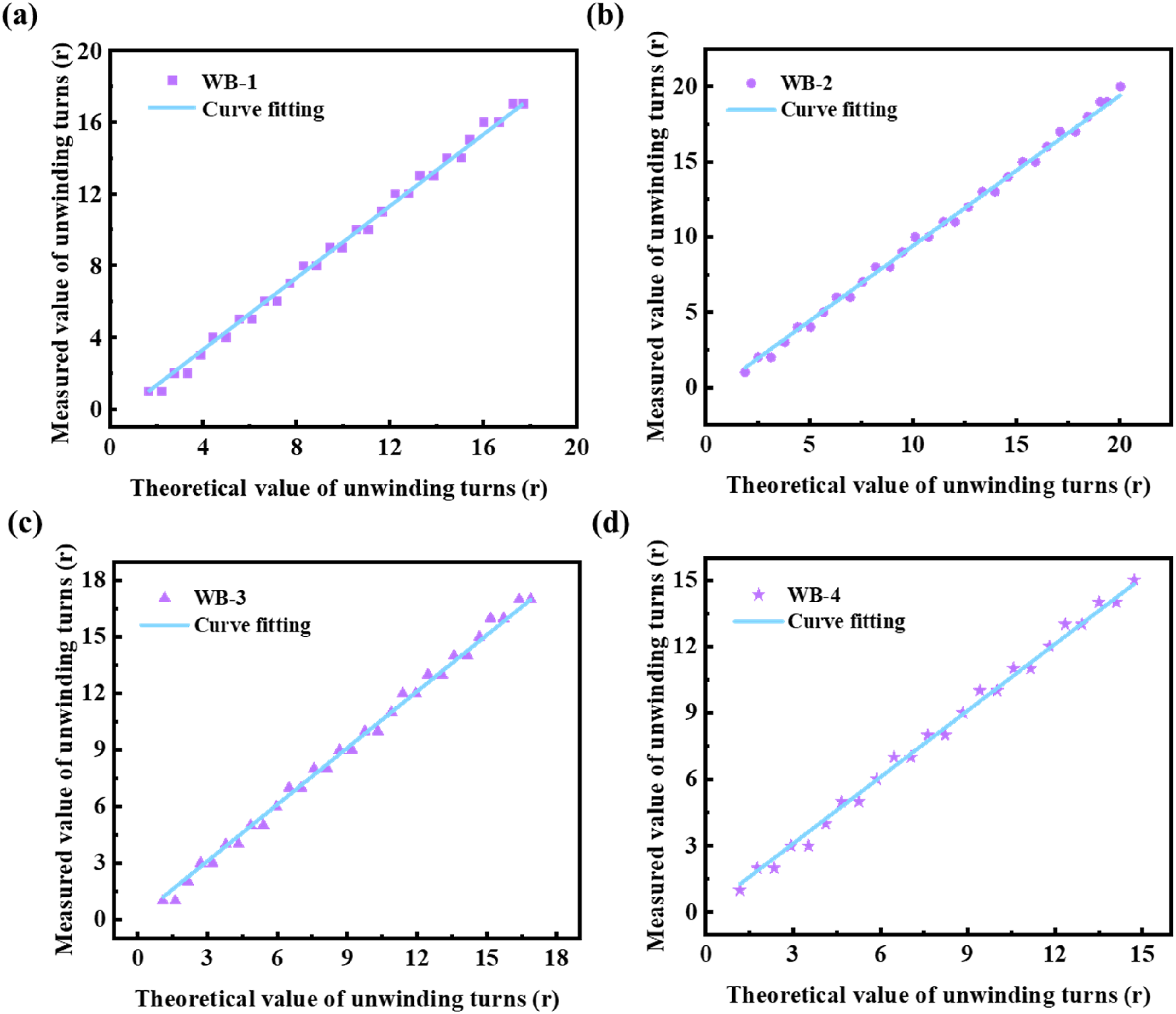
Theoretical model 3 validation
The equation (10) of Model 3 can be written as:
The theoretical number of turns( Validation of model 3. (a) WB-1; (b) WB-2; (c) WB-3; (d) WB-4. Fitting results of Model 3.

In summary, the experimental results demonstrated that the
At present, the conventional tension control method typically focuses on controlling tension by measuring tension. However, due to constraints in actual installation space, the individual detection of single warp beam unwinding tension has not been realized. It is worth noting that differences exist among warp beams. Consequently, to achieve uniform unwinding tension across the entire sheet yarns, it is fundamental to realize the stability in tension of single warp beam.
Based on actual production testing and the theoretical models outlined, we propose a new tension control approach. Specifically, Model 3 illustrates the relationship between the unwinding turns and unwinding speed. Moreover, there is also a relationship between the unwinding speed and the unwinding tension (Model 2), as well as the unwinding length (
Simulation verification of fuzzy PID tension control system
Parameters used in the simulation.

The unwinding radius and moment of inertia of the warp beam at different times.

Control effect under different reference tensions
To achieve constant unwinding tension with the unwinding length as the control target, simulations were conducted to investigate the tension response during the steady-state stage. When the reference unwinding tension
The simulation results of single warp beam unwinding tension control under the reference unwinding tension of 120 N and 200 N are depicted in Figures 13 and 14, respectively. From Figure 13(a) and 14(a), it can be seen that the input and output unwinding length are basically error-free after the proposed fuzzy adaptive PID method and traditional PID control method. Additionally, both methods achieve constant tension at different unwinding radius and reference tensions, as shown in Figures 13(b) and (c) and 14(b) and (c). However, it is observed that during constant-speed unwinding of large, medium, and small warp beams, the tension fluctuations were notably more pronounced when using the PID control method than the fuzzy adaptive PID method. The reason for this difference lies in the design of two control strategies. The fuzzy adaptive PID control continuously adjusts its control parameters in real-time based on the system’s changing conditions, whereas the traditional PID control operates with fixed control parameters during the entire unwinding process. Consequently, the fuzzy adaptive PID control demonstrates superior control effectiveness. The simulation results of single warp beam unwinding tension control under 120 N reference unwinding tension. (a) Unwinding length; (b) unwinding tension of large warp beam; (c) unwinding tension of medium warp beam; (d) unwinding tension of small warp beam. The simulation results of single warp beam unwinding tension control under 200 N reference unwinding tension. (a) Unwinding length; (b) unwinding tension of large warp beam; (c) unwinding tension of medium warp beam; (d) unwinding tension of small warp beam.

Control effect under different speed step interferences
Parameters of speed step interferences under 200 N reference unwinding tension.
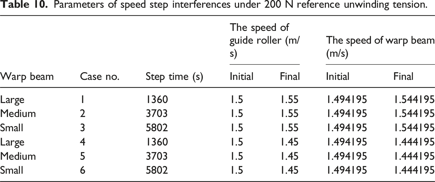
The simulation results are presented in Figures 15 and 16. From Figure 15(a)–(c) and 15(d)–(f), when the speed of the guide roller suddenly increases from 1.5 to 1.55 m/s or decreases to 1.45 m/s, these changes in speed lead to unwinding tension fluctuations. However, as the unwinding radius decreases, the effect of the step disturbance becomes smaller. Both control methods can adjust to restore the tension to the desired state, but the PID control results in greater tension fluctuations. Control effect of speed step interferences in fuzzy PID method and the traditional PID method under 200 N reference unwinding tension. (a) Case 1; (b) Case 2; (c) Case 3; (d) Case 4; (e) Case 5; (f) Case 6. Tension error under different speed step interferences in case 1-6.

Figure 16 shows the specific tension errors. It is evident that the unwinding tension overshoot and downshoot of the fuzzy PID control for the large, middle and small warp beam are smaller than those of the PID control. After applying the fuzzy PID control method, the tension fluctuation range of Case 1-6 is significantly reduced by 64.49%, 71.40%, 72.25%, 65.92%, 70.14% and 72.59%, respectively. Thus, the proposed fuzzy PID control method is superior to traditional PID control, demonstrating better anti-interference ability.
Control effect under different noise disturbances
Parameters of different noise signals under 200 N reference unwinding tension.
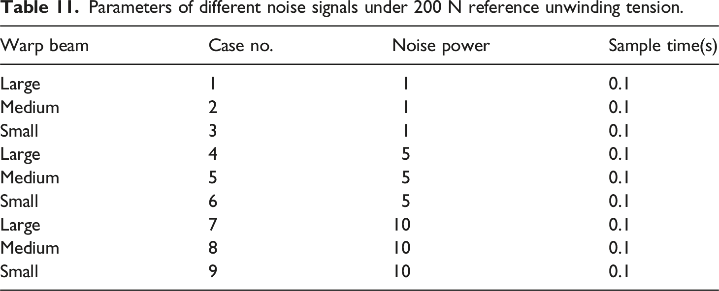
The control effects of the fuzzy PID control method and the traditional PID control method under various noise signal disturbances are illustrated in Figure 17. Throughout the entire unwinding process, tension exhibits varying magnitudes of fluctuation above and below a constant reference value after control by both methods in response to different noise disturbances. Obviously, the fuzzy PID control method further reduces the fluctuation range compared to the PID control method. Control effect of different noise signals in the fuzzy PID method and the traditional PID method under 200 N reference unwinding tension. (a) Case 1; (b) Case 2; (c) Case 3; (d) Case 4; (e) Case 5; (f) Case 6; (g) Case 7; (h) Case 8; (i) Case 9.
Moreover, it is observed that the magnitude of tension fluctuation increases with the intensity of noise. In contrast to Figure 17(a)–(c), (d)–(f) or (g)–(i), as the unwinding radius of the warp beam decreases, the fluctuations in tension under the same noise conditions also diminish. The specific tension error values for Cases 1-9 are detailed in Figure 18. Compared to traditional PID control, the fuzzy PID control method reduces the tension fluctuation range by 29.41%, 29.33%, 24.89%, 30.13%, 28.07%, 24.29%, 31.02%, 27.81%, and 23.66% for Cases 1-9, respectively. Hence, the proposed method has better anti-noise interference capability. Tension error under different noise disturbances in case 1-9.
In summary, the fuzzy PID control can achieve constant tension control in the entire unwinding process of single warp beam by controlling the unwinding length. When there are speed step interferences and noise disturbances, the fuzzy PID control has better control effects than traditional PID. Therefore, the proposed single warp beam unwinding tension control method exhibits stability, robustness, and anti-interference ability.
Cost-benefit analysis of the system
In this paper, constant unwinding tension control for single warp beam is successfully realized by measuring the unwinding turns and applying the fuzzy PID control method. The proposed system does not require any modification of the warp beam frame of the sizing machine. Only unwinding turns sensor, controller, proportional valve and other auxiliary components need to be purchased. The initial investment for single warp beam is estimated to be a maximum of US$198. In contrast, the traditional tension control mode of measuring tension requires modification of the warp beam frame, resulting in significantly higher costs. More importantly, the cost of a tension sensor (about US$150) is much higher than that of an unwinding turns sensor (about US$12). Additionally, components such as the controller and proportional valve also need to be purchased. Therefore, the proposed system is low-cost and easy to implement.
Moreover, this system effectively reduces tension fluctuation during the entire unwinding process by precisely controlling the unwinding tension of single warp beam. The quality and efficiency of the sizing process is significantly improved. If this system is applied to the entire warp beam frame, it will ensure consistent unwinding tension across multiple warp beams, reducing residual yarn at the end of the unwinding process and conserving resources. 27 Furthermore, the improvement of sizing quality contributes to enhanced weaving efficiency and ensures the uniformity of the fabric surface during the weaving process. 33 It enhances product quality and increases company revenue. The specific costs and revenues will depend on the type of yarn used in production. In the future, we will expedite the practical application of this system and continue to monitor the specific cost-benefit data.
Conclusions and future research
In this study, experimental data on tension, speed, radius, turns, and air pressure during the warp beam unwinding process are successfully obtained through the construction of detection devices to verify the established coupling models between these factors. Subsequently, a novel fuzzy adaptive PID control system for single warp beam unwinding tension is designed based on these models, and its performance is evaluated through simulations. The main conclusions are summarized as follows: (1) The tension coupling models are established and verified. Experimental data of the four measured warp beams are fitted to verify the established coupled model relationships between unwinding tension, speed, radius, turns and air pressure. Specifically, the fit metrics (2) Based on the above models, a novel fuzzy adaptive PID control system for single warp beam unwinding tension is proposed with the unwinding length as the control target. This system uses the unwinding turns detection device to monitor real-time changes in the warp beam, thereby maintaining constant tension. It offers a new control mode of measuring turns to control tension and differs from the traditional method of measuring tension to control tension. (3) The proposed system demonstrates stability and robustness in controlling the unwinding tension of single warp beam through simulation analysis. It can maintain constant tension under different reference tensions and unwinding radius. Compared to traditional PID control, the fuzzy adaptive PID control method significantly reduces tension fluctuation, with reductions of 64.49% under different speed step disturbances and 23.66% under noise disturbances.
Therefore, the proposed tension coupling models and novel tension control method have been proven effective. Based on these findings, future research should prioritize further experimental validation in real-world conditions and explore new control methods (such as predictive control) to optimize the system. Additionally, achieving consistent tension for multiple warp beams in sizing machines is essential. It is also advisable to broaden the application of this technology across the textile industry to improve production efficiency and product quality.
Footnotes
Declaration of conflicting interests
The author(s) declared no potential conflicts of interest with respect to the research, authorship, and/or publication of this article.
Funding
The author(s) disclosed receipt of the following financial support for the research, authorship, and/or publication of this article: This work was supported by the Natural Science Foundation of Jiangsu Province (grant no. BK20221061) and the Postgraduate Research & Practice Innovation Program of Jiangsu Province (grant no. KYCX24_2552).