
Abstract
This study focuses on the development and assessment of advanced construction materials, such as a unique slab design, longitudinal void configurations, and profiled steel deck. The aim was to improve the efficiency of constructing reinforced composite buildings and enhance their visual attractiveness. In order to evaluate the strength and efficiency of these new developments, we carried out a thorough examination utilizing ANSYS Workbench. Our study specifically concentrated on analyzing the failure characteristics of nine slabs that were supported in a simple manner. The study conducted a thorough comparison of different factors, including the shapes of the voids and profiled steel decks, the presence of embossments and nodes, and the type of concrete utilized (conventional and light-weight using Expanded Polystyrene (EPS) and Polypropylene fibers). Our results from a thorough flexural analysis showed that slabs containing oval-shaped voids demonstrated the best performance in terms of structural stability and efficiency. In addition, the profiled steel deck, which includes embossments and dimples, demonstrated exceptional performance as a result of the improved mechanical connection, which was further demonstrated in the LightcompvoidSteelslab. The results indicate that incorporating oval voids and embossed steel sheets into slab construction has the potential to greatly enhance the mechanical characteristics and construction efficiency of composite buildings. This study provides valuable knowledge on the design and utilization of sophisticated composite materials in the construction sector, which could potentially result in more environmentally friendly and economically efficient building methods.
Keywords
Introduction
In the construction sector, over the decades there has been a notable rise in interest in sustainable composites as a key strategy for protecting the environment. This shift has spurred investigations into substitutes for conventional reinforced concrete slabs.
Composite slabs consisting of steel decks with a topping have emerged as a popular alternative because of their effectiveness, cost efficiency, fire resistance and ease of use.1,2 Significant studies have been conducted on these slabs, examining differences in steel sheet thickness, slenderness, span, geometry, and profile.3–8 Lightweight concrete was also investigated and has demonstrated better composite action and ductile behavior in composite slabs, though it has been linked to reduced shear resistance and load-carrying capacity.9,10 Several techniques, including end anchoring, embossments, and natural chemical bonding, have been used to improve the composite action between steel and concrete.11–16 By contrasting materials like self-consolidating concrete (SCC) and engineered cementitious composite (ECC), recent research has examined a variety of structural characteristics of composite slabs. 17 It has been stated that shear failure resulting from slippage is the most common failure mode in these slabs,18,19 and performance and ultimate load capacity are greatly influenced by steel sheet profile, embossments, shear studs, and reinforcing. When compared to conventional concrete composite slabs, alternative materials such as crumb rubber concrete have demonstrated potential in increasing ductility and failure load.20–26 In bridge building, the sustainability of composite constructions has also been assessed by contrasting steel and concrete options. 27
The voided slab is another lightweight option that has been researched since it significantly lowers self-weight when compared to traditional solid slabs. The weight reduction is attributed to the presence of longitudinal voids of various shapes. But along with this weight reduction come increased deflection, stiffness, cracking loading, and decreased load-carrying capacity.28–30 To mitigate these disadvantages, researchers have examined at the use of concrete topping31–35 and fiber-reinforced polymers (FRP).36,37 Voided slabs present unique challenges, such as reduced fire resistance,38,39 but offer thermal benefits due to the presence of voids.40,41 Voided slab research has explored various void shapes and materials, including steel pipes, PVC pipes, and ultra-high-performance strain-hardening cementitious composite (UHP-SHCC) tubes.42–48 The addition of concrete topping and the use of polypropylene fiber-reinforced concrete (PFRC) have demonstrated improvements in voided slab performance.34,49 Novel concepts such as the Tubedeck slab, featuring circular paper tubes, have shown high stiffness and ductility.50,51
Moreover, in order to address rising construction costs, declining natural resources, and rising pollution, the increased emphasis on sustainable construction has made the use of alternative methods and materials necessary. Global CO2 emissions have been found to be significantly influenced by the cement industry in particular. In 2018, the world’s production of cement was about 4.1 billion tons, where only 1 kg of cement production can produce 981 kg of CO2.52–55 Attempts have been made to replace cement with other waste materials, such as ground granulated blast furnace slag, 56 marble and brick powders, 57 rubber, 58 plastic, 59 and organic waste,60–62 as a sustainable solution for the problem of a lack of natural sources and a beneficial method for reducing the quantity of waste material on the planet.63,64 One pioneering development includes incorporating expanded polystyrene (EPS) beads as ultra-light weight aggregates in composites due to their minimal weight, low water absorption rate and impressive thermal and sound insulation features. By using fewer endangered resources and lowering harmful emissions from production processes, these techniques help create more ecologically friendly buildings. The use of EPS beads as aggregates has introduced new possibilities in concrete design, offering high energy absorption capacity and impact resistance.65,66 However, better mechanical properties and density control could be achieved by using plastic fiber, as stated in Ref. 67.
Fiber-reinforced and textile-reinforced concrete are advanced materials that further improve the mechanical properties of conventional concrete. They benefit construction applications in many ways; they create lightweight, durable structures with better load-carrying capabilities and design freedom. The following sections illustrate the advantages of FRC. In FRC, the cracking and environmental degradation resistance improve toughness, as the embedded fibers allow for better distribution of stress. 68 Besides, the addition of fibers increases the load-carrying capacity of concrete considerably, and hence, FRC is used in applications with high demands, such as bridges and high-rise buildings. 69 On the other hand, TRC has several unique advantages. Complex geometries and free-form constructions that are impossible to achieve with conventional concrete are made possible by design flexibility. 70 Furthermore, the TRC material has a good strength-to-weight ratio, which is advantageous for applications where weight is a concern. Additionally, TRC’s textile reinforcements resist corrosion, extending the life of structures, particularly in severe situations. 69 To fully realize the performance potential of both FRC and TRC, more research is necessary to improve the bond between the reinforcements and the concrete matrix. 68
Fiber-reinforced and textile-reinforced concretes (FRC and TRC) are increasingly recognized for their ability to improve the mechanical performance of cement-based composites, particularly in terms of flexural behavior and overall durability.71–74 Naser et al 75 highlighted the advantages of FRP systems for flexural, shear, and torsional strengthening. They stated that studies showed significant increases in stiffness and strength of strengthened beams which is influenced by carbon fiber stiffness, direction, and number of plies. However, Enhancing FRP material properties is essential for broader civil applications. Ghorbani et al. 76 explored the flexural response of self-consolidating mortars (SCM) reinforced with warp-knitted spacer fabrics (WKSF). The analysis demonstrates that the incorporation of WKSF reinforcement enhances the flexural strength, stiffness and toughness of SCMs to a greater extent, especially with larger mesh sizes and thicker fabrics. This is attributed to the ability of the spacer fabrics in reducing delamination and facilitating matrix penetration, thereby creating a strong matrix-fabric bond. Moreover, de la Fuente et al. 77 assessed the sustainability of the column-supported reinforced concrete (RC) slabs in terms of whether fiber-reinforced concrete (FRC) can be used as a substitution material. Results showed that construction cost and time were considerably less in the steel-fiber-reinforced self-compacting concrete alternative than the other options, although it had higher steel usage and environmental impact, and was notably less risky in terms of occupational safety. Attia et al. 78 stated that basalt fiber-reinforced concrete slabs and basalt fiber-reinforced polymer bars showed substantial gains in cracking loads and load-carrying capacity. Moreover, increased fiber volume fraction led to more cracks and reduced crack spacing.
In light of the details mentioned above, the objective of this manuscript is to present a detailed study on the effect of various void shapes as well as the different geometry of the steel sheet on the behavior of voided composite slab, which is an unprecedented type of slab that is expected to combine the advantages of both voided slab and composite slab. This novel type of slab could be considered environmentally friendly due to the reduction of the amount of cement needed and the use of EPS and plastic fiber, which produce sustainable structures for people. This study is also a novel approach to merging the two types of slabs, which overcome both flaws and get the maximum benefit from their best properties.
Finite element modelling
Specimen details
Nine slabs of the same dimensions (3 × 1.5 × 0.15) m, categorized in four groups were modelled and analyzed. The experimental study is divided into four groups. Group A includes a solid slab, S1, which serves as the reference slab, as illustrated in Figure 1. Group B comprises three voided slabs with different void shapes: rectangular (VCR), oval (VCO), and round-box (VCB), with cross sections and specimen details shown in Figure 2. Group C features three composite slabs, each with varying geometry and reinforcement configurations on top of the slab (CD, CE, CN), with specific details described in Table 1 and illustrated in Figure 3. Lastly, Group D includes two voided composite slabs, formed by combining the voided slab from Group B with the composite slab from Group C that demonstrated the best performance in the analysis. This group includes VCC, which uses conventional concrete, and LVCC, which incorporates lightweight concrete with EPS and polypropylene plastic fibers. Table 1 provides the abbreviations and descriptions of these slabs. Group A: Solid Slab S1 (All dimension is in mm). Group B voided slabs: (a) VCS, (b) VCO, (c) VCB (All dimensions are in mm). Details of the specimens. Group C Composite Slabs: (a) CD, (b) CE, (c) CN (All dimensions are in mm).
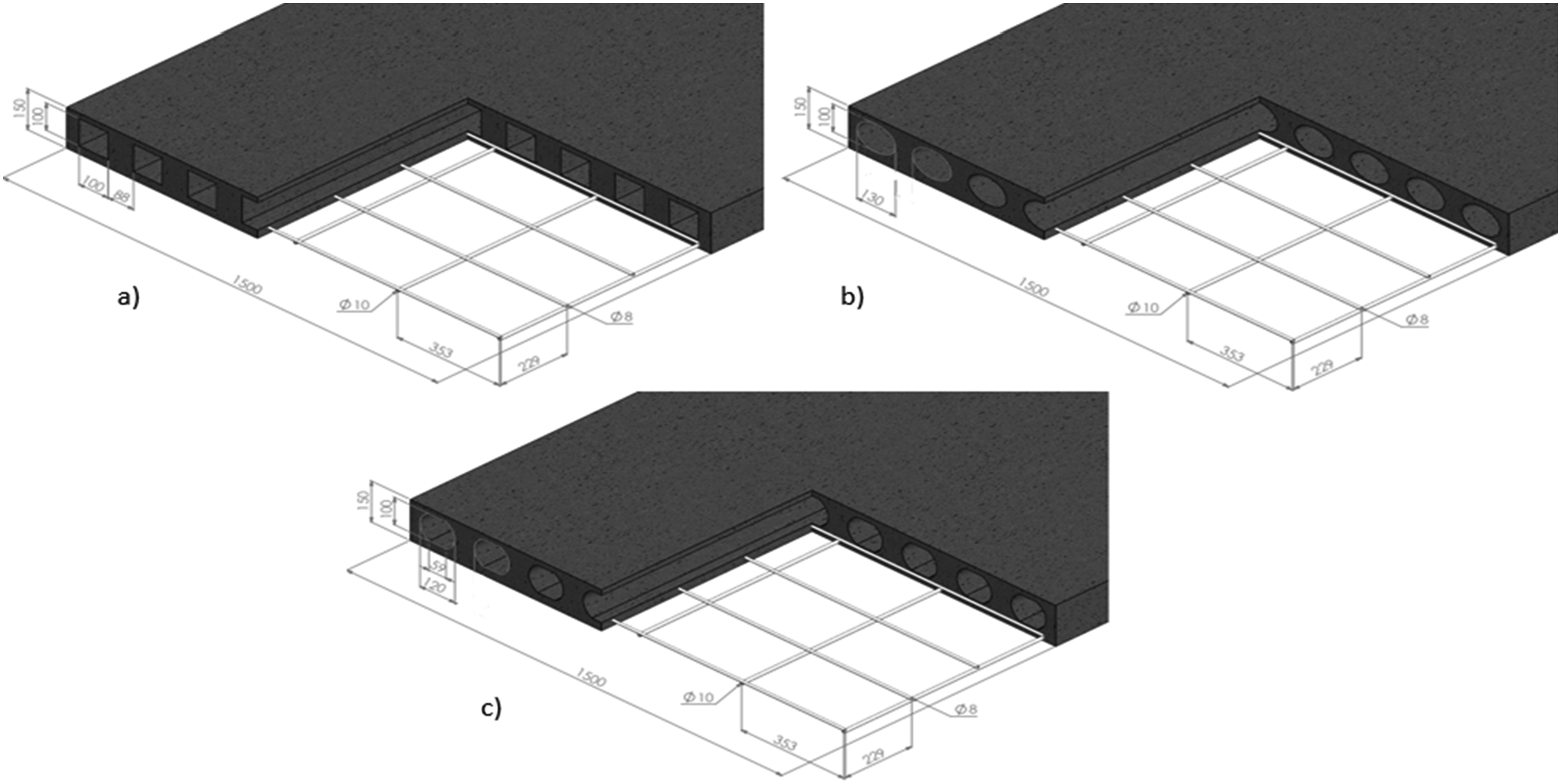

The cross section and geometry of voided composite slabs were chosen based on the analysis results of groups B and C, from which the slabs with the superior behavior were chosen to model voided composite slabs in order to eliminate the shape factor and concentrate basically on the effect of the type of concrete on the performance of the slab. In order to investigate the flexural behavior and load-carrying capacity of voided composite slabs, ANSYS Workbench software was used, which is perfectly capable of performing detailed analysis with traditional FEA methods in a fraction of time. SOLIDWORKS was used to model the steel sheets before they were imported to ANSYS.
Materials, modelling, and properties
Properties of materials.
aNWC and LWC stands for normal weight concrete and light weight concrete, respectively.
Figure 4 illustrates the modelling of solid slab and its reinforcement in ANSYS, while Figure 5 clarifies the modelling of voided slabs. The main criteria adopted during the design process was to fix the area of the voids (10,000 mm2 for each void), while the shape of the core is the only variant. This approach was adopted to acquire a clear understanding of the possible effects of the different voids’ shapes on the flexural behavior of the slabs. Steel sheets were designed based on Eurocode 4
80
and with reference to20,29,81. The mechanical bond between the concrete and steel sheets, which is achieved by introducing embossments and deformation to the steel decks, improves the composite action, which in turn increases the ultimate load and decreases the deformation. Figure 6 shows the 3D modeling of the steel sheets in SOLIDWORKS. For further reduction of self-weight, light-weight concrete using EPS and waste plastic fiber was adopted to examine the performance of the voided composite slab. Modelling of S1, (a) Cross Section and (b) Reinforcement. Modelling of Group B: (a) VCS, (b) VCO, and (c) VCB. 3D modelling of the steel sheets (a) CD, (b) CE, (c) CN.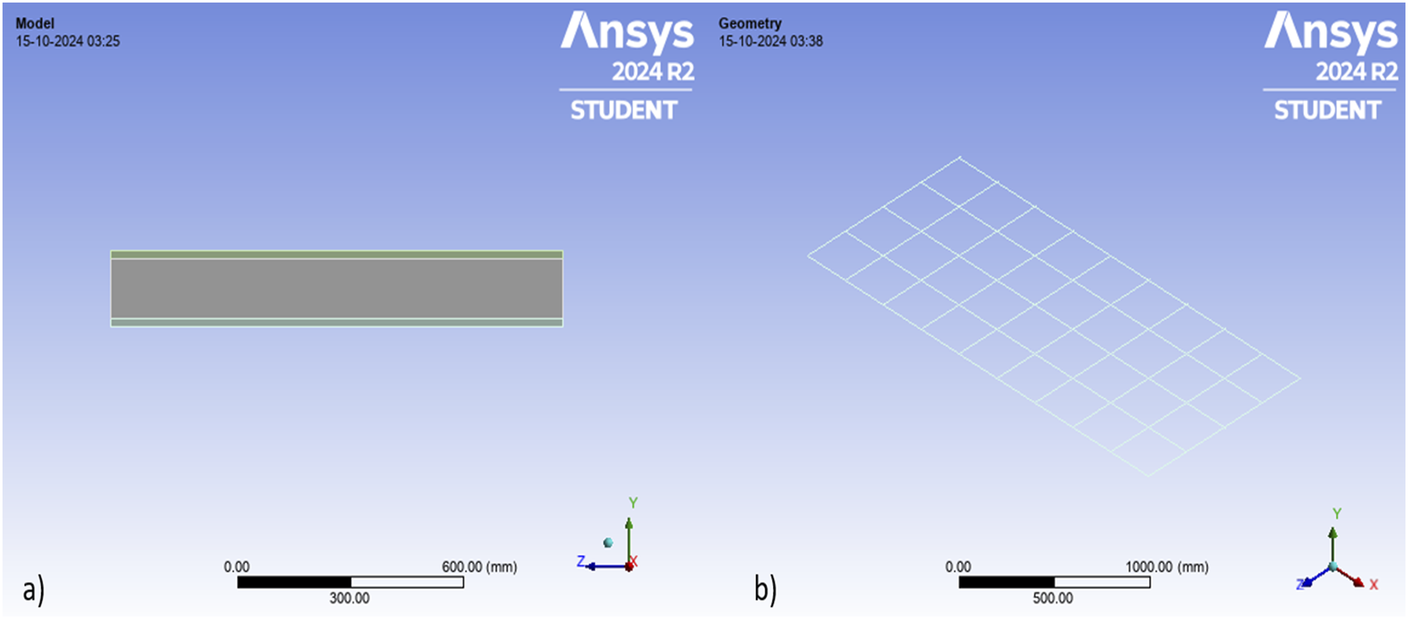


Three profiled steel sheets were admitted for this study: Steel Sheet 1 has embossments on the top and web of the flange as well as two dimples on the body of the sheet (Figure 6(a)); Steel Sheet 2 has embossments only on the upper part of the flange (Figure 6(b)); and Steel Sheet 3 has embossments on the sides of the flange, a U-notch on top of it, and one dimple on the body of the steel sheet (Figure 6(c)). The steel sheets were modeled using SOLIDWORKS software, which enabled the detailed production of the embossments and deformations of the steel sheets. The density of concrete was reduced from 2300 kg/m3 to 1637 kg/m3, based on the best results obtained from Medher et al,
82
while the modulus of elasticity was calculated based on the following equation (1):
Moreover, the fibers are cut from waste plastic into the dimensions of 40 mm length, 3 mm width and 0.8 mm thickness. The density of fibers is 1400 Kg/m3, the tensile strength is 220 MPa and the modulus of elasticity is 3.2 GPa. 82
Type and geometry of structural member
Figure 7 shows the details of the elements: solid 65, link 180, and shell 93. As concrete is stronger in compression than in tension, a solid concrete slab exhibits an initial linear elastic response, followed by a plastic response characterized by strain softening after the peak stress is reached. On one hand, tension in concrete results in formation of cracks perpendicular to the principal stress direction. Therefore, SOLID65 was chosen to simulate the non-linear behavior of concrete in Ansys. SOLID65 is an element that has eight nodes and three degrees of freedom and has the capability of cracking and crushing. The member behaves as a linear elastic material until the stress reaches either the maximum compressive strength or tensile strength.67,83,84 The principal stress outreaches the strength at an integration point where a plane of weakness in the normal direction of the stress is introduced to represent cracking in the member. βt and βc are two shear transfer coefficients that determine the amount of shear transferred through open and closed cracks, respectively. The values of the coefficients range from 0, which represents no shear transfer at the crack section, to 1, which represents full shear transfer. Illustration of the structural members: (a) Solid65, (b) Shell93 and (c) Link180.
However, in this investigation, βt is assumed to be 0.3 and βc is assumed to be 0.8, as these high values proved to prevent the convergence problem. 12 Top reinforcement was used to resist the shrinkage and temperature effects. Reinforcing bars were modeled using the LINK180 element, which is a uniaxial tension compression element that has the properties of swelling, creep, and plastic deformation. Simulating the elastic and isotropic behavior of the steel sheets in ANSYS was done using the SHELL93 element, which is defined by eight nodes and six degrees of freedom at each node. This element was chosen as it has the properties of plasticity, large strain capacity, large deflection, and stress stiffening.
Boundaries, mesh, and loading
The slab was subjected to a flexural test, as elucidated in Figure 8, and it is simply supported. A hinged support was provided on one side and a roller support on the other side. Non-linear static analysis was adopted with two loading points (P/2) for each one of them. The loads were applied on two steel plates, to simulate the real experimental test, with the dimensions of 50 × 100 mm. The plates were modelled to assure a proper distribution of loads, and to avoid the problem of local load concentration, as the program applies the load on a line of nodes, unlike the real experimental test. Flexural test of the specimen (All dimension is in mm).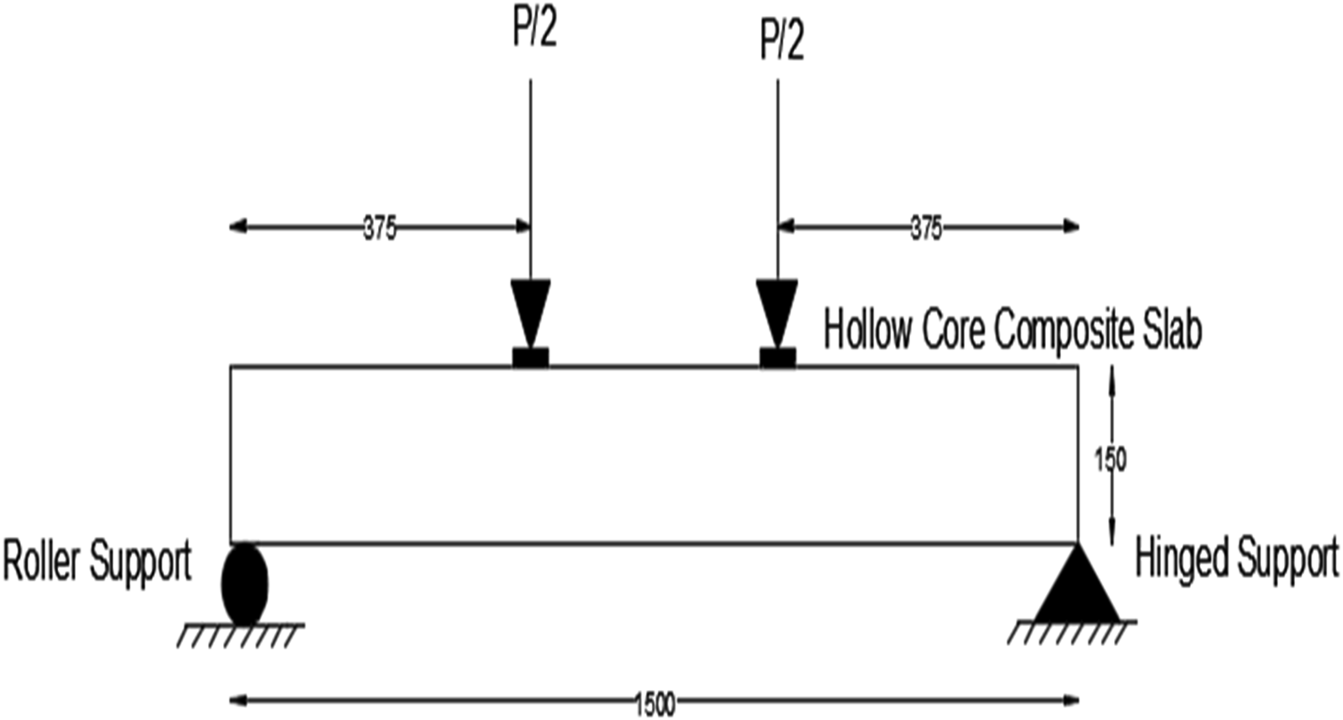
Sensitivity test it is found that 50 mm and 100 mm meshes’ results did not show a noticeable variance, and 50 mm mesh was chosen as shown in Figure 9, which illustrates the sample meshing of the oval voided slab when 50 kN was applied in the meshing of S1. Sample of meshing: (a) solid slab, (b) hollow core slab.
However, the deformation of the steel plate was not taken into consideration. The load was applied at L/4 = 375 mm from each side. A displacement-controlled loading is adopted, and its magnitude is increased gradually until the steel reinforcement has reached its yield point. Additionally, the load step started with the optimum value, and then we let ANSYS change it automatically based on the number of non-linear iterations performed at each load step. The load was applied throughout the steel reinforcement in the case of the voided slab and the steel sheet in the composite slab, and the voided composite slab has reached its yield strain, which was considered the end point of the test. In order to determine the optimal mesh size, a sensitivity test has been conducted, and a 50 mm mesh size was adopted based on the trials, as finer mesh caused the problem of convergence and was time-consuming, while larger mesh yielded inaccurate results with a wide range of variance (Figure 9).
Results and discussion
Voided slab
Ultimate load carrying capacity versus deflection
Results of the slabs behavior analysis.


Deflection of S1 and VCO.
Non-linear static analysis of the oval voided slab VCO has yielded the highest load-carrying capacity of 350 kN, while the square-voided slab has yielded the least load-carrying capacity of 320 kN. Voided slab with round-box cores (VCB) has developed an ultimate load of 325 kN. Additionally, the maximum deflection was observed at the midspan, where S1 showed a deflection of 10.1 mm, while the deflections of VCS, VCO, and VCB were 6.1, 7.9, and 6.8 mm, respectively. Figure 11 shows the load-versus-deflection relationship among the voided slabs. Comparing the results among the voided slab and the solid slab S1, which developed a load-carrying capacity of a load-carrying capacity of 460 kN, it can be perceived that the ultimate load has dropped to almost 29% in VCB, 24% in VCS, and 30.4% in VCO, respectively. This dramatic decrease can be attributed to the presence of voids, as the ratio of the voids to the total cross-sectional area is almost υ = 62%, which in turn reduces the compression area of the concrete. Load versus deflection of solid and voided slabs.
On one hand, shear strength is influenced by the cross section of the slab, which is higher in a solid slab than in a voided slab due to the existence of cores. However, the presence of voids has the major advantage of reducing the self-weight of the slab, as clarified in Table 3. Based on the analysis results, it can be concluded that the shape factor is significant in the determination of the load-carrying capacity as all the voided slabs have the same cross-sectional area (the main criteria of the analysis was to consider the cross-sectional area of the voids constant while their shapes were the variables). But those have different load-carrying capacities. Sharp corners of voids, such as square voids, cause stress concentration, which results in crack formation and reduces the stiffness and load-carrying capacity of the slab, which explains the highest ultimate load of VCO. As the weight of the concrete reduced by 576 kg, the CO2 emitted has also reduced by 565.065 kg, which is beneficial from an environmental point of view. Based on that, the reduction in material needed has both economic and environmental advantages, as the air pollution is reduced, the natural sources are preserved, and the cost of construction has decreased. This can directly contribute to the sustainability of the structural system.
Modes of failure
The voided slab has shown the same flexural failure mode as the solid slab, with minor differences regarding the shear crack. Figure 12 shows the crack pattern of S1 and VCO. Failure patterns; (a) S1, (b) VCO.
One of the most important features of ANSYS is that, by adding an APDL command, it gives the possibility of presenting the cracking and crushing of the slabs. In a voided slab, flexure cracks started appearing in the middle third of the slab and then propagated, while some shear cracks were developed because of the void, especially at the corners of the structural member, which could be explained by the stress concentration on the sharp angles in the case of shapes with an angle, i.e., VCS. However, the crushing of concrete occurs under the loading point and above the supporting point, which is almost the same as in the solid slab. The failure mode was flexure failure in all the slabs.
Ductility
The ductility of a slab is its capability to sustain large inelastic deformation without extreme deterioration of strength. Deformation ductility is expressed in terms of the maximum deflection to the yield deflection in the midspan of the slab (u/y). The range of deformation ductility is from 1, which refers to elastic behavior, up to 6, which refers to perfectly ductile. Concrete is considered a brittle material. Based on this fact, the brittle failure of solid slabs and voided slabs can be explained.
Composite slab
Ultimate load carrying capacity versus deflection
Steel sheet in composite slabs acts as tension reinforcement since it has a higher ratio of strength to weight, while the top reinforcement resists temperature and shrinkage effects. The presence of embossment and deformation of the steel deck causes a considerable increase in the ultimate load when compared to the plain steel sheet, which is attributed to the friction action and the mechanical bond that their presence causes. The ultimate load-carrying capacity of CD exceeded the load-carrying capacity of solid slab S1, and its deflection was also less; they were equal to 740 kN and 6.9 mm, respectively, with an increase of 38% when compared to S1. The CE has the least load-carrying capacity (560 kN), and its deflection was 5.23 mm, a decrease of 17.8% when compared to S1. The ultimate load and deflection of CN were 600 kN and 5.05 mm, respectively, a reduction of 23.3% compared to that of S1. This result comes in accordance with the proven fact that the presence of steel sheet increases the load-carrying capacity of the slab based on the presence and distribution of the embossments. The shape and dimension of the embossment are crucial factors in determining the ultimate load. In the case of CD, the embossment is located on the rib and the web of both the flange and the steel sheet (inwards to concrete), while in CN, the rib has a U notch (outwards from concrete) on top of the flange, the embossment would be on its sides, and two dimples would be on the body of the steel sheet. The direction of the embossment is important in terms of the bond connection between the concrete and the steel, as the interaction forces are always located at the ends of the embossment.
20
The detachment reaction of the outward embossment is considered higher than the inward notch since the concrete tends to remain straight while the steel sheet bends. Therefore, higher forces are required to bend the sheet to cause horizontal slippage. Figure 13 illustrates the deformation of CD, and Figure 14 shows the load-versus-deflection relationship of composite slabs. Deflection of CD. Load versus deflection in the composite slab.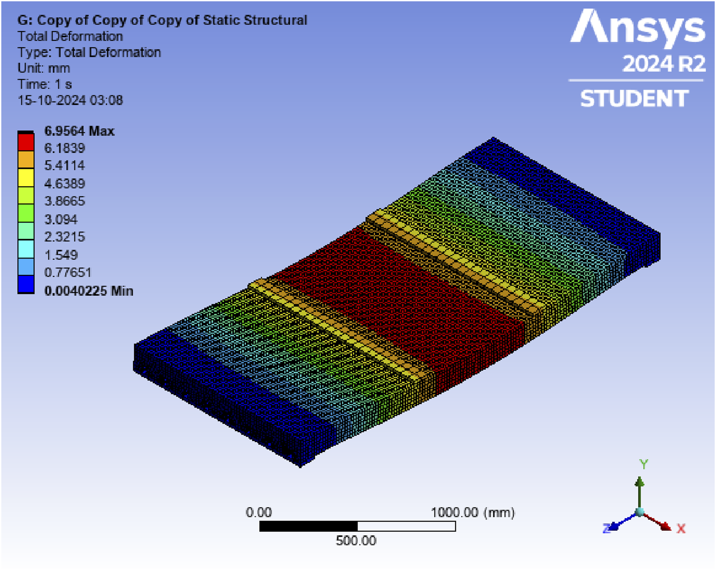

Additionally, the width and slop of the embossment might be considered carefully, as they are important parameters in slippage resistance. Increasing the width of the embossment increases the moment of inertia; hence, the interaction forces developed during slip increase. And increasing the slip resistance requires the embossment to be steeper.
Modes of failure
Figure 15 shows the failure pattern in the composite slabs. End slippage is the common failure of composite slabs, where the longitudinal slip is transformed by the wedge effect of embossment into various actions between the steel and the concrete, such as steel sheet bending. The ability of embossment to develop the internal forces components, which are the contact forces from any section to the nearest support and equal to the compression of concrete in that section, would determine the longitudinal shear resistance of the entire slab. Failure pattern of composite slabs: (a) CD, (b) CE, (c) CN.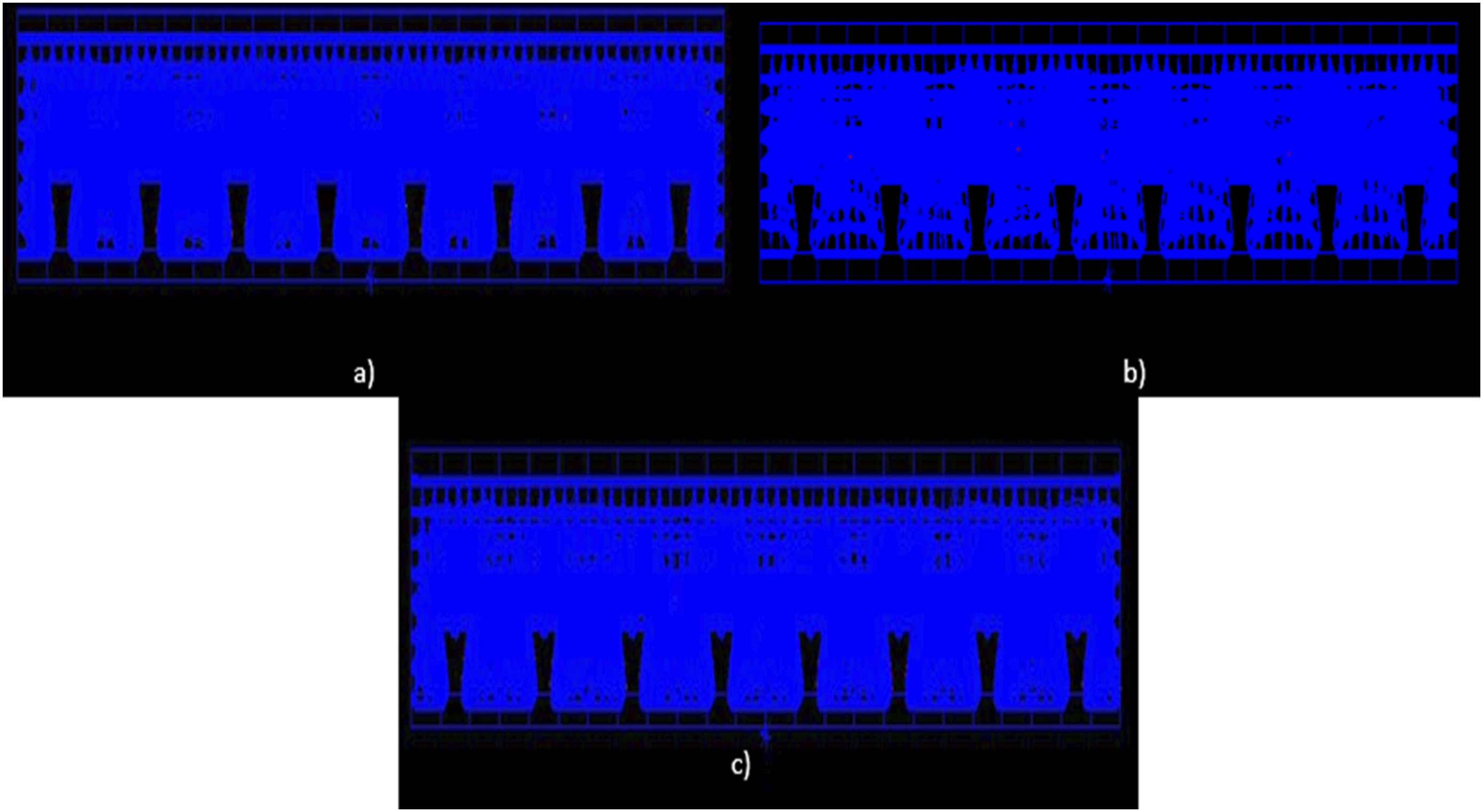
However, the longitudinal shear acts in the opposite sense to the slip. 54 It can be clearly understood that the degradation of concrete in CE is greater than that of CD and CN, which is due to the absence of flange-side embossment and sheet deformation. This could cause much slippage because of the less bonding action between the steel sheet and the concrete.
Ductility
Composite slabs are known for their ductile behavior, which has reached its peak for CD with a deformation ductility ratio of 4.3, while it was 3.02 and 3.18 for CE and CN, respectively. This can be attributed to the fact that the indentation and the embossment develop the composite action of the material, which makes the slab experience more deflection until they reach their plastic stress limit.
Voided composite slab
Ultimate load carrying capacity vs deflection
Voided composite slab with normal weight concrete (VCC)
Based on the analysis of groups B and C, VCO and CD have exhibited the best results and were merged to perform the voided composite slab VCC, which is expected to attain the advantages of both slabs, i.e., the self-weight of VCO is less than that of CD, and it is economical as no formwork is needed (steel sheets act as permanent formwork) and less material is needed due to the existence of the cores, which adds the important criteria of sustainability to the list of benefits of this new type of slab. The cross section of VCC is shown in Figure 16, while the 3D view that was modeled on SolidWorks is shown in Figure 17. Cross section of VCC. 3D view of the VCC.

Based on the analysis shown in Figure 18, which was aimed at exploring the possible behavior of this new type of slab, it has been found that the ultimate load of the slab was 705 kN, which exceeds the load-carrying capacity of VCO by approximately 30.4%, and that confirms the expectation that indicates that the steel sheets are of utmost importance in enhancing the load-carrying capacity of the slab. It was noticed that the ultimate load is less than that of CD by about 4.7% due to the presence of voids. Deflection of voided composite slabs; (a) VCC, (b) LVCC.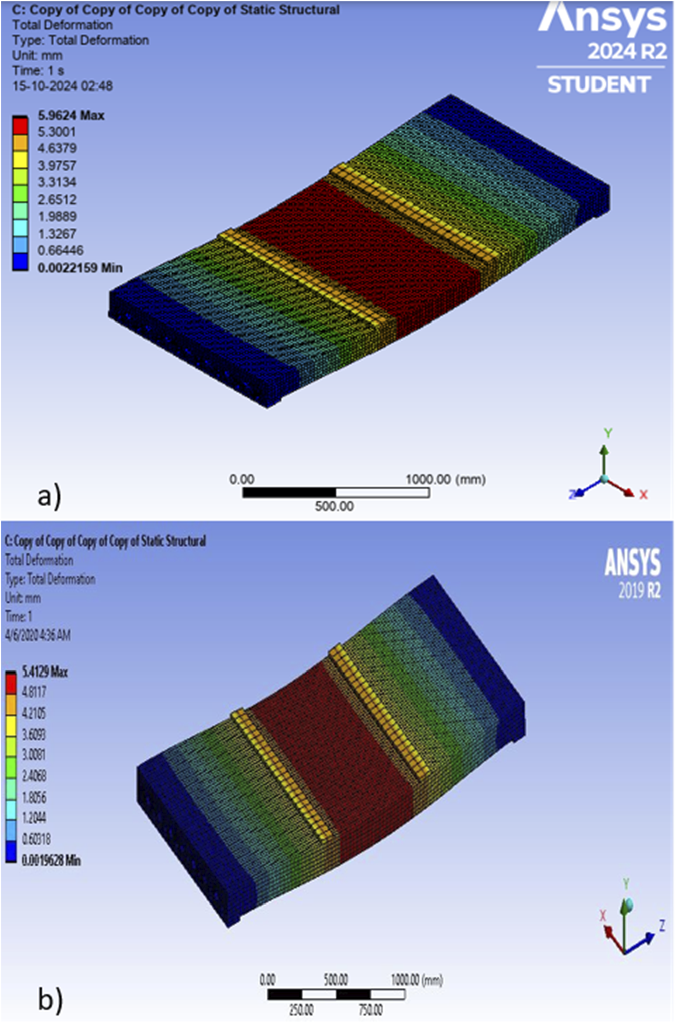
Comparing the effect of voids in reducing load carrying capacities in VCO and VCC with S1, it is noticed that VCC is superior as the load carrying capacity of it is more than S1 by 34.7%, but compared to the load carrying capacity of VCO is less by about 24%. These improvements are considered an advantage of VCC compared to both VCO and S1. Regarding deformation, it was equal to 5.9 mm in VCC, which is less than S1, VCO, and CD. It can be stated that VCC has less deformation compared to the other studied types of slabs, and that can be attributed to the effect of embossment and dimply. The existence of voids would reduce the weight of concrete, which in turn reduces the internal forces that are formed due to the bending approach of steel sheets with concrete attempting to remain straight. Based on this less detachment force on embossment and de-bonding between concrete and steel, it could be formed very well.
Voided composite slab with light-weight concrete (LVCC)
One light-weight voided composite slab (LVCC) was modeled, where expanded polystyrene bead EPS was used as a partial replacement for coarse aggregates, along with waste plastic fiber as a sustainable and environmentally friendly alternative to commercial concrete. In the analysis shown in Figure 18, the results were 510 kN and 5.4 mm for load-carrying capacity and deformation, respectively. Figure 19 is a comparison of the deflections in the VCC and the LVCC slabs. Comparison of the loads and deflections in the VCC and the LVCC slabs.
It can be clearly noticed that the ultimate load has dropped by almost 27.6% compared to the VCC, 31.1% compared to the CD, and increased by 31.4% compared to VCO. On one hand, the deformation of the slab is close to that of VCC slab and less than that of CD and VCO slabs, which indicates that the failure was due to slippage and the composite action was not fully applied. This refers to the fact that the use of light-weight concrete might be sufficient to reduce the self-weight, but it dramatically reduces the ultimate load of the slab.
Modes of failure
Figure 20 illustrates the failure mode in the VCC and LVCC slabs. Both slabs have developed the same failure pattern, which was due to the slippage of the steel sheet. Failure pattern of voided composite slabs: (a) VCC, (b) LVCC.
Flexural failure was not noticed, as the test was automatically stopped by ANSYS when the steel sheets reached their yield point. However, the crushing of concrete was observed under the loading point.
Ductility and stiffness characteristics
The VCC and LVCC slabs were examined to determine whether they retained the ductile property of CD. The deformation ductility ratio of CD was equal to 4.3, while it was 4.2 and three for VCC and LVCC, respectively. Based on that result, it can be stated that voided composite slabs’ behavior is in conformity with the ductile composite slabs’ behavior, which is one more advantage added to this new type of slab. Comparing the stiffness of CD with S1, VCC, and LVCC slabs, it can be concluded that the stiffness of CD is the highest, which can be explained by the fact that the presence of the steel sheet increases the tensile strength of the slab and reduces the deflection, which in turn develops the stiffness of composite slabs when compared to conventional solid slabs. Moreover, it can be deduced that the difference between the stiffness of CD and VCC is about 10%, which can be explained by the reduction in the compressive strength of concrete that is attributed to the presence of voids. However, the difference is considered small, and this leads to the conclusion that VCC has a similar stiffness property as that of composite slabs. The stiffness of LVCC has dramatically reduced compared to CD and VCC by approximately 36.5% and 29.3%, respectively, which is an expected result due to the reduction of the ultimate load and the increment of deflection.
Conclusion
A new type of slab called voided composite slab was analyzed using ANSYS Workbench. Nine simply supported slabs were categorized into four groups. Group A: a solid slab S1, Group B: three voided slabs with square, oval, and round-box shapes (VCS, VCO, and VCB, respectively), Group C: three composite slabs with three different profiled steel sheets (CD, CE, and CN), and Group 4: two voided composite slabs that are the result of the emergence of the voided slab and the composite slab that yielded the best analytical results using conventional and light weight concrete (VCC and LVCC). The slabs were modeled and analyzed, and the results were discussed on the basis of load-carrying capacity, deformation, failure modes, cracks and end slips, stiffness, and ductility. The results clarify that the voided composite slab can be a possible alternative to traditional slabs based on the following conclusions: 1. Voided slab with oval voids VCO has shown the best flexural performance compared to other voided slabs. Compared to the solid slab, the load-carrying capacity of VCO has decreased by 24%. 2. Due to the presence of voids, the concrete needed has been reduced by 576 kg and 35% compared to solid slab S1, which reflects on the CO2 emitted and causes a reduction of about 565.065 kg. 3. The shape of the void is important in the stress distribution and crack formation, which directly affect the ultimate load of the voided slab. 4. The composite slab CD has shown superior performance in terms of ultimate load compared to the other composite slabs, with a 38% increment compared to the conventional solid slab. 5. The behavior of the composite slab CD, whose steel sheet has embossment on the top and the web of the flange, as well as two dimples on the body of the steel sheet, to develop the bond between the concrete and the steel sheet is highly influenced by the embossments’ arrangement and the steel deck profile. The arrangement explains the better performance. 6. Voided composite slabs are the result of merging VCO and CD, as they both showed the best performance compared to their groups’ elements. Voided composite slab with conventional concrete VCC has an ultimate load that exceeded the ultimate load of VCO by 50.3%. 7. The ultimate load of VCC reduced by 4.7% compared to CD, which is expected due to the presence of voids in the slab. However, the self-weight of VCC is less than CD for the same reason. 8. Light-weight concrete using EPS bead and polypropylene waste plastic fibers in the LVCC slab caused reduction of ultimate load compared to the VCC slab by 27.6%. However, the deflection was so close. 9. VCC and LVCC have failed due to end slippage, which is similar to composite slab, and some shear cracks have occurred near the voids. 10. VCC have exhibited ductile behavior similar to composite slabs with a greater ductility ratio of 1.75 and 3.7, compared to S1 and VCO respectively. This makes this type of slabs very suitable to be used in construction where light weight, less deflection, and higher ductility are needed. 11. Using light-weight concrete in LVCC slightly reduces the ductility of the slab by a ratio of 1.4 compared to VCC. 12. It can be concluded that voided composite slab is a new type of slabs that combines the properties of the reduced weight with good flexural behavior as well as good ductility. These properties make voided composite slabs a strong competitive alternative to the other traditional types of slabs. 13. Further research is suggested to examine the performance of the slabs experimentally and to assess their economic features.
Footnotes
Declaration of conflicting interests
The author(s) declared no potential conflicts of interest with respect to the research, authorship, and/or publication of this article.
Funding
The author(s) received no financial support for the research, authorship, and/or publication of this article.