
Abstract
In order to address the problem of transition slip between the cylindrical segment and the ellipsoidal head segment of the carbon/carbon composite crucible preform with asymmetrical structure during the winding process, a winding pattern combining geodesic and non-geodesic is presented innovatively. Firstly, the formulae for the winding angle and the winding central rotation angle of the crucible cylindrical segment and the ellipsoidal head segment are established, and the fourth-order Runge-Kutta numerical method is employed for parametrical design. The two-tangent point winding path is determined by analyzing the effect of the cylindrical segment’s winding pitch, different ellipsoidal head segment heights, and slip coefficient on the winding angle. Secondly, the needle disk winding method is proposed to address the slight winding angle at the open end of the cylinder, making it easier to hang the yarn. Finally, the experiment on dry yarn winding of 3k carbon fiber (linear density: 198 g/km) is carried out. The results indicate that the relative error rate between the actual winding angle and the theoretical design angle differs by no more than 1.66%, demonstrating that carbon fibers can be stably and uniformly wound onto the surface of the carbon/carbon composite crucible preform. Compared to the traditional manual winding method, the winding pattern enhances winding efficiency, ensures carbon fibers’ uniformity and structural stability, and provides a new technological approach to producing high-performance composite materials.
Keywords
Introduction
With the rapid development of information technology and the photovoltaic industry, silicon material, with its excellent conductivity and semiconductor properties, occupies a core position in integrated circuits, solar panels, and other fields. 1 The preparation of monocrystalline silicon is crucial for semiconductor applications, and it highly relies on the performance of the crucible 2 . Although traditional graphite crucibles currently dominate the market, the limitations are in terms of stability, high-temperature resistance, and durability, especially the susceptibility to cracking and poor heat transfer performance. 3
Carbon/Carbon composites are extensively utilized in aerospace, energy, pressure vessels, etc., such as engine nozzles, hydrogen storage tanks, high-pressure gas cylinders, etc., due to their excellent thermo-mechanical properties, low coefficient of thermal expansion, excellent thermal conductivity, thermal flexural strength, ablation properties, and non-linear fracture characteristics.4,5 Carbon/carbon composite crucibles are becoming an excellent alternative to graphite crucibles, not only by demonstrating better heat resistance and longer service life but also by precisely meeting the specific needs of industrial sectors.
Carbon/Carbon composite crucibles are typically produced through a layer-by-layer process of carbon cloth and mesh tires, complemented by specialized needling techniques to construct a three-dimensional mesh structure. Nevertheless, the weaknesses in the interlaminar bonding strength and fiber damage inherent to this traditional approach must be addressed. The introduction of dry yarn winding technology is intended to address the challenges above by increasing the carbon fiber content between the preformed interlaminar. However, in practical implementation, the slippage of fibers in the end ellipsoidal head segment leads to accumulation issues at the pole of the ellipsoid, which poses higher requirements for the winding pattern. To this end, domestic and international scholars have conducted extensive research to optimize the fiber winding scheme.
Liang et al. 6 proposed a transitional layer design method for composite material pressure vessel shells with circular cross-segmental cores and elliptical end caps using a no-geodesic winding equation. Li et al. 7 designed a non-geodesic winding approach for carbon/carbon crucible preforms to achieve an integrated winding pattern for the cylindrical and ellipsoidal segments. However, the winding angle was set at the open end of the cylinder to 90°, which led to fiber accumulation and slippage issues. Wang et al. 8 conducted a thorough analysis of the effects of different tangent points on non-axisymmetric mandrels, successfully obtaining winding parameters that ensure both fiber stability and uniform distribution. Xu et al. 9 proposed a non-geodesic winding method suitable for spherical structures, leveraging differential geometry theory to derive the fiber structure equation for spherical configurations. Experimental validation through dry and wet winding methods effectively reduced fiber accumulation and bridging phenomena, significantly enhancing the strength and rigidity of spherical structures. Wang et al. 10 addressed composite elbow fittings by establishing fiber winding trajectory equations for cylindrical and annular cross-segments based on non-geodesic and geodesic winding methods. By optimizing parameters such as winding angles, they ensured uniformity in winding and stability in motion control.
Furthermore, Pakdel E et al. 11 reviewed the latest advancements in recycling carbon fiber reinforced composites (CFRC) and processing dry carbon fiber waste. Newcomb BA 12 comprehensively reviewed the entire process of carbon fibers from polymerization to spinning, stabilization, and carbonization. Shirvanimoghaddam K et al. 13 discussed the progress of the research in optimizing and utilizing carbon fiber processes. Dickson AN et al. 14 evaluated the tensile and bending mechanical properties of composite materials. Goh GD et al. 15 elaborated on fiber-reinforced composite materials processed through advanced manufacturing (AM) technology. Balla VK et al. 16 discussed the applications of various additive manufacturing (AM) technologies in processing polymer composite materials. Dackweiler M et al. 17 studied the friction behavior of dry carbon fiber tows in filament winding of structural profiles. Alexander Air et al. 18 innovatively developed AFP-V-type composite pressure vessels by combining automated fiber placement technology with geodesic winding methods. They proposed a strategy for controlling ply droop thickness and verified the reliability of the pressure vessel through 3D scanning. This technology has been successfully applied in automotive, small aerospace, and aviation tanks. Masahito Ueda et al. 19 meticulously classified voids generated inside high-pressure hydrogen tanks for fuel cell electric vehicles using dry yarn winding. They revealed optimization opportunities for fiber structure based on void location, cross-segmental area, and average size.
Although significant contributions have been made by predecessors in the study of carbon/carbon composite winding, research into winding technology for complex-shaped crucible preforms remains in the stage of manual winding. This study aims to fill this gap by innovatively designing winding methods combining geodesic and non-geodesic windings to achieve high-precision, high-performance preparation of carbon/carbon composite crucible preforms.
The paper investigates the winding patterns of carbon/carbon crucible preforms. First, a combined winding pattern of geodesic and non-geodesic windings is proposed, which derives the winding angle formulas for the cylindrical and ellipsoidal head segments based on the fiber winding parameters. Next, the influence of different pitch lengths, different head heights, and varying slip coefficients on the winding patterns is explored using MATLAB in the cylindrical segment; thereby, a reasonable winding pattern is determined and simulations are conducted. Finally, a needle disk system is designed to address the issue of smaller winding angles and more effortless fiber slippage at the open end of the cylindrical segment. The experiment verifies the feasibility and accuracy of this combined winding approach, using a four-axis carbon/carbon crucible preform winding machine. The series of studies enrich the preparation technology of carbon/carbon composite crucible preforms and opens up a new path for the fabrication of complex-shaped, large-scale preforms.
Optimization design of fiber winding pattern
Firstly, based on the structural characteristics of the cylindrical section and the ellipsoidal head section, a combined winding method is determined, where geodesic winding is used for the cylindrical section and non-geodesic winding is used for the ellipsoid head section. Subsequently, the winding angle and central rotational angle equations are solved separately for each section. The pitch’s effect on the cylindrical section’s winding angle is analyzed to determine the constant winding angle for this part. The influence of the cylindrical section’s pitch, the head section’s height, and the slip coefficient of the head section on the winding angle are analyzed. Optional parameters for winding are chosen to ensure that the starting winding angle of the head section matches that of the cylindrical section. Finally, the integration of geodesic and non-geodesic winding is accomplished.
Geodesic winding angle and central rotation angle of the cylindrical segment
Due to the cylindrical segment having a constant geodesic function, during the fiber winding process, the direction of the winding platform’s movement aligns with the axis of the crucible preform, and the distance between them remains consistent. Geodesics comprise numerous stable short lines, ensuring that fibers are tensioned between any two points on the preform surface without relying on friction to prevent slippage. Therefore, geodesics for winding ensures even fiber distribution across the preform surface. The winding process of the cylindrical segment is analyzed, as illustrated in Figure 1. The formula for an equal-diameter winding angle and winding central rotation angle is as equation (1). Schematic diagram of the winding process of cylindrical segment.

Equation (1) shows that the winding angle and central rotation angle in the cylindrical section of the crucible preform can be determined by the cylinder section’s diameter, pitch, and length, which provided an initial angle for the non-geodesic winding path on the ellipsoidal head section of the crucible preform.
Non-geodesic winding angle and central rotation angle of the ellipsoidal head segment
Since the C/C composite crucible preform is a short and thick shell, its gyration surface can be regarded as the rotation of the preform meridian around the Z-axis. Figure 2 illustrates the force analysis on a random point A on the fiber. The pressure FN generated by fiber tensioning can be decomposed into two components: force Fg along the geodesic curvature direction and force Fn along the normal curvature direction. If the pressure Fg along the geodesic direction does not exceed the maximum friction force Ff of the fiber, the fiber will not slip on the preform surface. In other words, the stable winding condition for the fiber is as equation (2). Fiber stress analysis.

The slip coefficient λ is defined as the ratio of Fg (the force component along the geodesic direction) to Fn (the force component along the normal curvature direction). The sliding friction coefficient μ is defined as the ratio of Ff to Fn.

Assuming the meridian curve equation of the preform is given by r(z) as Figure 3, then the parametric equation for the surface of the revolution of the preform can be expressed as (r(z)cosα,r(z)sinα,r). Using the z-coordinate and the winding angle α of the meridian curve equation as two parameters, the normal curvature Kn of the fibers is derived by applying differential geometry, incorporating the first and second fundamental forms of the surface. The geodesic curvature Kg can be derived from the Liouville formula.
20
Microfiber winding model diagram.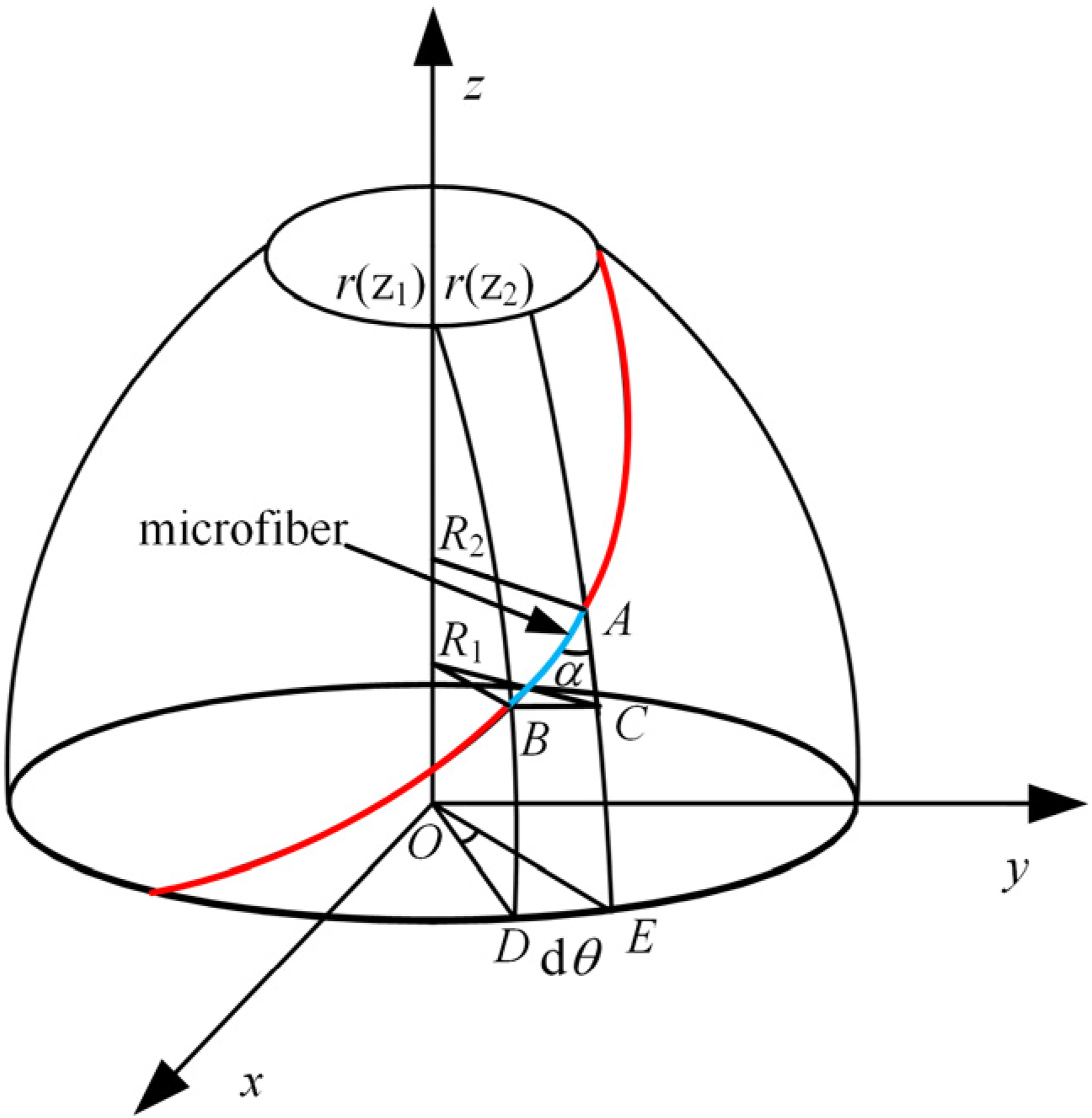

Substituting Equation (3) and Equation (4) into equation (2), the mathematical expression of the non-geodesic winding angle of the ellipsoidal head segment is as equation (5).
20

The center angle in the winding process determines the shape of the winding pattern and the speed ratio. The intersection between the winding line trajectory and the meridian is designated as point B. When the mandrel rotates dθ degrees, the angle of intersection between the meridian and the winding line trajectory at point A rotates θ+dθ degrees.
The projection analysis of the microfiber AC on the xoz plane is shown in. The meridian curvature radius of point A is defined as r1, the parallel circle radius is r, and the angle between the curvature ratio of two points in the microfiber AC is dθ. Thus, the relationship between the radius of the parallel circle and the center angle can be expressed as equation (6).

Taking the microfiber BC between the two meridians for analysis, as shown in Figure 4 and Figure 5, and combined with the relationship between the fiber BC and the winding angle a, the correlation between the winding angle a and the central rotation angle dθ is expressed as equation (7). xoz plane analysis diagram. xoy plane analysis.


Combined with Equation (6) and Equation (7), the central rotation angle of the fibers between any two parallel circles of the ellipsoidal head section of the non-geodesic pattern during the winding process can be determined as equation (8).

Parameterized design of winding factors
The influence of pitch on winding angle
To facilitate a smooth fiber transition during the winding process, it is essential to ensure a consistent winding angle at the transition section between the cylinder and the ellipsoidal head segment. The length-to-diameter D/L ratio in the cylinder section of the crucible preform is set as 2. Thus, the relationship between the winding angle of the geodesic winding and the pitch of the cylinder section is established using equation (1), as illustrated in Figure 6. The relation between winding Angle and pitch.
Figure 6 illustrates that the winding pitch decreases with the increase of the winding angle. Figure 7 depicts the simulation results with pitches equal to 1/4, 1/2, and 1 times the length of the cylindrical segment, respectively. The findings reveal that when employing half and quarter cylindrical pitches, the winding angles exceed 60°. In contrast, the winding angle with a full cylindrical pitch is notably lower, measuring precisely at 47.62°. An excessive winding angle results in fiber accumulation within the cylindrical segment, which deteriorates the smooth transition between the cylinder and the ellipsoidal head segment of the crucible preform. Consequently, a pitch equal to 1 times the length of the cylindrical segment is the most suitable. Cylindrical segment winding simulation: (a) 1 times pitch; (b) 1/2 times pitch; (c) 1/4 times pitch.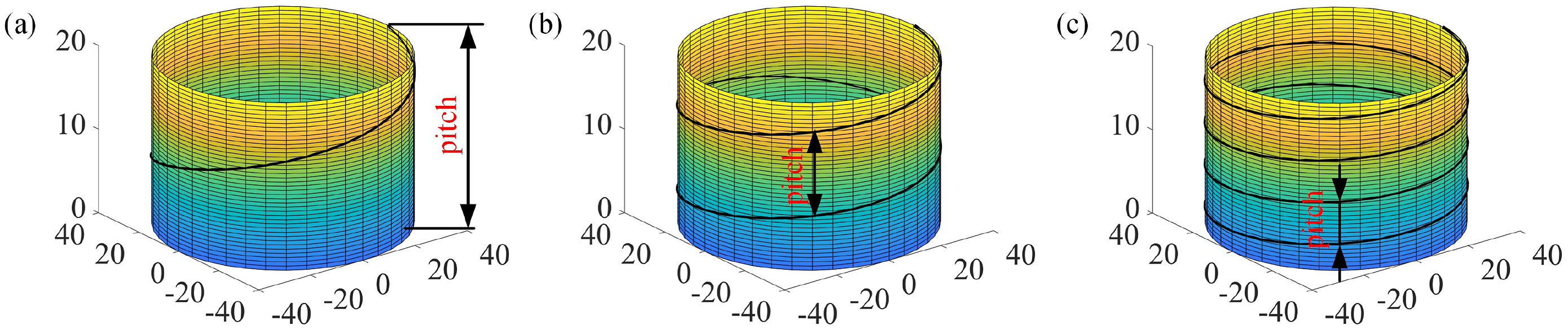
Influence of the ellipsoidal head height on the winding angle
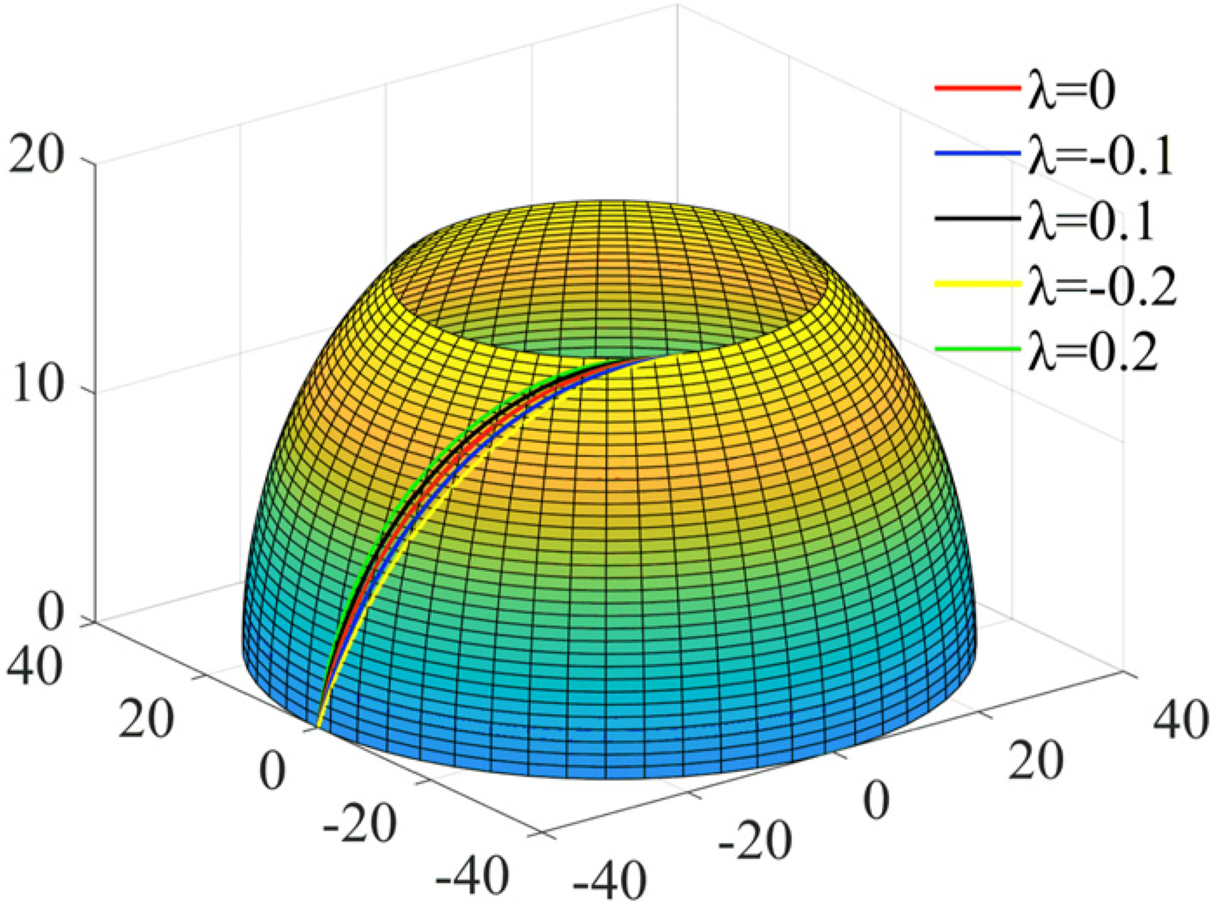
The fourth-order Runge-Kutta method is employed to solve the differential equation of the non-geodesic winding angle in the ellipsoidal head section, with different slip coefficients introduced into the equation. The winding angles of the standard ellipsoidal head with dimensions the MATLAB software solves a = 400 mm and b = 200 mm under different slip coefficients, namely l = −0.1, −0.2, 0, 0.1, and 0.2. The results are presented in Figure 9.
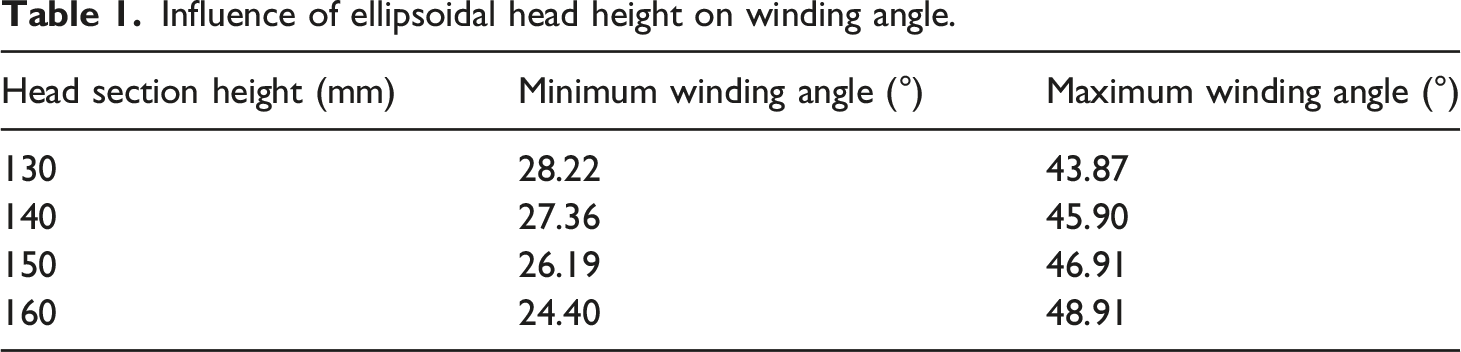
Figure 8 illustrates that as the height of the ellipsoidal head segment decreases gradually, the designable range of non-geodesic initial winding angle gradually shrinks. If the ellipsoid head height is too large, it does not conform to the single crystal silicon refining process requirement. If the ellipsoid head height is too small, the range of designable winding angles will be reduced. Using a winding angle of 90° at the poles of the ellipsoid as the design reference (Z = 16), we compare the range of initial winding angles at the ellipsoid head segment under different head segment heights: h = 160 mm (Z = 0), h = 150 mm (Z = 1), h = 140 mm (Z = 2), and h = 130 mm (Z = 3). The influence of the ellipsoidal head height on the winding angle is compared in Table 1. According to equation (1), the winding angle at the transition segment between the cylinder and the ellipsoidal head segment (the initial winding angle at the ellipsoid head segment.) is 47.62°. Thus, the optimal height of the elliptical head segment is 160 mm, and the most suitable slip coefficient value is −0.15. The winding angle varies with the head height under different slip coefficients. Simulations for the influence of slip coefficients on winding patterns in ellipsoidal head segment. Influence of ellipsoidal head height on winding angle.
Influence of slip coefficients on winding angle
The slip coefficient’s magnitude directly affects the winding pattern’s compactness and uniformity. Lower slip coefficients imply stronger friction between the material and the preform shaft, facilitating the formation of a denser and more uniform winding pattern, reducing gaps, and enhancing the overall strength and stability of the winding structure.
Using the non-geodesic stable winding equation in conjunction with the standard mathematical model of an ellipsoid with ellipsoidal head height ℎ = 160 mm, trajectory simulations for λ = −0.1, −0.2, 0, 0.1, and 0.2 were conducted, as shown in Figure 10. The winding angle at a given location varies with changes in the fiber slip coefficient. When λ < 0, this signifies that the fiber winding path deviates downwards from the geodesic path; as the Z-axis coordinate increases, the winding angle initially increases and then decreases. Conversely, when λ > 0, it indicates that the fiber winding path deviates upwards from the geodesic path; in this scenario, as the Z-axis coordinate grows, the winding angle decreases and subsequently increases. Two-tangent point winding path.
Optimal winding path
Upon completing a winding cycle, both the winding platform and the flipping mechanism must return to the initial winding position. Simultaneously, the starting point of the next winding operation must be offset by the width of a single line from the termination point of the previous winding, ensuring that fibers can be seamlessly connected at the ends during the winding process to form a continuous structure.
The center angle of the cylinder section is 30.95° (equation (2)), while the center angle of the ellipsoidal head segment is 29.55° (Equation (9)) and n is 2 (equation (10)). Employing a two-tangent point winding path can prevent the occurrence of a ‘birdnesting’ effect, fiber overlaps, bridging, and the generation of discontinuous stresses and unequal strains at the polar aperture of the head section, The shape of the two-tangent point winding path is illustrated in Figure 10. The fiber first passes through the cut point 1, then the preform rotates 180°, and the fiber is wound to the adjacent timing 2. It then proceeds sequentially through cut points 3 and 4. The winding path is precisely controlled. This technique ensures a more uniform distribution of fibers, particularly at complex geometrical transitions, enhancing the structural integrity and performance of the composite part.
Incorporating the optimal cylindrical segment pitch 𝑙𝑖 = 200 mm into equation (1), the ellipsoid head segment height h = 160 mm, and the slip coefficient 𝜆 = −0.15 into equation (6), integrating the cylindrical and ellipsoid head segments’ mathematical models, the trajectories of two-tangent point winding are simulated by MATLAB, as illustrated in Figure 11. Winding cycle diagram: (a) one cycle; (b) two cycles; (c) four cycles; (d) complete circulation.
A needle disk winding method with non-folding fibers
Optimal design of the needle disk structure
To achieve the optimal winding path and ensure the fiber can be evenly covered on the preform surface, a needle disk system is designed at the open end of the cylinder to achieve the demand of hanging yarn. During the winding process, carbon fibers are wound along the preform axial direction as the mandrel rotates. The winding platform, which is outfitted with a flipping mechanism, can move in both the radial and axial directions relative to the preform, ensuring the appropriate tensioning degree of the carbon fiber. Starting from the winding, the winding platform moves a predetermined distance as the preform rotates through one complete revolution. The carbon fibers follow a designed winding path, tracing a route from the cylindrical section’s opening to the ellipsoid poles and returning to the starting position. The doffing points of the fibers must be offset by at least one or n cylindrical segment angles relative to the preceding doffing start point. This process undergoes multiple cycles of reciprocating motion until the preform surface is uniformly covered with carbon fibers. Besides, to achieve the aforementioned winding process, the winding trajectory of the carbon/carbon crucible winding machine should follow the designed winding angle, the winding pitch of the cylindrical segment, the motion trajectory of the flipping mechanism, and other related technical parameters. The specific design process is as follows.
The winding angle depends on the number of needles between the two needle pins. By analyzing the two contiguous needle pins, the relationship between the winding angles of the cylinder segment and the number of pins can be obtained, as illustrated in Figure 12. Pin geometry.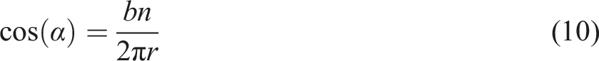
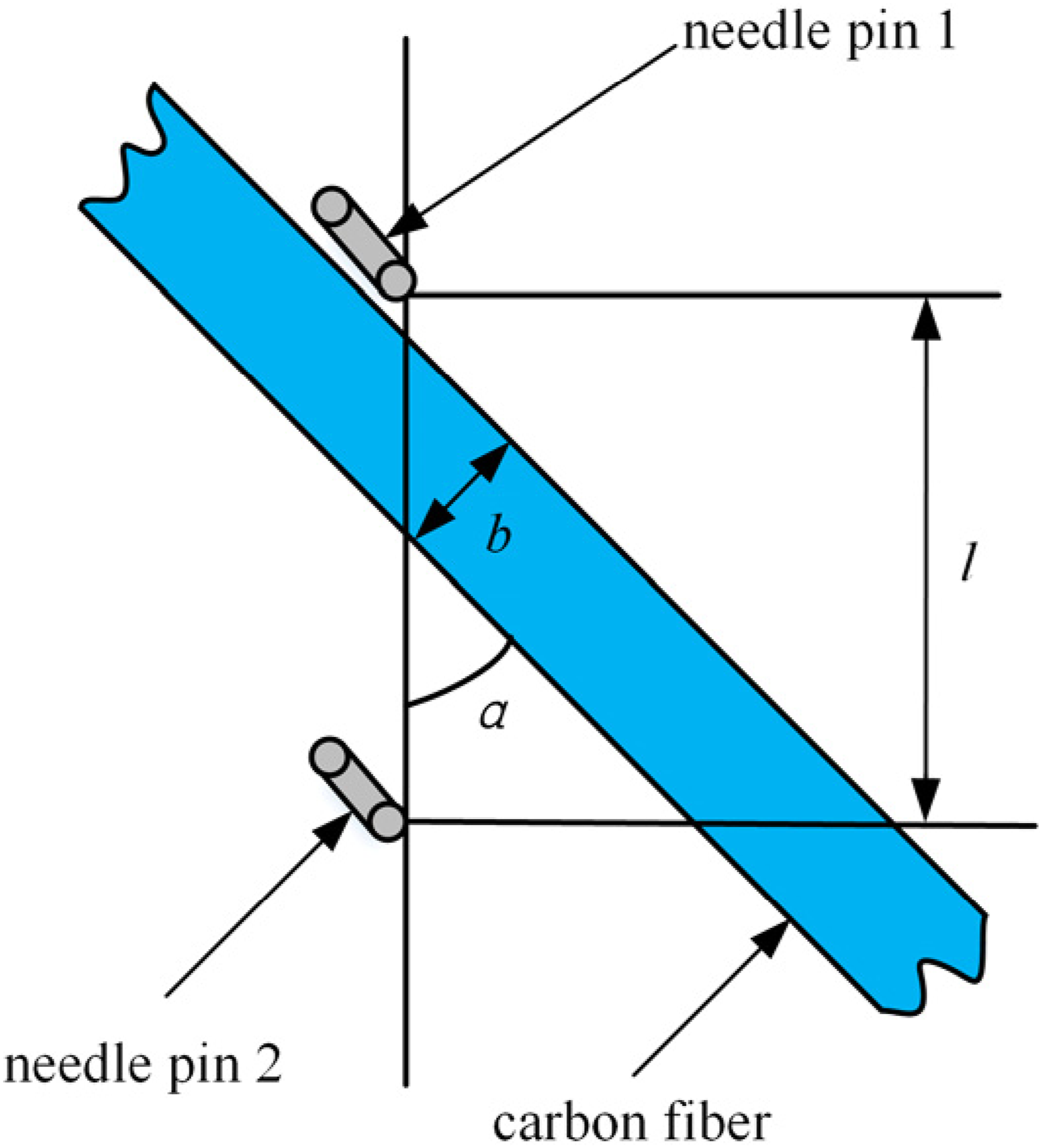
Influence of needle pins on fiber count.


Winding cycle diagram: (a) one round trip; (b) four round trips.
Experimental study on winding optimization
To verify the feasibility of designing winding patterns, set the diameter of the cylindrical segment d1 = 400 mm, the length l = 200 mm, the winding angle of the cylindrical section a = 47.62°, the height of the head section h = 150 mm, the pole of the ellipse diameter d2 = 200 mm in the experimental winding process. Based on the designed two-tangent point winding path, the experiment uses a carbon/carbon composite crucible preform four-axis winding machine to enwind the fiber around the 45 steel surface. The winding platform moves along the preform axis while also advancing in the radial direction of the preform, simultaneously coordinating with the flipping mechanism’s rotation around its pivot axis to conduct the winding experiment. The winding results are presented in Figure 14, demonstrating that the yarn meets the fiber end hanging and non-slip requirements at the transition section. Given that the coefficient of friction for carbon cloth and carbon fiber fabrics is significantly greater than that of 45 steel, this discrepancy substantiates the rationality of the designed winding pattern. Experimental winding process: (a) positive stroke winding; (b) negative stroke winding; (c) the complete cycle winding.
Furthermore, multiple measurements were taken of the cylindrical segment’s initial winding angle, the equatorial region’s transitional winding angle, and the ellipsoidal segment’s winding angle, as depicted in Figure 15. The winding angle of each section is summarized in Table 3, which shows that the maximum error between the experimental results and the theoretical winding angle is 1.66%. This error is within the allowable range in the winding process and further proves the accuracy of the proposed winding method in this study. Experimental measurement for the winding angle. Winding angle measurement results.

Conclusions
Based on the spiral winding method of the prefabricated crucible of non-symmetrical reinforced fiber, a novel winding method combined with geodesic and non-geodesic lines is proposed in this study. The main conclusions are as follows: (1) The issue of slippage between the ellipsoid head and cylindrical segments is analyzed, the influence patterns of various process parameters on the winding trajectory are investigated, and the overall winding parameters for the carbon/carbon crucible preform are derived, which deduct a rational winding path and subsequent simulations. The research establishes a solid foundation for optimizing trajectories in composite rotational bodies. (2) The needle disk structure is optimized, and experimental verification is conducted by applying the needle disk winding method with non-folding fibers. The results indicated that the relative error rate of the actual winding angle did not exceed 1.66%, thus validating the winding method’s correctness and the trajectory design’s feasibility, which perfected the design of winding trajectories for asymmetric carbon fiber preforms. (3) A proficient and precise fiber helical winding technology system suitable for asymmetric structure crucible preforms has been successfully established. Not only does this fill a research gap in the field, but it also paves the way for the extensive application of carbon/carbon composites in high-tech industries such as aerospace and semiconductor manufacturing.
Footnotes
Declaration of conflicting interests
The author(s) declared no potential conflicts of interest with respect to the research, authorship, and/or publication of this article.
Funding
The author(s) received no financial support for the research, authorship, and/or publication of this article.