
Abstract
A sandwich insulation wall panel is a novel composite wall that integrates load bearing, thermal insulation and decoration. Most of the wall materials of sandwich insulation wall panels are made of ordinary concrete or lightweight concrete, which causes the wall panels to be too thick and heavy, and there are problems associated with poor durability and high energy consumption. Textile-reinforced engineered cementitious composite (TRE) materials have excellent mechanical properties, toughness and durability. Therefore, a type of sandwich insulation wall panel (SIWP) was constructed using textile-reinforced engineered cementitious composites (TRE) as the inner and outer wythes. Its good crack control ability and tensile performance can compensate for the brittle cracking and shedding of ordinary concrete sandwich insulation wall panels. Through a four-point bending test, the bending performance of the TRE sandwich insulation wall panel (TRE-SIWP) was analyzed from three aspects: failure mode, load-midspan deflection curve and ductility. The research variables included the number of hot rain cycles, the thickness of the TRE wythes, the hot rain environment, the thermal insulation layer type and thickness, and the number of heating-freezing cycles. The results show the that hot-rain cycles had the least effect on the specimen with a rock wool board, and they caused more damage to the TRE wythes than they did to the insulation board. Increasing the thickness of the insulation layer and TRE width could improve the flexural bearing capacity and stiffness of the TRE-SIWPs.
Keywords
Introduction
A sandwich insulation wall panel (SIWP) is a type of insulation wall panel that integrates load bearing, thermal insulation and decoration; moreover, several high-efficiency insulation materials, such as expanded polystyrene (EPS), extruded polystyrene (XPS), and polyurethane (PU) can be placed between the inner and outer walls. A series of connectors penetrating through the insulation board connects three layers (i.e., the insulation layer and the inner and outer wythes) into an entire panel to achieve thermal insulation and energy savings. SIWPs reduce the energy consumption of exterior walls and help people maintain a more comfortable living environment.1,2 The degree of composite action of SIWPs can be divided into fully composite, partially composite, and noncomposite based on the transfer characteristics of loads between the inner and outer wythes. 3 As an envelope structure, SIWPs are subjected mainly to self-weight, wind loads and seismic loads. Under the action of wind loading and horizontal seismic loading, the force mode of wall panels usually involves bending. The wind load and horizontal seismic load exert compression or tensile loads on the outer wythes, which leads to a bending moment in the SIWPs when the boundary of the SIWPs is constrained. Therefore, many domestic and foreign scholars have studied the flexural performance of SIWPs.
Carbonari studied the flexural performance of lightweight SIWPs composed of concrete and an EPS insulation board. 4 The results show that the vertically inserted steel connectors made little contribution to the flexural stiffness of the SIWPs, and it was recommended that a certain angle be used when inserting connectors. Kim investigated the influence of the thermal insulation materials (EPS and XPS) on the flexural performance of SIWPs and reported that SIWPs using EPS as the insulation layer exhibited a greater composite action degree. 5 Amran tested the flexural performance of a precast foamed concrete sandwich panel (PFCSP). 6 It was found that the PFCSP had the characteristics of a fully composite wall panel before cracking and that it had the characteristics of a partially composite wall panel after cracking. Moreover, its crack development was similar to that of solid reinforced concrete panels and precast concrete sandwich panels. Colombo assessed the effect of accelerated aging on the flexural performance of SIWPs using textile-reinforced concrete (TRC) as the inner and outer wythes and the residual mechanical behavior of uncracked and precracked sandwich beams under 150 or 500 freeze‒thaw cycles. 7 The study revealed that the mechanical properties of the specimens did not deteriorate significantly, and the flexural stiffness of the specimens increased after 500 freeze‒thaw cycles due to the later hydration of the cement particles. Kazem researched the effect of load holding and outdoor exposure on the durability of precast concrete sandwich panels with fiber reinforced polymer (FRP) grids as connectors. 8 The results showed that the design strength of these sandwich panels should be limited to 30% of the ultimate shear strength to prevent creep under the action of load, while outdoor exposure had no significant effect on the ultimate shear strength of these sandwich panels.
The enclosed structure is usually directly affected by the external environment during the service stage, such as the structural expansion caused by temperature changes and the scouring effect of rainwater. Especially in summer, when the enclosed structure is washed by rainwater after being exposed to high temperature, the temperature of the outer wall will change sharply, and the temperature difference before and after rain may even exceed 50. 9 The outer wythes of SIWPs will be subjected to greater thermal stress and generate temperature cracks under the action of great temperature differences to damage the outer wythes and shorten their service life. 10 At the same time, the influence of alternating winter and summer conditions on the properties of SIWPs cannot be ignored. Therefore, the effects of both hot rain and heat-freezing cycles need to be considered when evaluating the durability of SIWPs. Munck carried out four-point bending tests to study the flexural performance of TRC sandwich beams after hot rain cycles, and the results showed that hot rain cycles led to continuous hydration of cement particles and premature failure of the textiles. 11 Based on the test data, Bruno researched the effects of temperature change and moisture content on the thermal performance of an external wall thermal insulation system and reported that with increasing wall aging and moisture content, the thermal resistance of the wall decreased, while the heat capacity increased. 12
The use of novel wall materials and novel insulation materials to improve the performance of SIWPs has attracted increasing attention. The wall materials used in SIWPs include foam concrete (FC), ordinary concrete (NC), self-compacting concrete (SCC), high-performance concrete (HPC), high-performance fiber reinforced concrete (HPFRC), glass reinforced concrete (GRC), reactive powder concrete (RPC) and ultrahigh-performance concrete (UHPC).6,13–25 Moreover, engineered cementitious composites (ECCs) and textile-reinforced concrete (TRC) have been proven to have excellent properties, but studies on the use of these two materials as wall materials for SIWPs are rare. As a novel cement-based composite, an ECC has ultrahigh ductility, toughness, durability and excellent tensile properties and is characterized by multiple cracks and strain hardening. Its tensile strain can reach 3%–7%, which is 200–500 times the ultimate tensile strain (i.e., 0.01%–0.02%) of ordinary concrete.26–28 However, the bearing direction of short fibers randomly distributed in the ECC matrix is unclear, which limits the application of ECC. As a novel fiber composite material composed of textiles and fine-grained concrete, TRC has high strength and toughness, as well as excellent corrosion resistance, freeze‒thaw resistance and impermeability, which can effectively improve the durability of the structure.29–31 However, the stiffness of TRC degrades obviously after cracking, and the interface debonding between the textiles and the matrix is severe, so that the textiles cannot fully utilize their mechanical properties. Therefore, to combine the respective advantages of ECC and TRC, several scholars have proposed a new type of fiber composite composed of an ECC matrix and textiles, which is called a textile-reinforced ECC (TRE). According to the existing research results, a TRE has better crack control ability and tensile properties than a TRC does, and changing the number of textiles, the treatment method of the textiles and the number of freeze‒thaw cycles will affect the flexural properties of TRE panels.32–34 In addition, basalt fiber reinforced polymers (BFRPs) are characterized by corrosion resistance, light weight, high strength, low thermal conductivity and low carbon environmental friendliness and can be used in SIWPs instead of ordinary steel connectors. 35
In summary, most of the wall materials of sandwich insulation wall panels are made of ordinary or lightweight concrete, which causes the wall panels to be too thick and too heavy, and there are problems associated with poor durability and high energy consumption. Several studies have been carried out on the use of TREs to reinforce other components, but few related studies have evaluated the use of TREs as the inner and outer wythes of SIWPs. Therefore, this paper proposes novel SIWPs with TREs as the inner and outer wythes and BFRP bars as the connectors, which are called TRE sandwich insulation wall panels (TRE-SIWPs). Moreover, most of the research on the flexural performance of novel SIWPs has been limited to the conventional environment. However, the surface temperature of sandwich insulation wall panels is extremely high in the summer in tropical regions. With the onset of the rainy season, the surface temperature of the wall panels will increase due to high temperatures and decrease due to rain washing, resulting in damage to the wall panels. Therefore, the flexural performance of TRE-SIWPs after hot rain cycles was studied, and the influence of different factors on the flexural performance of TRE-SIWPs was analyzed. Moreover, the results are compared with those of the TRE-SIWPs without hot rain cycles to analyze the degradation in the flexural performance of the TRE-SIWPs. In this regard, the TRE-SIWPs were first subjected to hot rain cycles, and the parameters of the TRE-SIWPs, such as the flexural bearing capacity and load-midspan deflection curves, were subsequently obtained via four-point bending tests to evaluate the flexural performance of the TRE-SIWPs.
Test design and preparation
Materials
Mixture ratio of the ECC matrix (kg/m3).


Stirring ECC

Thermal insulation panels.
Material properties of the thermal insulation materials.


Impregnated carbon-glass fiber hybrid braiding textiles.
Properties and geometric parameters of impregnated carbon yarns.

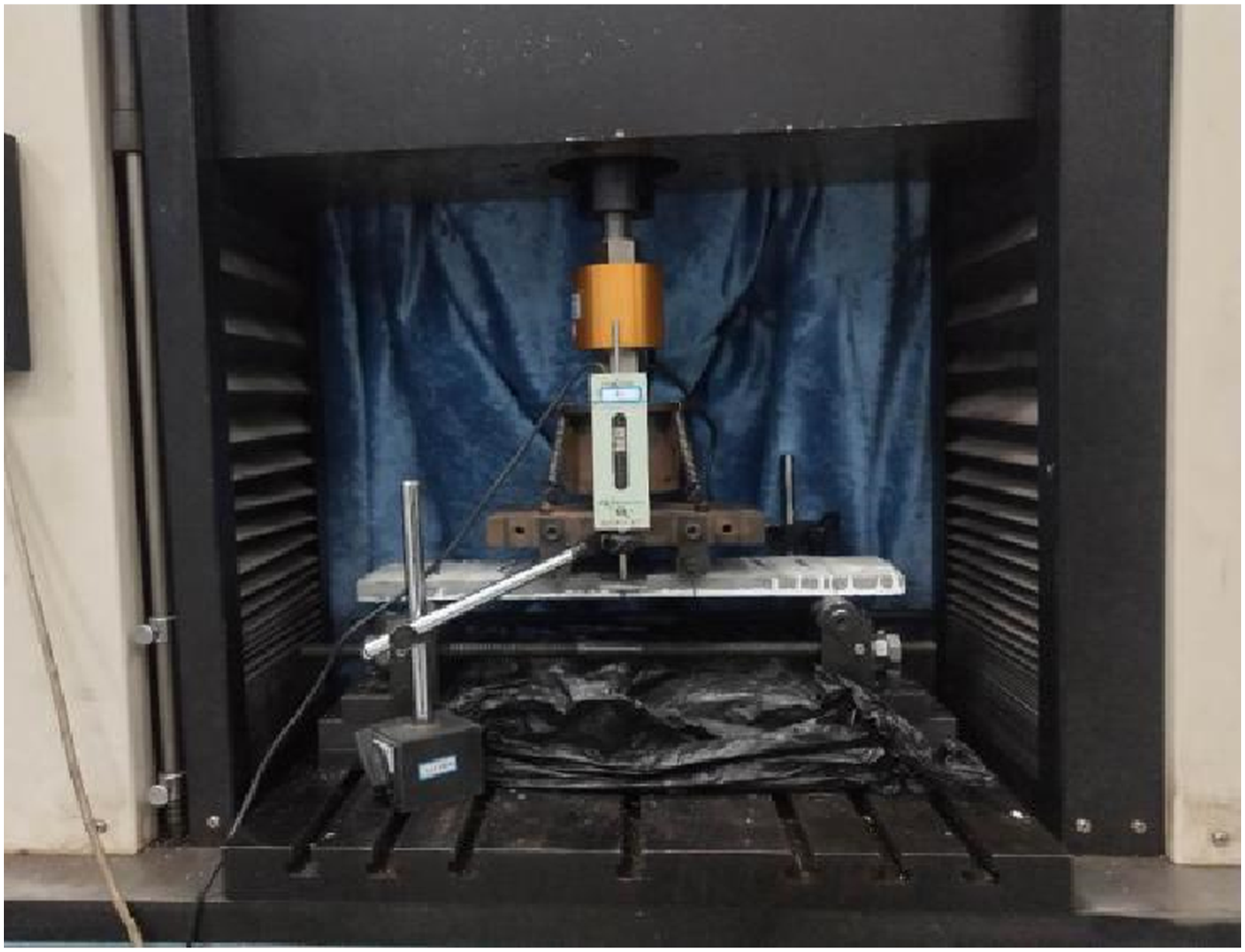
Four-point bending test loading device of the TRE panels.
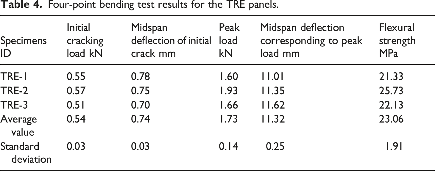
Four-point bending test results for the TRE panels.

Load-midspan deflection curve of the TRE panels.
Design and casting of TRE-SIWPs
The TRE-SIWPs studied in this paper consist of two TRE wythes and one thermal insulation board. A scale test was adopted in this study, and the size of the specimen was designed according to a span-to-thickness ratio of 15. The length and width of each specimen were 1200 mm and 300 mm, respectively. The overall thickness of each specimen varied with the thickness of the insulation board (i.e., 50 mm, 70 mm, 100 mm) and the thickness of the TRE wythes (i.e., 15 mm, 20 mm, 30 mm). The design details and connector layout of the specimens are shown in Figure 6, in which the angle of the inclined BFRP bars was 60°. Moreover, the anchoring depth of the BFRP shear connectors in TRE wythes was 20 mm, which is consistent with the anchoring depth mentioned in the literature.37,38 However, the anchoring depth of the BFRP shear connectors in the L80-X70-N-15*, L80-X70-N-20* and L80-X70-N-30* specimens was 15 mm. Design details and connector layout of the specimen (unit: mm).
The production of specimens was performed as follows. Before pouring, BFRP shear connectors were inserted into the insulation board. The formwork was cleaned and lubricated by demolding oil, after which the ECC matrix was poured, and the textile was placed in turn. After the pouring of the bottom TRE wythe was completed, the insulation board was immediately placed and gently pressed to ensure that the insulation board was fully bonded to the ECC matrix. Finally, the ECC matrix and the textile of the top TRE were poured and placed in turn. After pouring, the surface of the matrix was troweled to attain a smooth finish. The pouring process of the specimen is shown in Figure 7, and the details of the connectors inserted into the insulation board are shown in Figure 8. The formwork was dismantled 7 days after the pouring date, as shown in Figure 9. However, each specimen was cured for 28 days under standard conditions to ensure that its strength reached 90% of the design strength. Specimen pouring process. Insertion of BFRP bars. Specimen after demolding.


Testing program
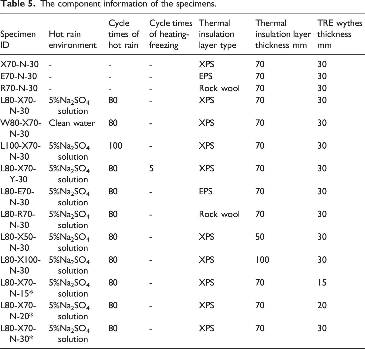
The component information of the specimens.
Hot rain cycle setups
Before the hot rain cycles, weather-resistant adhesive was applied to the surface of the exposed insulation board after curing to avoid damage to the insulation board caused by sprayed water or Na2SO4 solution. The hot rain cycles were carried out based on the weather resistance test method in JGJ144-2019. 39 Before each cycle, the temperature in the temperature cycle rain chamber was raised to 70°C for 1 hour. Water or a Na2SO4 solution was sprayed on the specimen for 1 hour after being kept at 70 ± 5°C for 2 hours. The water temperature was controlled within the range of 15 ± 5°C, and the water spray rate was controlled between 0.9 and 1.1 L/(m2·min). After spraying, each specimen was left to rest for 2 hours before the next cycle. All the specimens were removed after the end of the hot rain cycles and then left to stand naturally.
To simulate the excessive temperature difference between day and night that occurs in some areas, heating-freezing cycles were performed 7 days after completing the hot rain cycles, which was also based on the weather resistance test method of JGJ144-2019. 39 In each heating-freezing cycle, the temperature in the temperature chamber was raised to 50°C within 1 hour, and the temperature was held constant for 7 hours; then, the temperature was reduced to −20°C within 2 hours, after which the temperature was held at a constant temperature for 14 h. The temperature can fluctuate within the range of ±5°C at a constant temperature. In addition, inspections for cracks were conducted on the specimen after each heating-freezing cycle.
Test loading scheme
Four-point bending tests were also conducted to study the flexural performance of the TRE-SIWPs. Figure 10 shows the four-point bending test setups. The test equipment mainly included a 10T hydraulic jack, a 15T load sensor, five displacement meters with a range of 30 mm or 50 mm, a crack observation instrument and a static data acquisition instrument. In the tests, all the specimens were loaded in the same way. The specimen was supported by a fixed support and a sliding support to allow slight lateral slip. A steel plate 300 mm × 80 mm×10 mm in size was placed at each support and loading position on the specimen to avoid local compression failure. The load was applied through the hydraulic jack, and a load sensor was placed below the hydraulic jack to measure and control the load during the test. The force applied by the hydraulic jack was distributed to two steel tubes across the width of the specimen by using an I-beam, thus forming a two-line load. In addition, five displacement meters were used to measure the midspan deflection of the specimen, the vertical displacement at the support and the horizontal displacement of the upper TRE. Moreover, the cracking and failure of the specimen were observed and recorded during the test. Four-point bending test and measurement setups.
Since load control can accurately determine the load of a specimen when cracking begins, load control was adopted in this study. It was necessary to preload 2 kN to ensure close contact with the equipment in the device and to check whether the electronic instruments were working properly prior to load application. The load was reduced to zero after checking the instrumentation, and the load was gradually applied to the specimen in a step loading mode until the specimen was damaged. The load of each step was 1 kN and was maintained for 10 min, after which the cracking patterns on the surface of the specimen were observed and marked. Moreover, the loading stage at which the first crack appeared was determined as the initial cracking load of the specimen. Because the compressive strength of the insulation board is low, it had little effect on the flexural capacity, and the insulation was subjected mainly to shear action during the bending test. Therefore, the compression deformation of the insulation board was not measured in this study.
Test results and analysis
Failure modes
Figure 11 shows the surface morphology of the specimens before and after the hot rain cycles. After the hot rain cycles, no microcracks were found on the surface of any of the specimens, and the insulation material and TRE wythes did not shed, indicating that the integrity of the specimens was good. However, as shown in Figure 11(b), sulfate crystals precipitated on the surface of the specimens in the hot rain environment with 5% Na2SO4 solution. Comparison of the surface morphology of the specimens before and after hot rain cycles.
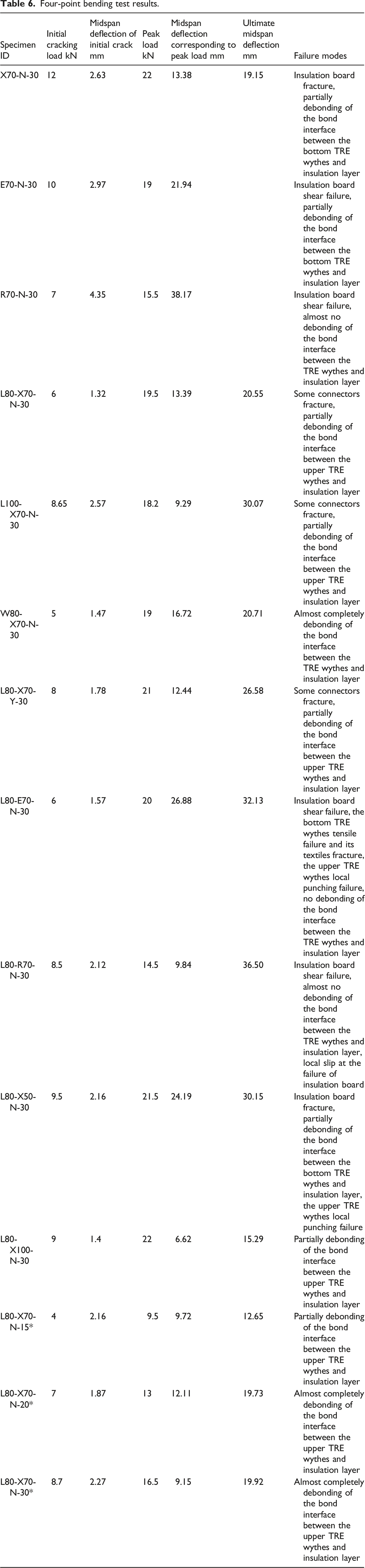
Four-point bending test results.

Failure morphology of specimens.
Discussion
The bearing capacity and the relationship between force and midspan deflection are important factors reflecting the flexural performance of TRE-SIWPs. At the initial stage of loading, the load and displacement gradually increase, and the load is shared by the TRE wythes and the insulation board. When the load reached the first peak, the joint between the insulation board and the TRE wythes was debonded, or the insulation board was shear damaged, which caused the load to decrease rapidly. Then, the cooperative working ability of the insulation board and the TRE partition was weakened. However, the utilization rate of textiles increased with increasing displacement, and the load also increased. When the load reached the second peak, the bottom layer of the textile broke, and the bearing capacity of the specimen decreased sharply. Subsequently, due to the existence of the second layer of the textile, the specimen would not be damaged instantaneously, and its bearing capacity could be maintained at a certain value for a long time. In addition, due to the contingency of the test, there may be some errors in the load-midspan deflection curves of the specimen after it reached its ultimate load. Therefore, the following section analyses the effects of six variables on the flexural performance of TRE-SIWPs in terms of bearing capacity and the general trend of the load-midspan deflection curve.
Effect of hot rain cycle times
Table 6 and Figure 13(a) show the test results and load-midspan deflection curves of the specimens under different numbers of hot rain cycles. With an increase in the number of hot rain cycles, the initial cracking load of the specimen increased by 44.17%, but the peak load decreased by 6.92%. The load‒midspan deflection curves of the two specimens almost coincided during the initial stage of loading, indicating that the number of hot rain cycles had little effect on the initial bending stiffness of the specimens. However, after the specimen that had undergone 100 hot rain cycles it had a higher initial cracking load and a larger midspan deflection of the initial crack. This might be because the sulfate ions continued to spread into the ECC matrix with increasing hot rain cycle time and reacted with the cement hydration products to generate expansion substances such as ettringite and gypsum, which filled the pores in the ECC matrix and improved the strength of the ECC matrix. After cracking, the flexural stiffness of the specimen after 100 hot rain cycles decreased significantly and was lower than that after 80 hot rain cycles, illustrating that the flexural capacity of the specimen decreased with increasing hot rain cycle number after cracking. Load-midspan deflection curves of the specimens after cyclic testing.
Effect of a hot rain environment
Table 6 and Figure 13(b) show the test results and load-midspan deflection curves of the specimens in different hot rain environments. Contrary to our expectations, the initial cracking load and peak load of the specimens that had undergone hot rain cycles in 5% Na2SO4 solution were greater than those in clean water, which increased by 20% and 2.64%, respectively, suggesting that the hot rain environment had a great impact on the initial cracking load. This initial cracking load increased because the expansion substances formed by the reaction of sulfate ions and cement hydration products filled the pores and microcracks inside the ECC matrix, which made up for the initial defects in the ECC matrix. The slope of the load-midspan deflection curve of the specimen after hot rain cycles in the 5% Na2SO4 solution was greater than that before cracking, further confirming that the hot rain cycles in the sulfate solution contributed to compensating for the initial defects in the ECC matrix and improving the initial flexural stiffness of the TRE-SIWPs. When the first bending crack appeared, the flexural stiffness of the specimen after hot rain cycles in clean water decreased rapidly, but that in 5% Na2SO4 solution decreased slowly. Finally, due to the debonding and separation of the TRE wythes and the insulation layer, the bearing capacity and the degree of composite action of the specimens decreased rapidly, resulting in specimen failure.
Effect of the thermal insulation type
Table 6 and Figure 13(c) show the test results and load-midspan deflection curves of the specimens with different insulation layer types after hot rain cycles. As shown in Table 6, among the three specimens without hot rain cycles, the specimen with a rock wool board as the insulation material had the lowest initial cracking load. However, after hot rain cycles, the specimen with a rock wool board as the insulation material has a higher initial cracking load than the other two specimens. Therefore, the rock wool board was least affected by hot rain cycles. After the specimen cracked, because the rock wool board had the lowest strength and earliest shear failure, the specimen with the rock wool board had the lowest ultimate load but better deformation ability. The peak load of the specimen with the EPS insulation board was not very different from that with the XPS insulation board, but the ultimate midspan deflection of the former was 56.35% greater than that of the latter. This might be because the EPS insulation board had excellent deformation ability and could work together with TRE wythes. Since the shear strength of the XPS insulation board was greater than that of the EPS insulation board, the bonding performance of the XPS insulation board with TRE wythes was poor, and the insulation board of the specimen whose insulation layer was EPS was subjected to shear failure, while the insulation board of the specimen whose insulation layer was XPS was the first to debond before the XPS insulation board failure.
Effect of the thermal insulation layer thickness
Table 6 and Figure 13(d) show the test results and load-midspan deflection curves of the specimens with three insulation layer thicknesses after hot rain cycles. Owing to the error in the pouring of the specimen with the 50 mm insulation layer, the thickness of the upper TRE wythe was greater, which caused its peak load to be greater than that of the specimen with a 70 mm insulation layer. Therefore, a specimen with a 50 mm insulation layer was not included in the comparative discussion here. Compared with that of the specimen with a 70 mm insulation layer, the initial cracking load of the specimen with a 100 mm insulation layer was 50% greater, the peak load was 12.82%, and the ultimate midspan deflection was 25.60%, indicating that increasing the thickness of the insulation layer was helpful for improving the flexural capacity and stiffness of the TRE-SIWPs. In the initial stage of loading, the slope of the load-midspan deflection curve of the specimen with a 100 mm insulation layer was the largest, illustrating that increasing the thickness of the insulation layer could also improve the initial flexural stiffness of TRE-SIWPs. In addition, the curve of the L80-X70-N30 was dropping significantly at 8 mm and then gain strength, which might be because debonding occurred between the insulation board and the TRE wythes at 8 mm, and then the bearing capacity of the textiles was brought into play with the increase of the deflection, improving the bearing capacity of the specimen.
Effect of TRE wythes thickness
Table 6 and Figure 13(e) show the test results and load-midspan deflection curves of the specimens with three TRE wythe thickness values after hot rain cycles. At the initial stage of loading, the load‒midspan deflection curves of specimens with 20 mm TRE wythes and 30 mm TRE wythes basically coincided, but the curve slope of the specimen with 15 mm TRE wythes was low. Therefore, increasing the TRE width thickness contributed to improving the initial flexural stiffness of the specimens, but this improvement decreased with increasing thickness of the TRE wythes. As shown in Figure 13(e), the specimen with a 30 mm TRE width had the largest initial cracking load. The curve slope of the specimen with a 20 mm TRE width decreased rapidly after cracking, suggesting that increasing the TRE width thickness could improve the flexural stiffness of the specimen when working with cracks. In addition, with increasing TRE width, the flexural capacity of the specimens improved, and the peak load of the specimen with a 30 mm TRE increased by 26.92% compared with that with a 20 mm TRE. However, the deformation ability of the specimen with 20 mm TRE wythes was better after reaching the peak load because it could maintain slow bending deformation.
Effect of heating-freezing cycles
Table 6 and Figure 13(f) show the test results and load-midspan deflection curves of the specimens before and after heating-freezing cycles after hot rain cycles. The specimen L80-X70-Y-30 represented that the specimen needed to experience five heating-freezing cycles after 80 hot rain cycles and stood for 7 days, while the specimen L80-X70-N-30 represented that the specimen had only been experienced 80 hot rain cycles. The load‒mid-span deflection curves of the specimens were almost identical regardless of whether heating–freezing cycles were conducted before specimen cracking occurred, so the heating–freezing cycle had no effect on the initial flexural stiffness of the specimens. After cracking, the specimens entered the working stage with cracks, but the flexural stiffness of the specimens after heating-freezing cycles did not decrease, and the peak load was 7.69% greater than that of the specimens without heating-freezing cycles. This indicated that the combination of 80 hot rain cycles and five heating-freezing cycles contributed to improving the flexural bearing capacity of the specimens, which was consistent with the conclusion drawn by Munck. 6 Therefore, conducting only hot rain cycles had a more serious impact on the flexural performance of the specimen than conducting both hot rain cycles and heating-freezing cycles.
Comparison of test results between specimens after hot rain cycles and without hot rain cycles
Table 6 shows the test results of the specimens under a conventional environment. For the specimens with an XPS insulation board, insulation board fracturing occurred in the specimen without hot rain cycles, and the peak load was greater, indicating that the damage from hot rain cycles to the TRE wythes and bonding interface was greater than that from the insulation board. For the specimens with an EPS insulation board, there was no serious damage or failure to the TRE wythes of the specimen that had not undergone hot rain cycles, which further supported the idea that the damage to the TRE wythes was more severe during hot rain cycles. For the specimens whose insulation material was rock wool, because the shear strength of the rock wool board was very low, even though the hot rain cycle caused greater damage to the TRE wythes, the bending strength of the TRE wythes was still greater than that of the rock wool board. Therefore, there was no phenomenon in which the TRE wythes of the specimen with the rock wool board were damaged under the bending load. Except for the specimen whose insulation material was EPS, the peak load values of the specimens after hot rain cycles were slightly lower than those of the specimens without hot rain cycles. This might be because of the local debonding of the specimens with the EPS insulation material without hot rain cycles, which reduced the degree of composite action of the specimens and thus lowered the bearing capacity of the specimens. Figure 14 shows the load-midspan deflection curves of the specimens in hot rain and conventional environments. In addition to the specimens with XPS insulation material, the curve slopes of the specimens increased after the hot rain cycles, which further indicates that the hot rain cycle could compensate for the initial defects of the ECC matrix and thus improve its stiffness. In addition, there were two peaks in the curve of the specimens after hot rain cycles, possibly because the failure of the specimens after hot rain cycles occurred in two places, and each place would cause a decrease in the curve. Comparison of the load-midspan deflection curves of the specimens before and after hot rain cycles.
Ductility analysis of specimens after hot rain cycles
Under the action of a bending load, the ductility of TRE-SIWPs under different test conditions varied. Ductility, an important index for evaluating the behavior of SIWPs, directly affects the failure mode and deformation ability of specimens. This paper utilizes the definition of ductility in the literature; that is, ductility in these sections was evaluated using the ductility index ∆u/∆y (where ∆u is the midspan deflection at the ultimate and ∆y is the midspan deflection at yielding).
19
Generally, yielding means that the material begins to suffer damage, and whether the specimen has suffered damage during the test was determined by observing whether the specimen has cracked. Therefore, since the specimens in this study did not have a yield stage, the midspan deflection at yielding was replaced by the midspan deflection at cracking. The calculation formula is shown as follows. Comparison of the ductility index of the specimens.

Table 6 lists the ductility indices for each specimen, and Figure 15 shows the comparison of the toughness index of each specimen under different variables. The ductility indices of the specimens significantly decreased with increasing hot rain cycle number, which once again indicates that hot rain cycles in sulfate solution could compensate for the initial defects in the ECC matrix and thus improve the initial flexural stiffness of the specimens. Moreover, the ductility of the specimens that had undergone hot rain cycles in clean water was greater than that of the specimens that had undergone hot rain cycles in sulfate solution, but the number of hot rain cycles had a more significant impact on the ductility. With increasing TRE width, the ductility indices of the specimens increased first and subsequently decreased; thus, increasing the thickness of the TRE wythes contributed to improving the ductility of the specimens when the TRE wythes thickness was low, but the ductility decreased with increasing TRE wythes thickness when the TRE wythes thickness increased to a certain value. Changing the thermal insulation type strongly affected the ductility of the specimens, which illustrates that the ductility of TRE-SIWPs is closely related to the strength and stiffness of the insulation material. The ductility indices of the specimens that had undergone 80 hot rain cycles and five heating-freezing cycles were lower than those of the specimens that had only undergone 80 hot rain cycles, indicating that adding five heating-freezing cycles would reduce the deformation ability of the specimens. In addition, the ductility of the specimens decreased with increasing insulation layer thickness, possibly because the shear stiffness of the specimens improved with increasing insulation layer thickness, thereby reducing the ductility.
Conclusions
Sandwich insulation wall panels with TRE as the inner and outer wythes were evaluated. The effects of six variables (i.e., hot rain cycle time, hot rain environment, thermal insulation type, thermal insulation layer thickness, total abrasion time, TRE width and heating-freezing cycles) on the flexural performance of TRE-SIWPs after hot rain cycles were studied via four-point bending tests. The results show that the specimens still had high bearing capacity and ductility after hot rain cycles, which indicated that the use of TRE-SIWPs to replace ordinary sandwich insulation wall panels can improve the durability of structures. However, to ensure that TRE sandwich insulation wall panels can be applied in practical engineering, it is necessary to study their shear and thermal performance. Due to the limitations of test conditions, it is difficult to carry out hot rain cycles and bending tests on full-scale TRE-SIWPs. Therefore, the specimens in this study were scaled according to the span-to-thickness ratio of the actual wall, and the results can reflect the flexural performance of the large structures to a certain extent. However, it is still necessary to further study full-scale structures through finite element analysis or optimization of the test conditions; therefore, we will study the impact of specimen size on the test results in future work. Moreover, the shear strength values of the insulation layers were significantly low, and without sufficient shear-resistant construction measures, the insulation board and the TRE panel will inevitably debond. According to the test results of the study, even though 45° BFRP connectors were set in the specimen to support the shear load, the debonding between the insulation board and TRE panel was relatively severe. Therefore, further studies of the connectors of sandwich insulation wall panels are needed. In summary, the following conclusions are drawn from the results of the study. (1) Hot rain cycles caused more damage to TRE wythes than to insulation boards. The flexural bearing capacity of the specimen with the rock wool board was the lowest, and the ultimate flexural capacities of the specimens with the XPS or EPS insulation layer were not very different. (2) Compared with that of hot rain cycles in clean water, the initial flexural stiffness of the specimen that had undergone hot rain cycles in sulfate solution was greater, and it improved with increasing hot rain cycle time. This verified the view that sulfate ions diffuse into the ECC matrix and react with cement hydration products to generate expansive substances, compensating for the initial defects in the ECC matrix. Therefore, TRE-SIWPs had good resistance to sulfate corrosion. (3) Increasing the thickness of the insulation layer and the TRE width contributed to improving the flexural capacity and stiffness of the TRE-SIWPs, but the deformation capacity was weakened accordingly. Moreover, only conducting hot rain cycles had a more serious impact on the flexural performance of TRE-SIWPs than both conducting hot rain and heating-freezing cycles. (4) After hot rain cycles in sulfate solution, the specimens had lower ductility than after hot rain cycles in clean water. The thickness of the insulation board and the TRE width had opposite effects on the ductility of the TRE-SIWPs. The ductility of TRE-SIWPs was closely related to the type of thermal insulation material. In addition, adding five heating-freezing cycles reduced the deformation capacity of the TRE-SIWPs. (5) TRE-SIWPs have the advantages of excellent ductility and superior cracking performance, and they still have a high bearing capacity after hot rain cycles. However, at present, the price of the raw materials used for making ECCs is high, so we will adjust the raw materials used for ECC to reduce the cost of the TRE-SIWPs.
Footnotes
Acknowledgements
The authors gratefully acknowledge the financial support from the Xuzhou Key Research and Development Program (Industry Prospect and Common Key Technology) (KC18106), the Postgraduate Research & Practice Innovation Program of Jiangsu Province (KYCX23_2739) and the Graduate Innovation Program of China University of Mining and Technology (2023WLJCRCZL049). The experimental work described in this paper was conducted at the Jiangsu Key Laboratory of Environmental Impact and Structural Safety in Civil Engineering at the China University of Mining and Technology. Assistance of the staff and students of the laboratory during the testing is acknowledged and greatly appreciated.
Declaration of conflicting interests
The author(s) declared no potential conflicts of interest with respect to the research, authorship, and/or publication of this article.
Funding
The author(s) disclosed receipt of the following financial support for the research, authorship, and/or publication of this article: This work was supported by the Xuzhou Key Research and Development Program (Industry Prospect and Common Key Technology) (KC18106), Postgraduate Research & Practice Innovation Program of Jiangsu Province (KYCX23_2739), Graduate Innovation Program of China University of Mining and Technology (2023WLJCRCZL049).