
Abstract
An air gap in thermal protective clothing (TPC) plays an important role in determining heat transfer, but it may also increase the amount of stored thermal energy that would discharge to the skin after exposure, especially when the TPC suffers compression. To investigate the effect of air gap and compression on the dual thermal protective performance (TPP), thermal hazardous performance (THP) and overall thermal protective performance (OTPP) of TPC, nine air gap configurations with different sizes and positions and five compression levels were designed in this study. Regression models were established to explore the relationships among air gap size, compression and THP for different air gap positions. The results demonstrate that increasing the air gap size without exceeding 12 mm not only significantly enhances the TPP by impeding heat transfer from the heat source to the fabric system during exposure but also decreases the THP by reducing heat discharge from the fabric system to the sensor even when compression is applied. Although an inner air gap contributes more to increasing the TPP during exposure than an outer air gap, it may also bring about severe stored energy discharge when compression is applied. It suggests that a larger air gap size should be divided into individually separate air gaps within different fabric layers to reduce the heat transfer during exposure as well as lower the stored thermal energy discharge after exposure.
Introduction
Thermal protective clothing (TPC) is an essential personal protective equipment with the capability of protecting the personal safety of workers by impeding heat transfer from thermal exposure.1,2 Currently, thermal exposures of firefighters, who act as the first responders to unwanted fires and rescue victims, have become complex within a wide range of possible thermal hazards (conduction, convection, hot liquid, steam, and/or hot solids). TPC made up of multilayer fabrics, typically consisting of an outer shell, a moisture barrier, and a thermal liner, has been widely equipped throughout the world.3,4 The outer shell made of flame-resistant synthetic fibers represents the first line of defense from incoming threat agents. 5 The moisture barrier with a membrane bonded to a lightweight layer of flame-resistant fibers protects the human body from hot liquid, steam, etc., while allowing the sweat vapor generated from firefighters to dissipate and debilitate heat stress. The thermal liner manufactured by a batting fabric enhances the overall thermal insulation characteristics of protective clothing.6,7 The multilayer TPC could certainly provide high thermal protective performance during exposure, but it also stores a larger amount of thermal energy that continues to discharge onto human skin as a passive heat source after exposure, significantly reducing the thermal protective performance of TPC and probably even causing more serious skin burns.8,9 Therefore, the dual thermal-protective and thermal-hazardous performance of multilayer TPC should be comprehensively studied to ensure its reliability.
In previous studies, scholars investigated the effects of exposure conditions, fabrics’ properties, and moisture on the overall thermal protective performance of TPC. Mandal et al. 10 found that the types of thermal exposure have different effects on the thermal protective performance of fabric systems. The study by He et al. 11 found that the amount of stored energy of fabric systems would increase with heat source intensity and exposure time, while the stored energy released to the skin would be limited even with a high exposure duration. Song et al. 12 showed that thick and multilayer fabric systems provided better thermal protective performance during exposure, but more stored energy was discharged to human skin after exposure, thereby exacerbating skin burns. The wearer’s sweat causes moisture to be contained in TPC, with regards to the effects of moisture on the thermal protective performance of TPC. The study by Barker et al. 13 showed that 15% moisture decreases the 2nd degree burn time of the fabric system, and the protective properties of TPC become worse as well, which is due to the increasing thermal conductivity of TPC by the moisture. However, when the moisture content exceeds 15%, the thermal protective performance of TPC experiences a recovery and even an increase because the moisture has greater specific heat to store more thermal energy within the fabric system but allows less heat to pass through it. 12
To ensure that high-temperature workers are not hindered in their actions during work, TPC is generally designed with a loose structure, naturally producing air gaps between the TPC and human body. 14 Studies have shown that still air with low thermal conductivity plays a positive role in impeding heat transfer to human skin and an air gap below an optimal size can enhance the thermal protective performance of TPC. 15 The size and position of gaps are important factors affecting the thermal protective performance. The thermal protective performance of TPC increases with increasing air gap size, but some studies have shown that when the air gap size exceeds 7 mm, more convective heat transfer occurs within the TPC, and the role of the air gap in enhancing the thermal protective performance of TPC is weakened.16,17 Wang et al. 18 showed that a multilayer fabric system with a large air gap located in the inner position had greater thermal protective performance. This conclusion was confirmed by the study of Fu et al., 19 who also found that the two separate air gaps in a multilayer fabric system could further enhance the thermal protection of TPC. However, if compression is applied to a fabric system with an air gap, the amount of heat received by the sensor would increase dramatically. Nevertheless, these studies only considered the thermal protective performance of the fabric during exposure but ignored its thermal hazardous performance due to stored energy discharge after exposure.
There are two ways to discharge the stored energy from the fabric system: natural heat discharge and forced heat discharge by compression.20,21 The physical activity of workers, e.g., crawling, squatting, bending and leaning against a wall, may cause TPC to compress against human skin, accelerating the discharge of stored energy after exposure and even perhaps causing skin burns. Su et al. 22 found that compression significantly enhanced the thermal hazardous performance of TPC, and only by applying for 1.5 psi compression, the 3rd degree burn time was shortened by 44.6% after exposure. To comprehensively evaluate the stored energy of fabrics during exposure and the discharge of energy storage after exposure, the ASTM Technical Committee has introduced the test standard ASTM 2731-2018. 23 This standard suggests that the fabric with a 6.4 mm air gap positioned between the fabric and the sensor should be compressed at a compression of 13.8 kPa after exposure to the heat source.
In conclusion, although there have been many breakthroughs identifying the influencing factors on the thermal protective performance of TPC, existing studies examining the effects of air gaps rarely consider the thermal hazardous performance of TPC caused by stored energy discharge, which is especially complicated due to the application of compression. The air gap size, positions and compression levels are variable in actual use, and therefore, it is necessary to have a more comprehensive understanding of the dual performance changes due to the air gap size, positions and different levels of compression.
The purpose of this study is to perform laboratory simulations to investigate the effects of air gap size, position and compression on the dual thermal protective and thermal hazardous performance of TPC under low radiant heat exposure. The dual performance of the fabric system was quantified by several indicators and a stored thermal energy factor was introduced to examine the contribution of stored thermal energy. Regression analyses were established to investigate the relationships among the air gap, compression and thermal hazardous performance. The results of the study will help to understand the factors affecting dual performance and provide guidance for the design and development of thermal protective clothing.
Experiment
Materials
Basic properties of the selected fabrics.

Testing apparatus
To evaluate the effects of air gap and compression on the dual thermal-protective and thermal-hazardous performance of a multilayer fabric system under low radiant thermal exposure, a radiant protective performance test apparatus was modified, as shown in Figure 1(a). This modified apparatus consists of a low radiant heat source, a specimen holder, a sensor, a fabric compression device, a transfer tray, and a data acquisition system. The heat source uses a black ceramic heat plate to produce low radiant heat flux in accordance with test standard ASTM F2731-18.
23
A water-cooled sensor (Medtherm, United States) is located at the back of the test specimen and mounted in the center of a sensor holder to measure the heat flux transferred through the fabric to the skin. The transfer tray is designed to move the combined specimen holder and sensor between the heat source and the compressor assembly for continuous control of heat exposure and cooling. Testing apparatus: (a) major apparatus components; (b) fabric compressor assembly.
A schematic diagram of the fabric compressor assembly is shown in Figure 1(b). The compression device mainly consists of a compression block, an air cylinder, and a solenoid valve. To apply compression, a solenoid valve is activated to push the cylindrical compression block against the specimen. The compression on the surface of the compressor block can be adjusted by varying the air compression on the cylinder.
Design of experimental variables and test protocol
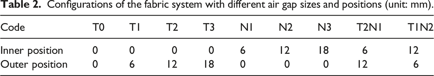
The specimen was placed in a standard atmosphere of 21°C with 65% relative humidity for 24 h before the test. To investigate the effect of the air gap size and position, experiments were conducted using thermal insulating spacers with different thicknesses. The position of the air gap is shown in Figure 2. It has been reported that approximately 65% of the air gap size in TPC is below 20 mm.7,24 Therefore, the range of air gap sizes used in this study was 0-18 mm, with an increase of 6 mm to simulate different air spaces entrapped in TPC. In total, nine air gap configurations were designed for the experiments, as shown in Table 2. During the process of exposure, the specimen was heated continuously for 120 s under a radiant heat source with an intensity of 8.5 kW/m2. The intensity of this low radiant heat met the requirement of ASTM F2731-2018. Then, the specimen was transferred by the tray to follow a forced cooling procedure. According to ASTM F2731-18, at the ease of thermal exposure, the tray transfers the specimen away from the heat source, and then the compression block compresses against it immediately. Five different compression levels (i.e., 0 kPa, 3.5 kPa, 6.9 kPa, 13.8 kPa and 21 kPa) were applied to simulate the compression that may be encountered by wearers.
22
The water-cooled sensor continuously records data during cooling for 60 s. Diagram of air gap positions. Configurations of the fabric system with different air gap sizes and positions (unit: mm).
Performance evaluation indices
Thermal protective performance during exposure
Two indices, including the 2nd degree burn time (t2nd) and the heat absorption of the sensor during exposure (EAE), were used to evaluate the thermal protective performance of TPC. A skin bioheat transfer model and the Henriques burn integral model were used to predict the skin burn time.23 The Henriques burn integral model is determined as: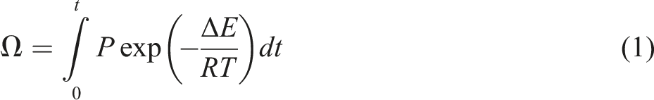
Skin energy absorption (EAE) was obtained by integrating the heat flux of the sensor with the corresponding exposure time:
Thermal hazardous performance after exposure
After exposure, the sensor recorded the thermal hazardous performance caused by the heat discharge from the fabric to the skin. Here, the energy discharge amount to the skin or energy absorption during cooling (CAE) was calculated as:
Overall thermal protective performance throughout the test
Total energy transmission (TAE) throughout the test was calculated by the sum of EAE and CAE:
Results and discussion
Effect of air gap size
Figure 3(a) compares the effects of air gap size on the TPP indicated by t2nd and EAE. When the fabric system is exposed to low-level radiant heat, the air gap size has a significant effect on the TPP of the fabric systems (p < .05). In general, t2nd increases with increasing air gap size, and EAE decreases with it. As shown in Figure 3(a), T1 with a 6 mm air gap at the outer position increases t2nd from 97.5 s to 136.3 s and decreases EAE by approximately 26.3%. As the air gap size increases to 12 mm, EAE is further reduced by 41.4% from 232.8 kJ/m2 to 136.4 kJ/m2. The existence of the air gap enhances TPP because the thermal conductivity of still air is quite low, which makes it difficult for a large amount of heat to pass through but instead to be stored in the fabric system.16,25 However, with further increases in the air gap size from 12 mm to 18 mm, the EAE of T3 is not significantly reduced (p > .05). Previous studies have noted that a large air gap size may enhance the air flow inside the air gap, increasing the role of thermal convection in heat transfer and weakening the positive effect of the air gap size.16,19 Comparison of performance for fabric systems with different outer air gap sizes: (a) t2nd and EAE; (b) CAE and TAE (Note: NS = no significant difference was observed at p > .05; otherwise, significant differences were noted among different air gap sizes (p < .05). When t2nd = 180 s, no burn occurred throughout the test.).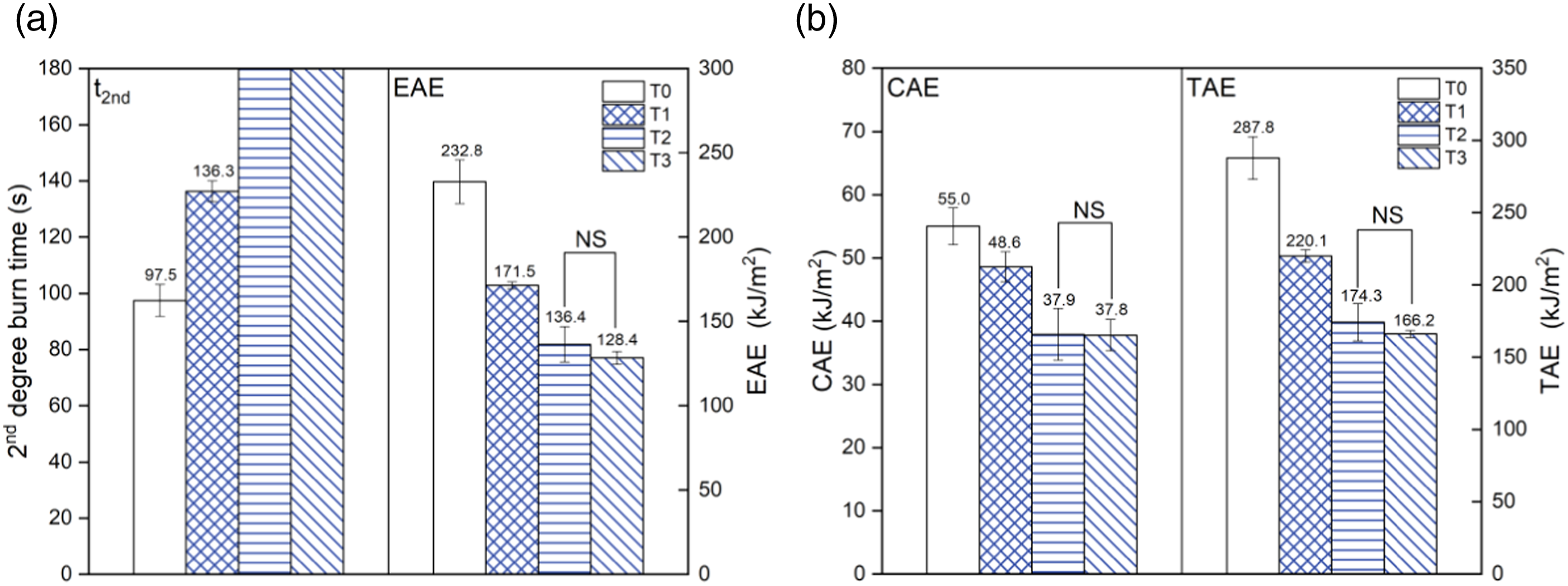
Figure 3(b) compares the THP expressed by CAE. The CAE of the fabric system of T1, T2 and T3 significantly decreased by 24.6% on average after the installation of the air gap, which indicates that the air gap also reduces the THP by slowing the heat discharge from the fabric system to the sensor after exposure. Notably, there is no significant difference in CAE between T2 and T3 (p > .05). The reason may be that although the larger air gap size in T3 increases the amount of stored thermal energy with the fabric system during exposure, 11 it also results in greater thermal resistance in impeding heat discharge from the fabric system to the sensor.
The data in Figure 3(b) show that increasing the air gap from 0 mm (T0) to 12 mm (T2) significantly reduces the TAE of the fabric system because the air gap size reduces the heat absorption of the sensor during both exposure and cooling, which ultimately shows a better overall thermal protective performance (OTPP). As the EAE and CAE between T2 and T3 do not differ significantly, their TAE results also show no significant difference.
Effect of air gap position
The effect of the air gap position on the performance of the fabric system is shown in Figure 4. Figure 4(a) shows that when the air gap size does not exceed 12 mm, an inner air gap has a significantly greater influence on TPP than an outer air gap (p < .05). Specifically, the EAE results of N1 and N2 are approximately 16.6% and 16.8% lower than those of T1 and T2, respectively. This can be explained by the results from Fu’s study, which shows that the inner air gap located away from the radiant heat source had a higher thermal resistance than the outer air gap.
26
This enhanced positive effect of the inner air gap can also be explained by the stored thermal energy in the fabric system during exposure. The inner air gap is located in direct contact with the sensor, which greatly impedes heat transfer from the heat source to the thermal liner, the moisture barrier, and the outer shell and ultimately allows more thermal energy to be stored within the whole fabric system. However, the outer air gap that is close to the outer shell can largely resist heat transfer from the heat source to this fabric layer and mainly stores thermal energy within it.
11
It can be concluded that the inner air gap has a significantly positive impact on TPP in reducing EAE compared to the outer air gap. The advantages of an inner air gap in enhancing TPP can also be proven by the index of t2nd, showing that the t2nd of N1 (i.e., >180 s) is significantly higher than that of T1 (i.e., 136.3 s). When the air gap size further increases to 18 mm, the EAE between N3 and T3 and between T2N1 and T1N2 do not differ significantly by air gap position (p > .05). This suggests that for a total large air gap size of 18 mm, heat transfer through the fabric system tends to be dominated by the size of the air gap rather than by its location. Notably, both T2N1 and T1N2 have significantly lower EAE than N3 and T3 (p < .05), although their total air gap sizes all reach 18 mm. For instance, the EAE of T2N1 was 87.7 kJ/m2, which is approximately 24.4% lower than that of N3 (i.e., 116.0 kJ/m2). N3 and T3 have only one air gap, whereas T2N1 and T1N2 have two air gaps distributed within different fabric layers, which enhance the positive effect of the still air gap. He et al.
27
investigated the effect of two separate air gaps within the fabric system on TPP under hot steam exposure and found that the inner air gap enhanced TPP more significantly than the middle air gap. This conforms to the results obtained from this study. Therefore, it is suggested that for a large air gap size (e.g., 18 mm) within a multilayer fabric system, it is better to divide it into separate air gaps within different fabric layers to largely reduce heat absorption of the skin during exposure. Comparison of performance for fabric systems with different air gap positions: (a) t2nd and EAE; (b) CAE and TAE. (Note: NS = no significant difference was observed at p > .05; otherwise, significant differences were determined among different air gap sizes and positions (p < .05). When t2nd = 180 s, no burn occurred throughout the test.).
Figure 4(b) compares the results of CAE with different air gap positions. For air gap sizes of 12 mm and 18 mm, both T2 and T3 with an outer air gap have significantly lower CAE than N2 and N3, respectively. One explanation for this is that the amounts of stored thermal energy in T2 and T3 are lower than those in N2 and N3, respectively. This decreased stored thermal energy would result in less stored energy being discharged to the sensor after exposure. Another explanation for the reduced CAE by an outer air gap is that the outer air gap mainly leads to thermal energy stored within the outer shell, which primarily forces stored energy to release into the ambient environment rather than into the sensor. This indicates that the outer air gap with a large air gap size (i.e., ≥12 mm) is more beneficial to reduce the thermal hazardous impact of the fabric system caused by the discharge of stored thermal energy after exposure. However, it should be noted that when the air gap size is 6 mm, the difference in CAE between N1 and T1 becomes insignificant. The t2nd of T1 exceeds 120 s (i.e., 136.3 s), which indicates that the discharge of stored thermal energy contributes to the occurrence of the 2nd degree burn after exposure. The air gap of N1 is located between the sensor and the thermal liner, which also provides thermal resistance to the discharge of stored energy from the fabric to the sensor. However, the thermal liner in T1 is in direct contact with the sensor, increasing heat conduction during the discharge of stored energy. The CAE results of T2N1 and T1N2 are lower than those of N3 and T3 with a total air gap size of 18 mm, which indicates that the presence of separate air gaps in a fabric system can remarkably reduce the discharge of stored energy to the sensor after exposure.
As seen from the results of OTPP indicated by TAE in Figure 4(b), TAE significantly increases by 16.6%, from 188.7 kJ/m2 for an inner air gap N1 to 220.1 kJ/m2 for an outer air gap T1. This is reasonable because the amount of EAE with a 6 mm air gap is approximately 2 times higher than that of CAE during cooling, which means that EAE plays a dominant role in TAE. However, it is worth noting that there is no significant difference in TAE between N2 and T2 (p < .05), although significant positive impacts of the inner air gap in reducing EAE are observed in Figure 4(a). This indicates that when a single air gap size is 12 mm, the impacts of the air gap position on TAE in Figure 4(b) and on EAE in Figure 4(a) are identical. The inner air gap N2 has a significantly higher CAE during cooling than the outer air gap T2 in Figure 4(b), which counteracts the significant positive impact of the inner air gap in reducing EAE during exposure. This indicates that the OTPP of the fabric system indicated by TAE is complicated and should be comprehensively evaluated based on the heat absorption of the sensor during both exposure and cooling. Not surprisingly, as the presence of two separate air gaps in the fabric system can significantly reduce both EAE during exposure and CAE during cooling, the TAE results of N1T2 and N2T1 are significantly lower than those of N3 and T3 with a total air gap size of 18 mm.
Effect of compression
Effect of compression only
As mentioned above, compression was only applied to the fabric system after exposure according to ASTM F2731-18, and therefore, the effects of compression are only discussed using the indices of t2nd and CAE and TAE, as shown in Figure 5. Compression has a significant impact on t2nd and CAE during exposure (p < .05), as shown in Figure 5(a). When the compression changes from 0 kPa to 21 kPa, the CAE of N1 greatly increases by 201.8% from 45.7 kJ/m2 to 137.9 kJ/m2, and t2nd decreases to 124.4 s. This enhanced heat transfer should be attributed to three factors. First, the compression forces air spill out of the fabric system. Air acts as a good insulator, and the reduction in air content means an increase in the thermal conductivity of the fabric system. Second, compression reduces the thickness of the fabric system, which ultimately reduces the distance of thermal conduction from the fabric system to the sensor.
19
Third, compression reduces the contact thermal resistance between the fabric system and the sensor. It is noteworthy that all compression levels cause 2nd degree skin burns at approximately 125 s for N1. This indicates that compression advances skin burns by accelerating the discharge of stored thermal energy, and therefore, firefighters should avoid the protective clothing being compressed against the skin even after escape from thermal exposure. Performance of N1 with different compression levels: (a) t2nd and CAE; (b) the distribution of CAE and EAE in TAE (Note: NS = no significant difference was observed at p > .05; otherwise significant differences were determined among different compressions (p < .05); when t2nd = 180 s, no burn occurred throughout the test).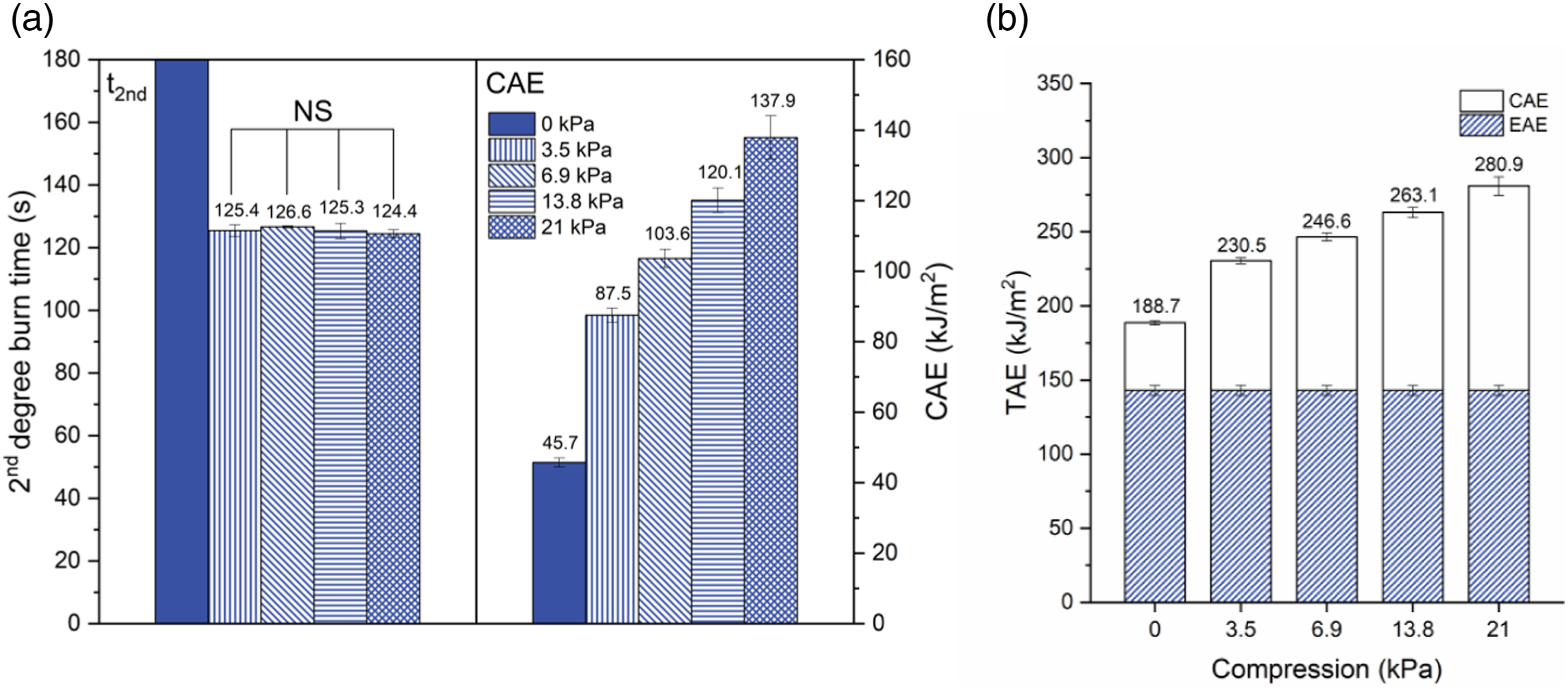
Figure 5(b) shows that the TAE also has a significant increase due to the increasing pressure (p < .05). As compression increases from 0 kPa to 3.5 kPa, the TAE of the fabric system increases by 22.2%, which indicates that compression reduces the OTPP of the fabric system. It is noteworthy that the increasing extent of TAE decreases as the compression continues to increase. When the compression increases from 3.5 kPa to 6.9 kPa, 6.9 kPa to 13.8 kPa, and 13.8 kPa to 21 kPa, the TAE of N1 increases by 7.0%, 6.7%, and 6.8%, respectively. This conclusion was confirmed by the study of Su et al., 9 where thermal protective fabrics exhibited high heat transfer rates under 0.5–3 kPa compression. Additionally, Figure 5(b) shows that the proportion of CAE to EAE increases from 32.0% to 61.2% as the compression increases from 0 kPa to 3.5 kPa, indicating that compression greatly enhances the contribution of stored thermal energy discharge to the total heat gain of the sensor.
Combined effect of air gap and compression
First, to further explore the combined effect of air gap size and compression, an index of α, named the stored thermal energy factor, is introduced to examine the contribution of stored thermal energy to the OTPP, as shown in equation (5).
Figure 6 shows the effect of compression on CAE and α for N1, N2 and N3 with different air gap sizes. Figure 6(a) shows that the CAE increases gradually with increasing compression but decreases with increasing air gap size. The CAE with 21 kPa compression decreases by 58.2% from 137.9 kJ/m2 for N1 to 57.6 kJ/m2 for N3, indicating that the air gap size applied during the exposure can still lower the THP under a forced heat discharge process. This result can be verified by the indicator of α. N3 with an 18 mm air gap size has an α ranging from 0.27 to 0.33, which is significantly lower than the range of N1 (i.e., from 0.38 to 0.49). This decrease in CAE by the large air gap size for a forced heat discharge process should be due to the high temperature gradient between the outer shell and the compressor. Since the air gap size enhances the amount of stored thermal energy within the fabric system during exposure, the temperature of the outer shell at the end of the thermal exposure is increased, resulting in a higher temperature gradient and a greater discharge rate of stored thermal energy to the compressor rather than to the sensor. This result was also corroborated by Su et al.,
9
who suggested that thermal protective clothing with a smaller air gap size should not be compressed even by a low level of compression. Comparison of performance for N1, N2 and N3 with different compression levels: (a) CAE; (b) α (Note: NS = no significant difference was observed at p > .05, otherwise significant differences were determined among different compression (p < .05).
Second, to explore the specific correlations among air gap size, compression level and CAE, regression analyses were conducted for different air gap positions. Their relationships are successfully established by two-dimensional polynomial functions, as shown in equations (6) and (7). The goodness of fit R2 for both regression models is greater than 0.92, indicating that the models fit a set of experimental data well.

Figure 7 shows the relationships between compression, air gap size and CAE for fabric systems with different air gap positions. Regardless of the air gap position, an increase in the air gap size decreased the CAE, and an increase in compression increased the CAE. From equations (6) and (7), it can be found that Relationships between compression, air gap size, and CAE: (a) inner air gap; (b) outer air gap.
Conclusions
This study investigates the effect of air gap size ranging from 0 mm to 18 mm, air gap position and compression on the dual performance of a multilayer fabric system under a low radiant heat source with an intensity of 8.5 kW/m2. For the effects of the air gap size, the results demonstrate that significant impacts of air gap size on the TPP, THP and OTPP are all noted when the size does not exceed 12 mm. Increasing the air gap size not only enhances the TPP by impeding heat transfer from the heat source to the fabric system during exposure but also decreases the THP by reducing heat discharge from the fabric system to the sensor during both natural and forced heat discharge processes. As the air gap size further increases from 12 mm to 18 mm, no significant change is observed for TPP, THP and OTPP.
For the effects of the air gap position, compared to an outer air gap lower than 18 mm, an inner air gap that is next to the innermost surface of the test specimen has a much more positive impact on TPP by impeding heat transfer through the fabric to the sensor during exposure. However, for a natural stored energy discharge process, the THP is more susceptible to being affected by an outer air gap size. Specifically, increasing the outer air gap significantly reduces the CAE discharged from the fabric system to the sensor after exposure, while increasing the inner air gap size does not significantly decrease the CAE. Since the air gap position has this opposite influence in resisting heat transfer during exposure and during natural cooling, the significant impact of the air gap position on the OTPP throughout the test is only observed with a 6 mm air gap size.
For the combined effect of the air gap and compression, regression models were established to explore the relationships among the air gap size, compression and THP for different air gap positions. This demonstrates that increasing compression against the fabric significantly accelerates the discharge of stored energy and advances the occurrence of skin burns. Although the inner air gap contributes more to increasing the TPP during exposure than an outer air gap, it may also bring about severe stored energy discharge under compression. In addition, the results from this study suggest that a larger air gap should be divided into individually separate air gaps within different fabric layers to reduce the heat transfer during exposure as well as lower the stored thermal energy discharge after exposure.
Footnotes
Declaration of conflicting interests
The author(s) declared no potential conflicts of interest with respect to the research, authorship, and/or publication of this article.
Funding
The author(s) disclosed receipt of the following financial support for the research, authorship, and/or publication of this article: This work was supported by the This work was funded by the National Natural Science Foundation of China (No. 51906169), China Postdoctoral Science Foundation (No. 2023M731033), Humanity and Social Science Youth Foundation of Ministry of Education of China (No. 18YJC760021), and Open Project of Zhejiang Provincial Research Center of Clothing Engineering Technology (No. 2021FZKF03).