
Abstract
In order to explore the electromagnetic transmission performance of frequency selective fabrics (FSFs) with fractal units, six samples of Y-shaped fractal parameters with different sizes were prepared by computer embroidery technology, and tested using anechoic chamber test method. The effects of unit type, polarization mode, incident angle and unit size parameters on the transmission performance of different samples were respectively analyzed in depth. The results show that for the aperture type and patch type FSFs, the incident angle has a certain influence. When the incident angle of the two groups of samples is 0°, the resonance peak is the largest. When the incident angle increases to 45°, there are two resonance peaks of different amplitudes in the range of 4 GHz ∼ 20 GHz. The size and spacing of the unit pattern have both visible effects on the transmission coefficient, but the former has a greater impact on the transmission coefficient. There is a certain tension and contraction between the base fabrics during the preparation of the flexible FSFs, which are controlled to make the sample size more accurate. In addition, in order to reduce the calculation time and improve the design efficiency, two kinds of patch type and aperture type with the same size were simulated and optimized using HFSS algorithm. Comparison of measured and simulated results verify the effectiveness of simulation design.
Keywords
Introduction
The frequency selective surface (FSS) is usually composed of multiple identical unit structures arranged periodically in the two-dimensional plane direction. As a traditional spatial filtering structure, FSS can realize the flexible control of electromagnetic waves from the aspects of operating frequency, incident angle and polarization mode. It is a kind of planar or curved electromagnetic device composed of dielectric materials and conductive materials, and the structural unit is repeatedly stacked periodically to form a planar or curved electromagnetic device. It has low-pass, high-pass, band-stop, band-pass and other spatial filtering functions for electromagnetic waves. It has band-pass function, that is, electromagnetic waves of a certain frequency band can pass through, while electromagnetic waves of other frequencies cannot pass through. It is widely used in radomes, antenna sub-reflectors, absorbing materials, electromagnetic shielding,1–7 etc., which bring great application value to military, aviation, communication, and individual protection. According to the transmission characteristics of electromagnetic waves, FSSs can be divided into aperture-type and patch-type.8–10 The processing methods mainly focus on laser engraving, chemical coating, vacuum coating, etc., and traditional FSS products are mostly rigid plates or relatively soft membrane materials. Porous, flexible and lightweight textiles and processing methods are rarely involved.11,12 Therefore, FSF combines FSS and textile materials, emerges as the times require, with both frequency selective characteristics and inherent textile characteristics. 13 In recent years, due to the potential application of its electromagnetic shielding characteristics in the field of civil and military products, it has attracted wide attention of researchers. The emergence of FSFs has filled the gap in the field of FSS products with light weight, softness and low bending stiffness.14,15
The electromagnetic transmission characteristics of FSFs will be affected by many factors, such as the conductivity and size of the array unit, the dielectric parameters of the substrate fabric, etc. And the unit structure type of FSS is very important for the frequency response characteristics of the absorbing material. In addition to some classical structural units, such as ring, square ring, Jerusalem cross, etc., there are many other classical units of the combination of units, such as topological structure, fractal structure, etc. Ben. A. Munk divided the units into centrally connected unit, ring unit, solid unit, combined unit and complex shape unit. 1 Also, Munk proposed the empirical formula for the influence of unit shape and size on the frequency response characteristics. 16 Guan Fuwang analyzed the electromagnetic transmission characteristics of FSFs with cross, Jerusalem, Y-shaped, square units, etc., and used screen printing, computer embroidery, coating printing and other methods to prepare fabric-based FSS samples. 17 The measured results show that the frequency response characteristics of the Jerusalem-shaped and cross-shaped unit fabric-based FSS are more stable to the bending effect, while the frequency response characteristics of the fabric-based FSS of the Y-shaped unit that rotates 90° and does not overlap fluctuate greatly under the same surface state. 17 With the development of nanomaterial manufacturing technology, many researchers have begun to consider applying fractal theory to practical scenarios.18,19 In the early days, many scholars had studied the fractal geometric polarization in antenna design. Due to the self-similarity in fractal theory, the broadband characteristics of the antenna can be successfully realized. In addition, the fractal structure may have a larger perimeter-to-footprint ratio than other shapes, which reduces the number of spaced resonant elements and compact devices, thereby working more efficiently in the restricted region. Liu Juefu et al. 20 studied the cross-shaped fractal absorber of independent metamaterials by using ultra-wideband and polarization numerical methods. The results showed that compared with other structures, the fractal structure can effectively broaden the wavelength band of the metamaterial absorber. The energy around the surface of the multi-layer cross-shaped column and the silicon ring further affects the plasma resonance mode and enhances the absorption of energy. Shi Nannan 21 et al. designed a low-frequency broadband gap seismic metamaterial based on cross fractal column. Through the transient dynamic analysis of El Centro and Taft seismic wave, it was found that the third-order cross fractal seismic metamaterial can reduce the acceleration amplitude of two kinds of seismic surface waves in the band gap frequency range by more than 50%, and has good aseismic isolation performance. Based on the long-term research of different forms of FSS by relevant researchers, some basic laws have been obtained. On this basis, the research and preparation of Y-shaped fractals in this paper have been carried out.
With the progress of science and technology, electromagnetic shielding performance is also widely used in textile and clothing. There are electromagnetic shielding pregnant women's clothing, radiology medical protective clothing and other special professional clothing in the market. Therefore, the electromagnetic shielding textiles have gradually changed from high hardness and poor air permeability to the light, thin, soft, hygroscopic and breathable direction required by civil protective clothing. Based on the above reasons, the preparation process of electromagnetic shielding textiles is particularly important. At present, the preparation methods of FSFs are various, mainly including computer engraving machine cutting sample preparation, screen printing, computer embroidery, coating printing and other processes. The existing FSS products are mostly rigid, while the research of flexible fabric-based FSS, curved FSS and FSF is still rare. Computerized embroidery technology not only retains the performance of the fabric, but also derives novel embroidery with three-dimensional effects. It is widely used in sensors, digital components or electronic devices that can be connected to flat textile products. It has also been successfully used in the fields of manufacturing antennas, coils of unilateral nuclear magnetic resonance systems, etc.22–25 Computer embroidery technology can stack the conductive sewing thread into FSS patterns, and can also form corresponding patterns according to the designed shape and size to produce electromagnetic wave frequency selective transparent textiles. Therefore, FSFs can be prepared by increasing the conductivity of the embroidery yarn and using periodic embroidery patterns.26,27 Noaman Naseer 28 et al. prepared a flexible band-stop FSS array for X-band on jeans substrate by using silver-coated conductive yarn and computer embroidery machine. The results showed that the prototype provides more than 30 dB SE in the X-band and has main absorption behavior for some frequencies in the band. Guan Fuwang 14 et al. prepared several samples with different size parameters by computer embroidery technology, and deeply analyzed the influence of unit type, electromagnetic wave polarization mode, incident angle, unit size parameters and processing methods on different samples. The results confirmed the feasibility of computer embroidery technology. The FSFs prepared by this computer embroidery technology not only retains the softness and air permeability of the fabric, but also enables the conductivity and antibacterial properties of the fabric by weaving the silver-plated yarn. In addition, the computer embroidery process can freely design a variety of flexible and three-dimensional periodic patterns. At the same time, it can also design different FSFs for different electromagnetic wave scenarios according to the frequency selection characteristics of electromagnetic waves, improve the wearability and aesthetics of FSF, and increase the application scenarios of products.
To develop the diversified FSFs, the novel fractal FSFs are designed, prepared and tested in this paper. To deeply study the difference between fractal and non-fractal structures, the non-polarized symmetric Y-shaped units are adopted. Firstly, high-frequency structure simulator (HFSS) modeling and simulation are used to optimize the model parameters. Then, FSF samples are prepared by computer embroidery technology. By adjusting the embroidery parameters, silver-plated conductive yarns are embroidered on the surface of the fabric to form FSFs with periodic conductive patterns. The effects of incident angle, polarization mode and different size parameters on electromagnetic transmission characteristics are systematically explored, and the effectiveness of computer embroidery technology in FSF preparation is analyzed. The research work can provide technical support for the design and preparation of other FSFs, and has reference value for exploring the fractal FSF characteristics.
Experiment
Experimental design
In this paper, the Y-shaped fractal conductive unit is selected for design. The schematics of pore-type and patch-type FSFs are respectively shown in Figure 1(a) and (b), and the conductive units are separately shown in Figure 1(c) and (d). In Figure 1, the conductive units are arranged periodically and the unit period is 20 mm. The sample size is 200 mm × 200 mm. The schematic diagram of Y-shaped FSFs and units.
The size parameters of designed sample.

Simulation design and the establishment of equivalent circuit model
The three-dimensional structures of the patch-type and aperture-type FSS units modeled by HFSS are shown in Figure 2, where the gray part is the Y-shaped fractal silver yarn and the green part is the fabric substrate. The FSS structure adopts a layer of silver yarn patch, and there is a layer of ordinary fabric substrate at the bottom. The patch FSS is woven with silver-plated yarn in the Y-shaped fractal structure, which has conductive function (see Figure 2(a)). On the contrary, the aperture FSS is filled with a layer of silver-coated yarn fabric structure outside the Y-shaped fractal structure, and its internal center is not filled (see Figure 2(b)). Figure 2(a) and (b) show the simulation diagrams of the two FSFs in HFSS, including air cavity, fabric substrate, FSS unit, electromagnetic wave incident and receiving ports. Simulation diagram of two complementary unit models in HFSS.
The fabric substrate is cotton plain cloth, with the thickness of 0.8 mm, and the relative dielectric constant is 1.25. The conductive material is 280 D silver-plated yarn, and the resistivity is 3.55 Ω/cm.
For further simulation, it is necessary to give the corresponding attributes according to the actual object and set the material parameters, such as the conductivity of the Y-shaped fractal silver-plated patch, the dielectric properties (dielectric constant and dielectric loss) of the substrate fabric. At the same time, the port and boundary conditions need to be set manually before HFSS simulation. Figure 3(a) and (b) are the schematic diagrams of the radiation boundary conditions and the electromagnetic wave port setting respectively. HFSS simulation boundary conditions and excitation methods.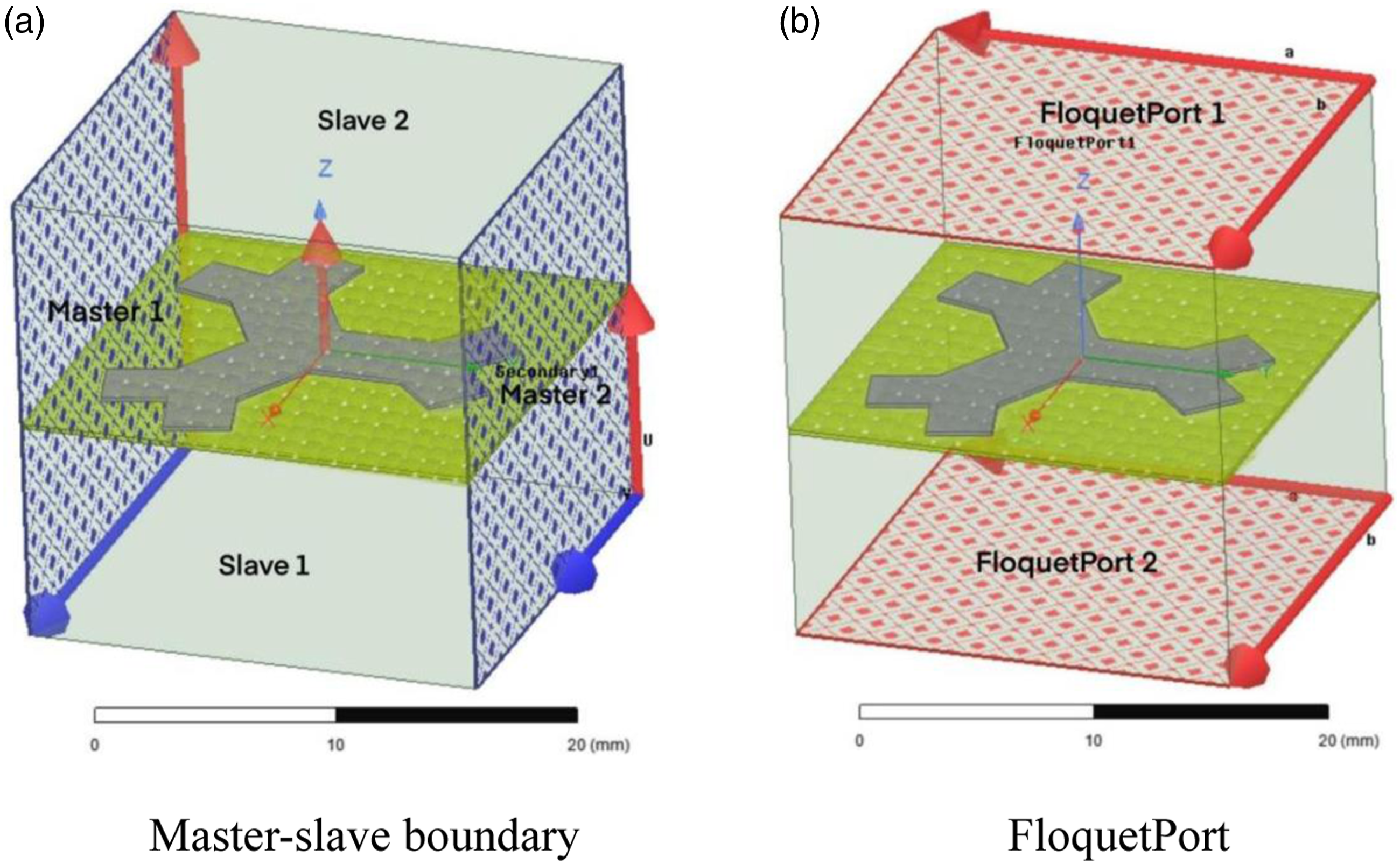
When the conductor interacts with the electromagnetic wave, the electrons on it oscillate and therefore it can be equivalent to an inductance. The two-dimensional periodic array of the patch Y unit can be modeled as a series L-C resonant circuit, while the two-dimensional periodic array of the aperture Y unit can be modeled as a parallel L-C resonant circuit. As shown in Figure 4, where L and C are the inductance and capacitance of the FSS layer. Equivalent circuit diagrams of the two FSFs.
Sample preparation
Types and specifications of relevant equipment and materials.
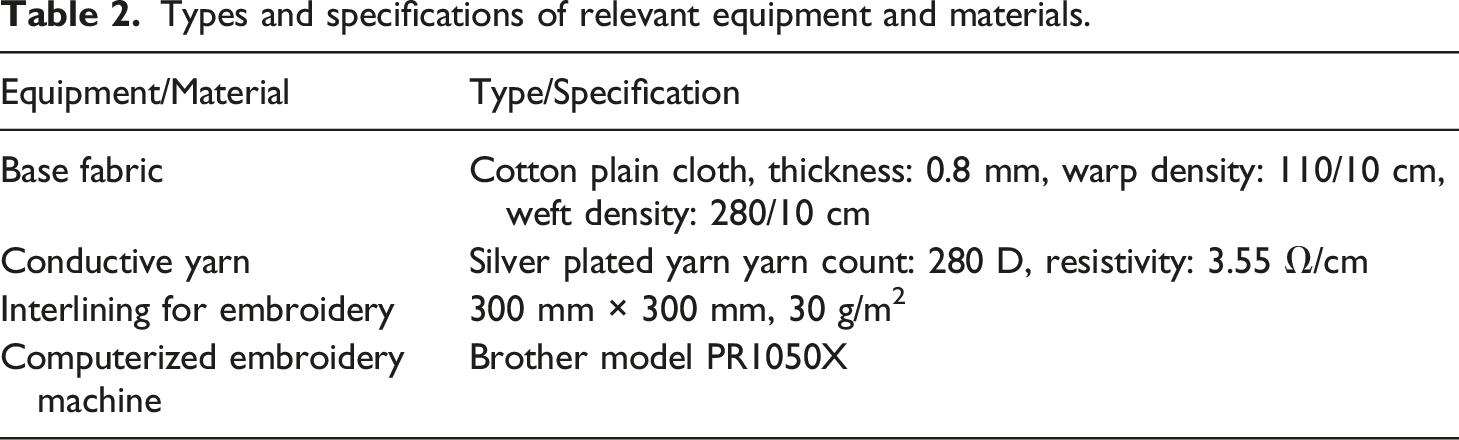
By repeatedly adjusting the operating parameters of the computer embroidery machine, such as the speed of the embroidery needle, the density of the needle, the step distance, etc., samples with relatively smooth units and no obvious shrinkage were prepared and could meet the test requirements. Figure 5(a) shows the sample preparation technology process, Figure 5(b) shows the computer embroidery process, Figure 5(c) and Figure 5(d) respectively show the sample plots of the patch and aperture FSFs. Preparation process and sample photos of patch and aperture Y-shaped FSFs.
Testing procedure
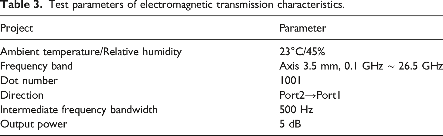
By adjusting the position and angle of the horn antenna and the absorption wall, the free space method can be used to test the electromagnetic transmission characteristics of the sample at different incident angles and polarization modes. The microwave anechoic chamber can reduce the influence of wall and ground electromagnetic signal reflection. These interference signals are absorbed by the sponge absorbing material on the inner wall of the microwave anechoic chamber to shield the interference electromagnetic wave. The electromagnetic environment provided by the microwave anechoic chamber can meet the site test requirements of fabric shielding performance and improve the accuracy of test data. Figure 6 shows the test process of the Y-shaped fractal FSF sample, and Table 3 list the test parameters of electromagnetic transmission characteristics. Test program of electromagnetic transmission characteristics. Test parameters of electromagnetic transmission characteristics.
Analysis and discussion
The main purpose of this paper is to explore the computer embroidery preparation process of Y-shaped fractal FSF, and systematically discuss the influence of different incident angles, polarization modes and different size parameters on the electromagnetic transmission characteristics. In order to cross-validate the effectiveness of the simulation method, HFSS software was used to solve the model of fabric-based FSS, and the rationality of Y-shaped fractal FSF preparation was compared and analyzed more effectively.
Comparative analysis of simulation results
In order to fully verify the characteristics of Y-shaped fractal FSFs, it is necessary to compare and analyze the results of Y-shaped fractal in HFSS modeling with patch type and aperture type to prove that it has good electromagnetic wave frequency selection characteristics. In HFSS, not only the electromagnetic scattering characteristic parameters can be obtained by setting the solution frequency and sweep frequency range, but also the size parameters can be optimized according to the expected resonance frequency point. The 5# and 2# samples are selected to compare the simulation results. In the simulation process, the conductivity of the conductor is 6.3 × 10⁷ s/m (silver) and the thickness is 0.5 mm. The electromagnetic wave is incident vertically. Figure 7 shows the simulation result comparison diagram of the Y-shaped fractal model in HFSS, and the specific data are listed in Table 4. Comparison of simulated and measured transmission coefficient curves. Characteristic indexes of transmission coefficient of 5# and 2# FSFs.

It can be seen from Figure 7 that the simulation results of the fabric-based FSS model are not much different. The bandwidth value of the aperture-type sample is calculated with a threshold of -0.5 dB, while the bandwidth value of the patch-type sample is calculated with a threshold of -10 dB. Taking the patch-type HFSS simulation results as an example, as shown in Table 4, the difference between the main resonance frequency of the two is 0.01 GHz, the secondary resonance frequency is the same, the difference between the main resonance peak is about 1.65 dB and the secondary resonance peak is 0.99 dB. It is completely feasible to use the HFSS model to predict the characteristics of the patch-type fabric-based FSS, which will greatly reduce the calculation time and improve the design efficiency. The simulation results in the software of the aperture-type fabric-based FSS model are also very close. Taking the aperture-type fabric-based FSS model as an example, the resonance frequency difference of the transmission coefficient is about 0.31 GHz, while the resonance peak difference is about 0.31 dB. The two structures of the same size show very close frequency response characteristics under the HFSS algorithm. The results cross-validate the effectiveness of the HFSS simulation design, indicating that the HFSS modeling and simulation algorithm is feasible.
In addition, the patch type (5#) and aperture type (2#) samples with complementary structures were selected to further test their transmission coefficient and reflection coefficient.
Figure 8 shows the comparison of the simulation Analysis of the simulated transmission/reflection coefficient curve.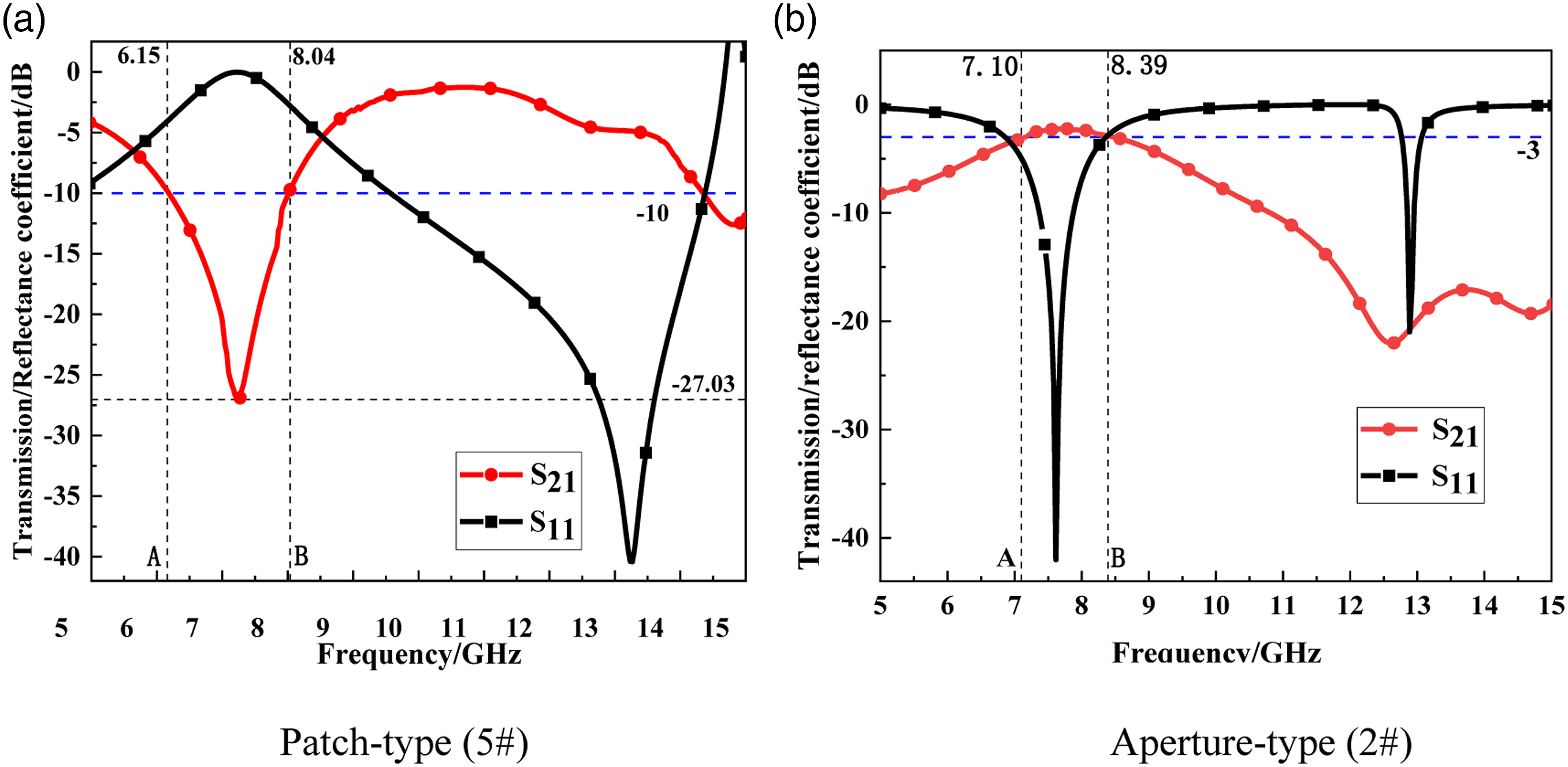
It should be noted that the fractal structure has two resonance frequencies. The reason is that the Y-shaped fractal structure is composed of a larger Y-shaped and a smaller Y-shaped. The interaction between the large pattern and the electromagnetic wave produces the primary resonance phenomenon, while the small pattern produces the secondary resonance under the action of the electromagnetic field.
Influence of unit type
Before analyzing the influence of FSS layer on electromagnetic transmission characteristics, the frequency selection characteristics of two structures are compared and analyzed. We tested the transmission coefficients of aperture type (1#) and patch type (4#) samples in horizontal polarization mode. The incident angle of electromagnetic wave is 0°, and the transmission coefficient curves in horizontal polarization are shown in Figure 9. Comparison of transmission coefficient curves of 1# and 4# sample.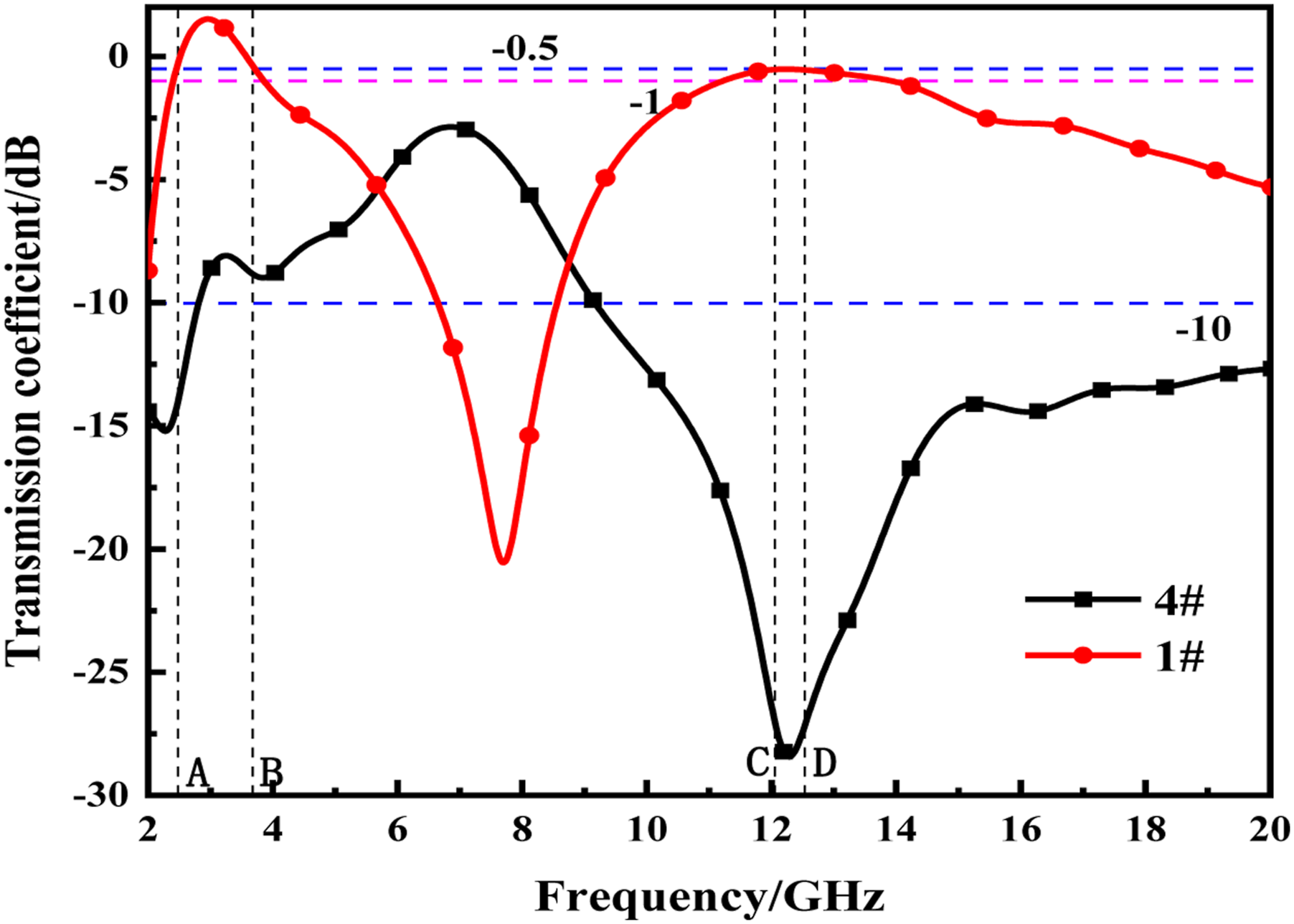
Characteristic indexes of transmission coefficient of 1# and 4# FSFs.

It can be seen from Figure 9 that the transmission coefficient curves of the two complementary FSFs have obvious resonance phenomenon in the test frequency range, but the two curves generally show the opposite trend, and there are two obvious resonance peaks respectively. As shown in Table 5, the main resonance frequency and main resonance peak of the patch-type sample (4#) are 12.29 GHz and -28.55 dB, respectively, while the sub-resonance frequency and sub-resonance peak are 2.28 GHz and -15.27 dB, respectively. The main resonance frequency and main resonance peak of the aperture-type sample (1#) are 12.29 GHz and -0.47 dB, respectively. While the sub-resonance frequency and sub-resonance peak are 2.94 GHz and 1.55 dB, respectively. At -0.5 dB, the main bandwidth and sub-bandwidth of 1# are 0.51 dB and 1.20 dB, respectively. At -10 dB, the main broadband value and the sub-broadband value of 4# are greater than 10 GHz and 0.8 GHz, respectively. In addition, due to that the substrate fabric is not an ideal medium and the inevitable error caused by the processing process, the resonance frequency and bandwidth of the transmission coefficient curve are not exactly the same.
The Y-shaped fractal FSFs have two resonances within the measure frequency range, although the second resonance peak may not be too obvious. The reason is that the Y-shaped fractal structure is composed of a larger Y-shaped unit and a smaller Y-shaped unit. The large pattern interacts with the electromagnetic wave to produce a resonance, and the small pattern produces a secondary resonance under the action of the electromagnetic field. Two resonance effects do not occur at the same time, and therefore the first frequency response and the secondary frequency response appear at different frequency points. The theoretical mechanism is similar when exploring the influences of other factors and it will not be overstated in the following part.
Influence of polarization mode
During the test, there are two electromagnetic wave polarization modes, namely TE polarization and TM polarization. When other conditions are the same, in order to further explore the electromagnetic transmission characteristics of the samples in the two polarization modes, two same patch samples of 3# sample and 4# sample are selected to analyze the characteristic parameters of the transmission coefficient curve. The transmission coefficient of the electromagnetic wave at the incident angle of 0°, vertical polarization and horizontal polarization, the corresponding transmission coefficient curve shows in Figure 10 (a) and (b). Transmission coefficient curves of the FSFs under two polarization modes.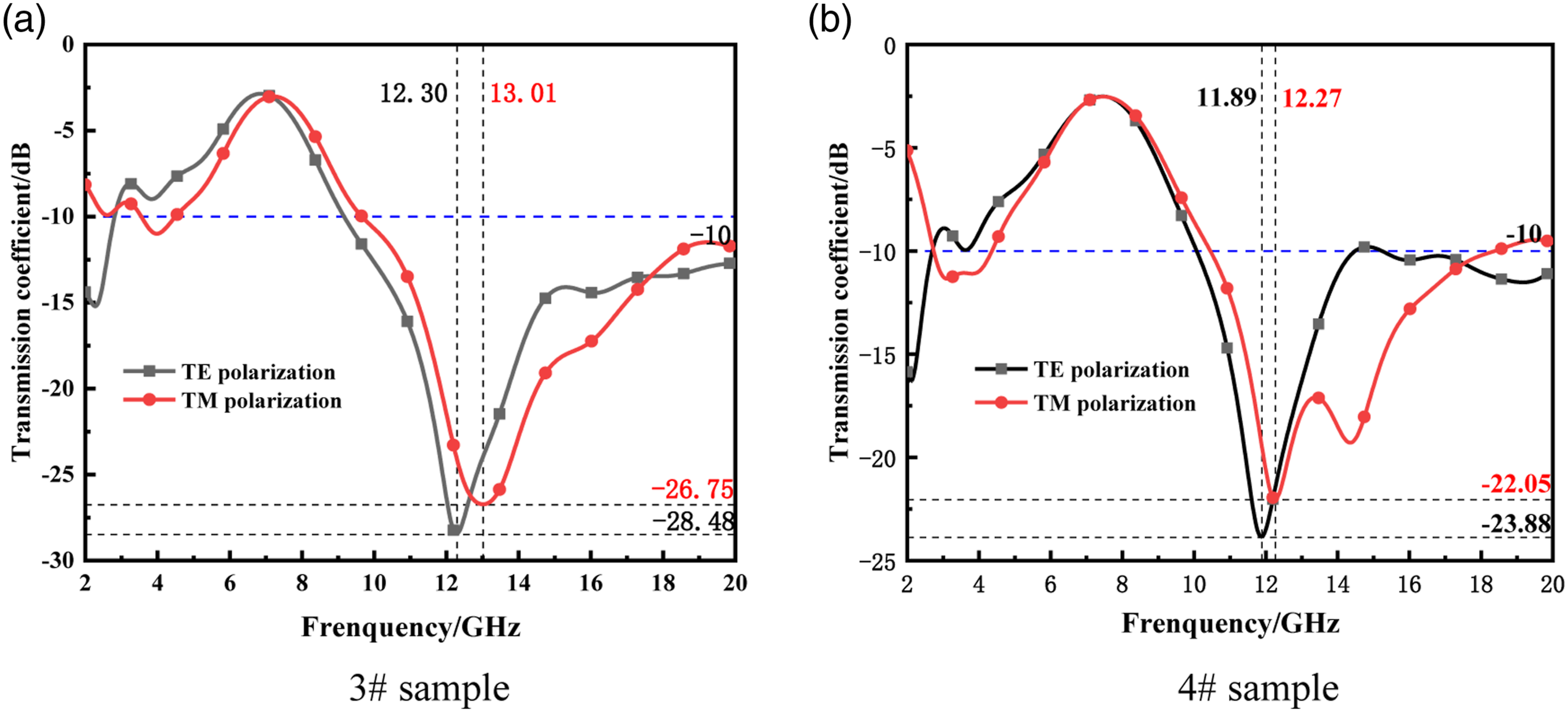
It can be seen from Figure 10 that in the two polarization modes, the transmission coefficient curves of the two groups of samples have obvious resonance phenomenon in the test frequency range, with band-stop characteristics. But the transmission coefficient curve is slightly different. For 3# sample, the resonance frequencies of the transmission coefficient curves are 12.30 GHz and 13.01 GHz, and the resonance peaks are -28.48 dB and -26.75 dB under TE polarization and TM polarization, respectively. Compared with TE polarization mode, the transmission coefficient curve of TM polarization mode moves to high frequency. For 4# sample, the resonance frequencies of the transmission coefficient curve are 11.89 GHz and 12.27 GHz, and the resonance peak are −23.88 dB and −22.05 dB under TE polarization and TM polarization, respectively. The transmission coefficient curve in TM polarization mode also shows a trend of moving to high frequency.
For the same sample, the macroscopic propagation characteristics are basically consistent when the electric field direction is consistent with the relative position of the FSS unit. However, the characteristics of the two polarization modes are not exactly the same, indicating that the combination of the base fabric and the conductive yarn during the preparation of the sample is not completely fitted. This is due to the fluctuation of yarn tension and the slight deformation of the base fabric during the embroidery process. In addition, the environmental value also affects it. Compared with the traditional rigid plate, the flexible FSF is light in weight and easy to bend. There is a certain tension and contraction between the substrates during the preparation process. Therefore, the tension and contraction of the substrate fabric during the computer embroidery process are controlled as much as possible. To a certain extent, the measurement results will be more accurate.
Influence of incident angle
Since the transmission direction of electromagnetic waves is uncertain in reality, which has a certain influence on the frequency response characteristics of FSFs, it is particularly important to explore the influence of the incident angle of electromagnetic waves on the frequency response characteristics. In this paper, the aperture type (2#) and the patch type (5#) are chosen for analysis and the incident angles of the electromagnetic wave are set as 0°, 15°, 30°, 45° and 60° respectively. The transmission coefficient curves of the horizontal polarization are shown in Figure 11 (a) and (b). Transmission coefficient curves under different incident angles.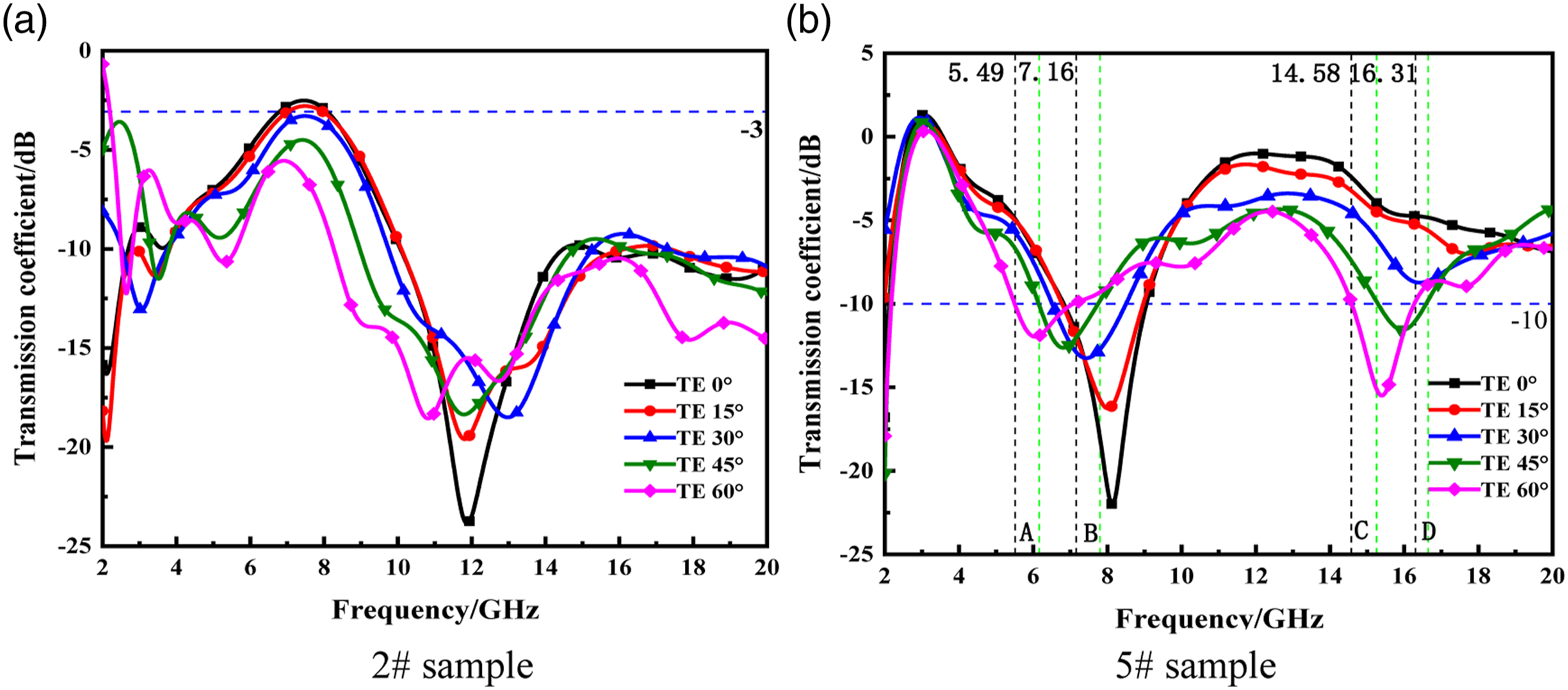
Characteristic index of transmission coefficient of 5# FSF.

From the above analysis, it can be concluded that the incident angle of electromagnetic wave has a great influence on the frequency characteristics of aperture and patch fabric FSFs.
Influence of unit size parameters
The unit size and spacing parameters of FSS roughly determine its frequency response characteristics. Under the same conditions, the aperture type and the patch type are analyzed separately. The unit pattern size is to compare the samples with different pattern sizes and the same pattern spacing. When other conditions remain unchanged, the influence of the size of 3 # and 4 # samples on the transmission characteristics is compared with the unit mode, and the influence of the spacing of 3 # and 6 # samples on the transmission characteristics is compared with the unit mode. When the vertical polarization is 0°, the corresponding transmission curves are shown in Figure 12(a) and (b). Comparison of the influence of unit pattern on the transmission coefficient curves.
As shown in Figure 12(a), for 3# and 4# samples, the resonance frequencies of the transmission coefficient curve are 7.91GHz and 7.12 GHz, while the resonance peaks are −22.34 dB and −22.36 dB, respectively. The results show that from 3# to 4#, with the increase of unit pattern size, the resonance peak increases gradually, and the decrease of the conical resonance peak is unconspicuous. However, the unit patterns size has little effect on the resonance peak. As the unit pattern size increases, the resonance peak appears at the lower frequency. On the whole, the size of the unit pattern has little effect on the FSF frequency response characteristics, and the fluctuation of the transmission coefficient curve is almost the same.
As shown in Figure 12(b), for 3 # and 6 # samples, the resonance frequencies of the transmission coefficient curve are 7.91 GHz and 7.14 GHz, and the resonance peaks are −21.46 dB and −9.65 dB, respectively. The results show as the unit pattern spacing increases, the resonance peak decreases sharply and the transmission coefficient curve fluctuates greatly. On the whole, the transmission coefficient curve of the patch type FSF moves to the left and upward, and the shielding performance of the electromagnetic wave is getting worse. Therefore, the smaller the unit spacing, the better the shielding performance of the electromagnetic wave.
Conclusion
In this paper, the frequency response characteristics of Y-shaped fractal fabric-based FSS are studied from the aspects of preparation method and influencing factors of frequency response characteristics. The following conclusions are obtained: (a) For electromagnetic transmission performance, the influences of various parameters are explored. First, the incident angle has a certain influence on the frequency response characteristics of the two FSFs. Second, the larger the unit pattern size, the greater the resonance peak; the larger the spacing of the unit pattern, the smaller the resonance peak. Third, the polarization mode has little effect on the frequency selectivity of fractal FSFs. (b) Two kinds of patch type and aperture type with the same size is simulated and they show very close frequency response characteristics, which verifies the effectiveness of HFSS simulation process. (c) The computer embroidery technology is used to prepare the FSF samples and the measured results show they indeed have ideal electromagnetic transmission characteristics. In the following work, the accuracy of the sample needs to be further improved, like effectively controlling the stretching and shrinking of the base fabric during the computer embroidery process.
Footnotes
Declaration of conflicting interests
The author(s) declared no potential conflicts of interest with respect to the research, authorship, and/or publication of this article.
Funding
The author(s) disclosed receipt of the following financial support for the research, authorship, and/or publication of this article: This work was supported by the Natural Science Foundation of Fujian Province, China (2023J01906); Innovation and Entrepreneurship Training Project for College Students (S202210399059X, 202310399019X).