
Abstract
Conductive threads are essential for enabling the functionality of e-textiles in sensor applications. However, in this field, there is still a need to study their practical usage, particularly thick embroidered structures. This study investigates the potential of using conductive embroidered structures as sensors and examines how different stitch types can affect the electrical properties of embroidered structures in e-textiles. The paper also explores the application of embroidered structures in twisting and temperature variation, and evaluates their stability when subjected to washing, abrasion and cyclic tension. Three rectangular structures with varying stitch types and geometries were embroidered and tested. The findings highlight the influence of stitch types on electrical properties and demonstrate how washing can affect the different stitch patterns. Furthermore, the structure with the largest jump length can be used in a design suitable for sensing twisting, while all three structures are suitable for detecting temperature variations. This research adds to the development of efficient and long-lasting embroidered electronics textile by providing significant insights for e-textile industrial production.
Introduction
Wearable e-textiles are growing exponentially due to low power needs and constantly developing applications, such as remote physical condition monitoring and preventative healthcare using wearable wireless sensors.1,2 These e-textiles have the ability to sense, react, and adapt to environmental conditions, which makes them a valuable addition to a wide range of applications.3,4 Most wearable e-textiles feature capacitive, resistive, and optical sensors to detect touch and/or measure strain, pressure, temperature, sweat and humidity.5–9 The expected global market for Smart Fabrics is estimated to reach a revised size of US$20.6 Billion by 2030, growing at a CAGR of 21.1% over the analysis period 2022–2030 according to the report. 10
Conductive yarn is the key factor in fabricating these e-textiles, also called smart textiles. 1 The most common type of conductive yarn is metallic. Commercially available metallic yarns can be found in a variety of metals (copper, silver, aluminum, carbon, nickel), and can be twisted or braided to achieve a balance of electrical conductivity, mechanical strength, and flexibility. 11 Among commercially available yarns, silver-coated conductive yarns have also been widely used in wearable e-textiles, since silver is the most conductive metal, it is affordable, and has great antibacterial properties. 12 These polymer-based conductive silver-coated threads are ready for embroidering due to their physical similarity to conventional embroidery threads. Embroidery technique enables the management and integration of yarn with varying electrical characteristics, such as varying resistances, as well as the provision of several other benefits. Furthermore, the ease on the manufacturability of stitched and embroidered structures allows for a mass production of textile sensors without compromising their cost and reproducibility. 13
Electrical properties of embroidered structures with conductive threads depend on numerous parameters, as it was shown by Zheng et al., 14 who conducted an overlay plot analysis to predict the change in the electrical resistance by changing embroidering speed, stitch length, needle thread pre-tension, and embroidering direction. It was observed that the combined output of stitch length and embroidery speed can affect largely the electrical parameters for the fabrication of e-textiles, such as high-performance circuits. Amal et al. 15 conducted an investigation on the operational parameters of embroidery with conductive threads and their effects on communication in antenna applications. They looked at two distinct stitch types (Tatami and Running) and two lengths for each stitch (4 mm and 6 mm). Thread impedance and resistivity were measured using AC voltages at three distinct frequencies: 100 kHz, 1 MHz, and 10 MHz. It was determined that embroidered threads of Tatami type provided excellent results with smaller stitch lengths, acting as a perfect resistor at low frequencies and an inductor at high frequencies.
While looking forward to already published papers and analyzing open literature data about stitch types, 16 stitch length for antennas, 17 transmission lines, 18 electrodes for bioimpedance, 19 which can affect the electrical resistance on the embroidered tracks,20,21 we have been inspired to conduct additional in-depth research for embroidered structures (denser structure), using our previous feasibility study on embroidered conductive lines for I2C communication protocol microcontroller-based wearable electronics. 20 The aims of this study were: to investigate the influence of different stitch types on electrical properties of embroidered structures of the same geometry; to examine the possibility of applying embroidered structures in sensors application for twisting and temperature measurement; to test the stability of the structures under conditions of washing, abrasion and cyclic tension. According to our best knowledge, limited research has been conducted to investigate technological embroidery parameters that may be employed in e-textile industrial production. Therefore, we used an industrial embroidery machine for our investigation.
Materials and methods
Samples preparation
Summary of different commercially available conductive threads.


Technological embroidery parameter
For manufacturing, an industrial embroidery machine was used (Model- JCZA 0109-550, ZSK, Germany). Embroidered line was drawn with length of 150 mm and a width of 4 mm, in stitch digitizing software named as Gis BasePac 10, provided by ZSK, Germany. Cotton fabric was used as a base to embroidered structures. The bottom bobbin thread used throughout the design was bobby Maxi-100, 100% polyester thread, by Gunold Company, Portugal. The reason for using nonconductive thread in the bottom/backside/other side of the fabric is to avoid skin interference with the embroidered design.
Two types of filings were used to embroider the structures: satin and divided satin. Satin fillings are commonly utilized for narrow designs since it provides a smooth embroidery finish achieved with a continuous zig-zag thread no longer than 10 mm. In order to observe the effect of the filling style on the structure, only two parameters – edge type and stitch division – were modified in the digitizing software, while the standard settings were used for all other parameters. The software’s auto-punching mode was employed to automatically fill the shape based on the chosen stitch parameters. It should be noted that when using a technical embroidery machine, various parameters can be adjusted according to the design's specifications, but the stitch type is the most influential one. All stitch types can be filled using either standard or structured settings. The structured settings do not allow the change of the in-fill direction, which was used here to embroider the structure. The process for achieving this is detailed in Figure 1. Finally, twelve specimens were prepared for each structure. Decision making of digitizing software in accordance with the standard settings options available.
Geometry of embroidered structures and stitches
Embroidered structures consisted of two layers. Underlay of structures comprised of a rectangular frame embroidered with the running stitch, and the zig-zag stitch inside the frame, as shown in Figure 2 (green lines). Step length (sl) and step width (sw) of stitches used are given in Table 2. Two different stitches, satin and divided satin, were used for overlay. Two structures, labeled S1-s and S3-s, were embroidered with a satin stitch with different geometrical characteristics, while structure labeled S2-ds was embroidered with divided satin. Geometry of embroidered structures are shown in Figure 2. Jump lengths (jl) and spacings (sp) of satin and divided satin stitches are given in Table 2. Geometry of stitches and images of embroidered structures. Technological embroidery parameters.

Washing and cyclic stretching tests
The washing was carried out in a household washing machine Bosch Maxx 6, according to standard ISO 6330. The samples were placed in small cotton bags and then put into commercial laundry bag. Mixed garment load was 2 kg with washing temperature of 30°C and program duration of 30 min. The spinning cycle speed of the selected wash cycle was 600 r/min. The water hardness in public system of city of Novi Sad is approximately 15 dH (German degrees of hardness) 23 and as such it is characterized as medium hard. It was established that tumble drying leads to more properties changes than washing, 24 therefore the samples were air-dried after being washed. Based on the literature review 24 it was estimated that five washing cycles represent the optimum in terms of energy and resource consumption, which is sufficient to show if there is a change in electrical performances and to what extent.
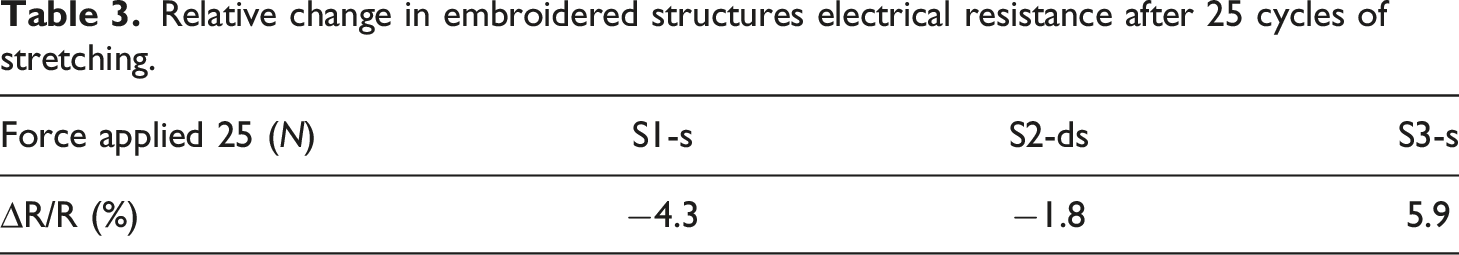
To examine the influence of cyclic stretching on electrical performances, samples were loaded into the tension testing system (34SC-2, INSTRON, Norwood, MA, US) one by one. The sample length between the grips was 10 cm. The maximum force allied during stretching was 25 N. Structures were stretched along the major axis. A measurement of electrical resistance was performed after 25 cycles of stretching and relaxing.
Abrasion test
The Martindale abrasion test was performed using SDL ATLAS Martindale M235 - Abrasion and pilling tester, according to standard ISO 12947 (1–3). Three 30 mm in diameter textile specimens with embroidered structure were tested for each of investigated structures. Abradant material used was worsted wool cloth. A top weight was added to produce constant pressure of 12 kPa between abradant and specimen. Electrical resistance and mass loss was measured after abrasion of 125, 250, 500, 1000, 2000 and, 4000 cycles. Analytical balance KERN ABJ 220–4NM was used.
Electrical resistance measurements
Instruments used in this experiment were PalmSens4, which is an USB and battery powered Potentiostate, Galvanostate, and optional a Frequency Response Analyser (FRA) for Electrochemical Impedance Spectroscopy (EIS). The PalmSens4 has a large potential range (−5 V to 5 V or −10 V to 10 V) and current range (100 pA to 10 mA) with a high resolution and low noise. Connection via Bluetooth guarantees a perfectly floating measurement. The module used for our experiment is the Impedance Spectroscopy Figure 3. (a) Block Diagram for the experimental setup (b) Photos of experimental setup at room temperature, (c) Temperature testing setup, (d) Twisting - 0.05 turns/cm, (e) Twisting - 0.25 turns/cm.
We established stable room temperature during all measurements with a central cooling system and performed experiments in the morning when temperatures are more stable. For measurement of Temperature Dependence of Structures Electrical Resistance, the structures were heated up from one side using a table-top hot plate. Because of the fact the hot plate needs time to reach desired and stable temperature, for each measurement we waited for 5 minutes and checked the temperature of the plate using a thermal camera. After that, we programed a thermal camera to take one image every 5 seconds for 1 minute duration. For each temperature in steps of 5 degrees, we performed a one-minute electrical resistance measurement with PalmSens4. The electrical resistance was measured for a part of the structure 10 cm long, for all samples.
Results and discussion
Electrical resistance of structures at room temperature
The most important parameters affecting the electrical resistance of embroidered structures are the type of thread used, stitch type, its geometry, and the number of stitches. The electrical resistance of the structures at room temperature is shown in Figure 4. All three structures were embroidered with the same commercial thread Silver-tech 100. This study confirmed that the length of the conductive thread used in embroidered structures does not correlate positively with the electrical resistance of structures in general. Structure S3-s demonstrated the highest electrical resistance, although the length of the conductive thread was shorter than in S2-ds and longer than in S1-s. As already mentioned, the number of stitches affects the electrical resistance of embroidered structures. Each time the needle passes through the textile material, the thread conductive layer may be damaged, so an increase in the number of stitches generally contributes to an increase in electrical resistance. The electrical resistance of S2-ds structure with the highest number of stitches was approximately the same as the resistance of S1-s structure having ≈50% fewer stitches. On the other hand, the electrical resistance of S2-ds structure was significantly lower compared to S3-s structure, that had ≈35% fewer stitches. Evidently, the number of stitches is not a decisive factor that determines the electrical resistance of the investigated structures. Electrical resistance of structures at room temperature.
In embroidered structures, the conductive thread parts touch, cross and overlap each other, forming conductive contacts that significantly affect overall electrical resistance. Contact resistance is the electrical resistance that occurs at the contact points when conductive threads are connected. In accordance with Holm theory,
25
contact resistance of multiple contacts spots between conductive threads is given by formula (1), according to the:25–28
The contact force F is directly proportional to the thread tension i.e., stitch tightness. Lowering the tension will influence lowering the contact force, and consequently may affect the contact resistance increase and vice versa. The embroidery machine’s bobbin thread tension and top conductive thread tension were adjusted to ensure a proper stitch formation. Generally, the bobbin tension is set between 22 gf (gram-force) to 24 gf, while the top tension varies depending on the thread used; in this case, it was set at 130 gf for Silver-tech 100. Final tension adjustments were made based on a visual inspection of the seam. The tension was slightly modified when the thread was too loose or pulled to the opposite side of the textile. Although tension remained the same during the embroidery of all three structures, visual inspection showed that the upper layer of the structure S1-s was slightly looser compared to S2-ds and S3-s, as could be seen in Figure 2. There is a simple rule of sewing and machine embroidery – the less thread used for a stitch, the tighter the stitch. The stitch type used and geometry with the highest jump length obviously loosened the stitch of S1-s. On the other hand, divided satin stitch in structure S2-ds caused higher contact force than S3-s due to the shortest jump length.
Based on the geometry of the structures shown in Figure 2; and Table 1 it is clear that the number of contacts between threads underlay and upper layer in structures S2-ds and S3-s was approximately the same, while in structure S1-s was significantly higher. Contacts also existed within an upper layer. The number of contacts within upper layer of structures S2-ds and S3-s was comparable in terms of geometry. As for structure S1-s, looser stitch and larger jump length gave the possibility for the thread to be placed one over the other in the upper layer, thereby increasing the number of contacts. Therefore, the number of contacts in the upper layer of structure S1-s could be comparable to structures S2-ds and S3-s.
A total number of contacts in structure S1-s was significantly higher, but the contact force was slightly lower than in the other two structures. Given that the electrical resistance of structure S1-s was the lowest, it can be concluded that the number of contacts was the main factor determining its electrical resistance. Otherwise, when comparing structures S2-ds and S3-s, with similar number of contacts, structure S3-s had a higher electrical resistance due to a lower contact force.
Temperature dependence of structures electrical resistance
Figure 5 shows the relative change in embroidered structures electrical resistance during external heating. The electrical resistance decreased with increasing temperature and experimental results obey linear dependence for all embroidered structures. It is well known that electrical resistance of the conductors increases with an increase in temperature. According to our experimental results, it was diametrically opposite. This behavior must be affected by the intrinsic characteristics of the thread and changes in contact resistance.
29
In order to examine the extent to which the aforementioned affected this behavior, the influence of contact between threads was eliminated. Hence, electrical resistance temperature dependence was measured for the thread and for the zig-zag stitch embroidery (sl=4mm , sw=2mm). This procedure allowed us to examine the influence of the thread only on the change in electrical resistance with the change in temperature. The results of these measurements are shown in Figure 6. Temperature dependence of relative change in embroidered structures electrical resistance. Temperature dependence of relative change in electrical resistance of Silver-tech thread and its zig-zag stitch.

A trend with negative temperature coefficient (NTC) was established for all structures (S1-s, S2-ds and S3-s). Observed NTC of the thread contradicted to the fact that the electrical resistance of the conducting material increased with the temperature increase. NTC phenomenon of conductive threads has not been thoroughly investigated and explained. Some papers explained NTC of conductive threads by its conductive multifilament structures.29,30 In case of single-filament thread, or thread with only one conductive filament, the electrical resistance increased with the increase in structure.31,32 Given that the thread used for embroidery was multifilament, plied of conductive filaments, there was most likely a microscopic thermal expansion of filaments under the influence of temperature increase. In that case the filaments fit better, and the resistance of the thread decreases due to the reduction of contact resistance between filaments.
Relative resistance change rate per degree Celsius i.e., slope of linear function, for Silver-tech 100 and zig-zag stitch, was lower than in embroidered structures S1-s, S2-ds and S3-s. In other words, the electrical resistance of the embroidered structures decreased faster with increasing temperature if compared to the thread and simple zig-zag stitch. This fact indicates that the contact resistance of the structures affected the rate of electrical resistance change. An increase in temperature might have caused the decrease of contact force between underlay and upper layer and, consequently, an increase in contact resistance. On the other hand, a temperature increase also caused an increase of the contact force within the upper layer, resulting in the decrease of contact resistance. According to results obtained, the latter affects the NTC behavior more.
Twisting analysis
One of the relevant characteristics of flexible electronic is its behavior during twisting. In some applications, the insensitivity to twisting is required, i.e., ability of structures to withstand twisting without significant change in resistance, and vice versa when they are used for twisting sensors and measurements. We performed twisting analysis to describe the prepared structures and investigate whether and to what extent stitch type division and geometry influence sensitivity to twisting. Samples gauge length was 10 cm while measuring resistance during twisting. Initial experiment showed that the change in resistance during twisting (for 0.05 turns/cm, 0.1 turns/cm and 0.15 turns/cm) were insignificant for S2-ds and S3-s, while structure S1-s showed the decrease in relative resistance change with twisting angle increase. Therefore, an additional measurement with expanded twisting angle interval for S1-s structure only was conducted, and results are shown in Figure 7. Twisting to the side with conductive thread on a surface was named clockwise, while twisting to the opposite side with nonconductive thread on a surface was named counterclockwise. Diametrically different results were expected for different twisting directions as it was reported in.
33
Cheng et al. reported an increase of relative resistance changes for counterclockwise twisting of graphene-based fiber structure, and vice versa for clockwise direction.
33
Investigated structure S1-s showed a relative resistance decrease for both twisting direction, slope of fitted linear function was approximately the same for both directions. Relative change in electrical resistance of S1-s structure during twisting.
Twisting counterclockwise resulted in contact point increase, and contact force increase. This would result in a contact resistance decrease and consequently with S1-s structure resistance decrease. However, the same happened for clockwise twisting. Possible explanation for this behavior could be the fact that a part of conductive thread was pulled through textile to a bottom side. The picture depicting the setup of the twisting experiment shows that the structure was stretched between two supports. Consequently, the structure was under tension during the measurement to a certain extent. Tension was applied to prevent joining the side edges of the structure. The degree of tension increased with the increase in the twisting angle. Therefore, identical trend found during twisting structure S1-s in two different directions is a consequence of simultaneous twisting and tensioning that could not have been avoided.
The detected behavior of S1-s structure, with the highest jump length, indicated that this structure could be used as a sensor for twisting as well as for a twisting angle measurement. The other two investigated structures, S2-ds and S3-s, with lower jump length, were insensitive to twisting.
Washing and cyclic stretching tests
An important feature of textile electronics is their ability to withstand washing. The details concerning washing are given in Materials and Methods section. Although some studies indicated that inserting e-textiles inside a washing bag can increase the ability to withstand washing,34,35 samples were placed into small cotton bags to avoid samples friction against the rigid washing bag.
The electrical resistance of all structures increased after five washing cycles, as can be seen in Figure 8. Changes in electrical properties after washing can be the result of several combined factors, main of them are abrasion of conductive thread, textile shrinkage and impurities that have accumulated in the washing machine during its previous use.24,36,37 The impurity influence was significantly reduced by the fact that the samples were firstly packed into small cotton bags and then placed into commercial washing bag. Electrical properties can also be affected by chemicals present in laundry detergents and fabric softeners. This was not the case in our study, considering that detergents and fabric softeners were not used during washing, thus the influence of chemicals on the electrical properties during washing was reduced to a minimum. Electrical resistance of the structures at room temperature before and after five washing cycles.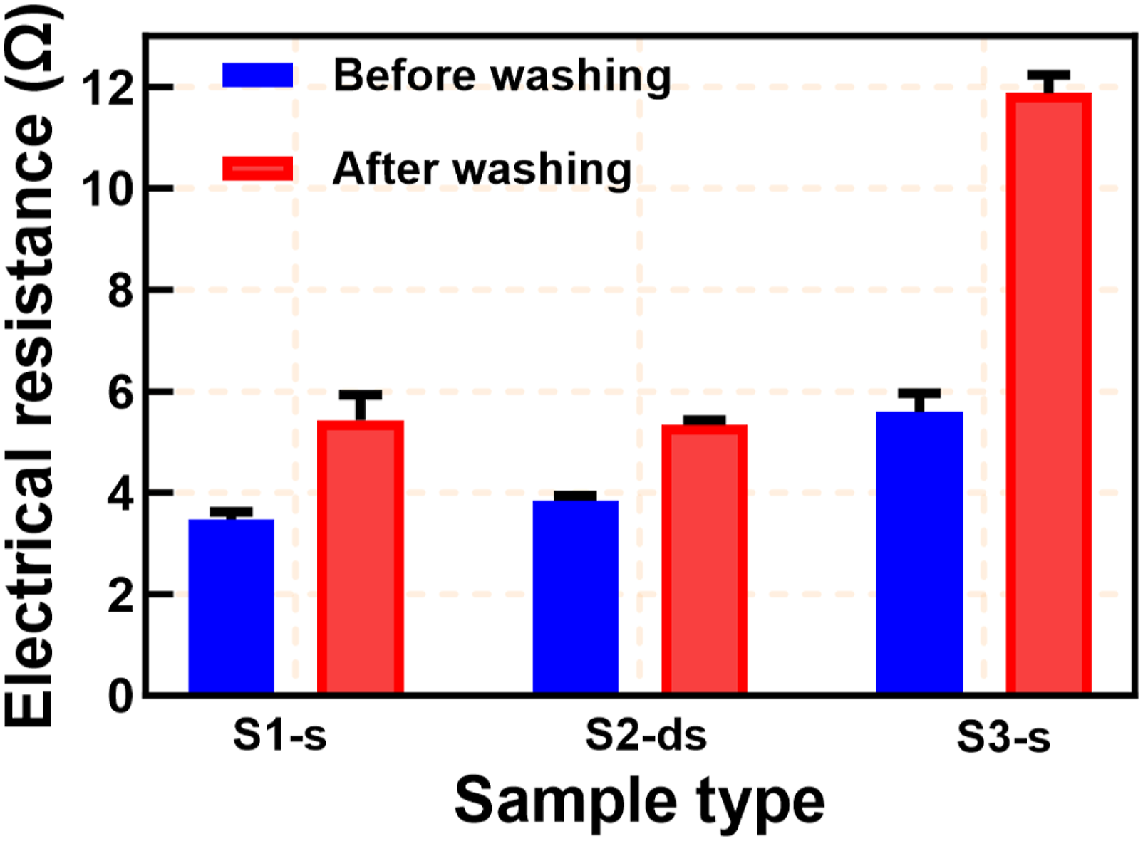
Embroidered structures were exposed to centrifugal, frictional and impact forces during washing, which can lead to thread conductive layer wear off. An abrasion could be observed under scanning electron microscopy (SEM) micrographs. SEM images and EDX analysis results are given in Figures 9 and 10, respectively. SEM analysis showed no significant structural and surface morphology differences between unwashed and washed samples. Considering both SEM and EDX results, it is evident that washing reduced the percentage of silver coating, while all the elements used in core, such as silicon (Si), tin (Sn), and carbon (C) were still present in the same percentage. Stavrakis et al. reported results of washing degradation of commercial conductive threads properties. An increase in electrical resistance of ≈17% was reported for conductive thread Silver tech-100 after five cycles of washing.
38
Relative resistance change in this study was significantly higher for all three structures: 56% for S1-s, 39% for S2-ds and 112% for S3-s. The S2-ds structure with the smallest jump length showed the smallest change in electrical resistance. This result could be explained by the fact that satin stitches with smaller jump lengths are less susceptible to abrasion during washing in general. In accordance to that, it was expected that resistance of the structure with the largest jump length (S1-s) would be changed the most after washing. However, it was not the case. The upper layer in investigated structures was certainly more exposed to wear. The contacts between the underlay and upper layer were shielded and their abrasion did not occur during washing. This is in accordance with findings that multiple embroidered layers on top of one another enhance the washability.39,40 As already mentioned, number of contacts in structure S1-s was the highest and had the greatest impact on the electrical resistance of this structure. Therefore, contrary to expectations, the electrical resistance of S1-s did not change the most. Considering all previously mentioned, it can be concluded that abrasion was not the main cause for changes. SEM images of embroidered structures (a) before and (b) after five washing cycles. EDX analysis results for embroidered structures (a) before and (b) after five washing cycles.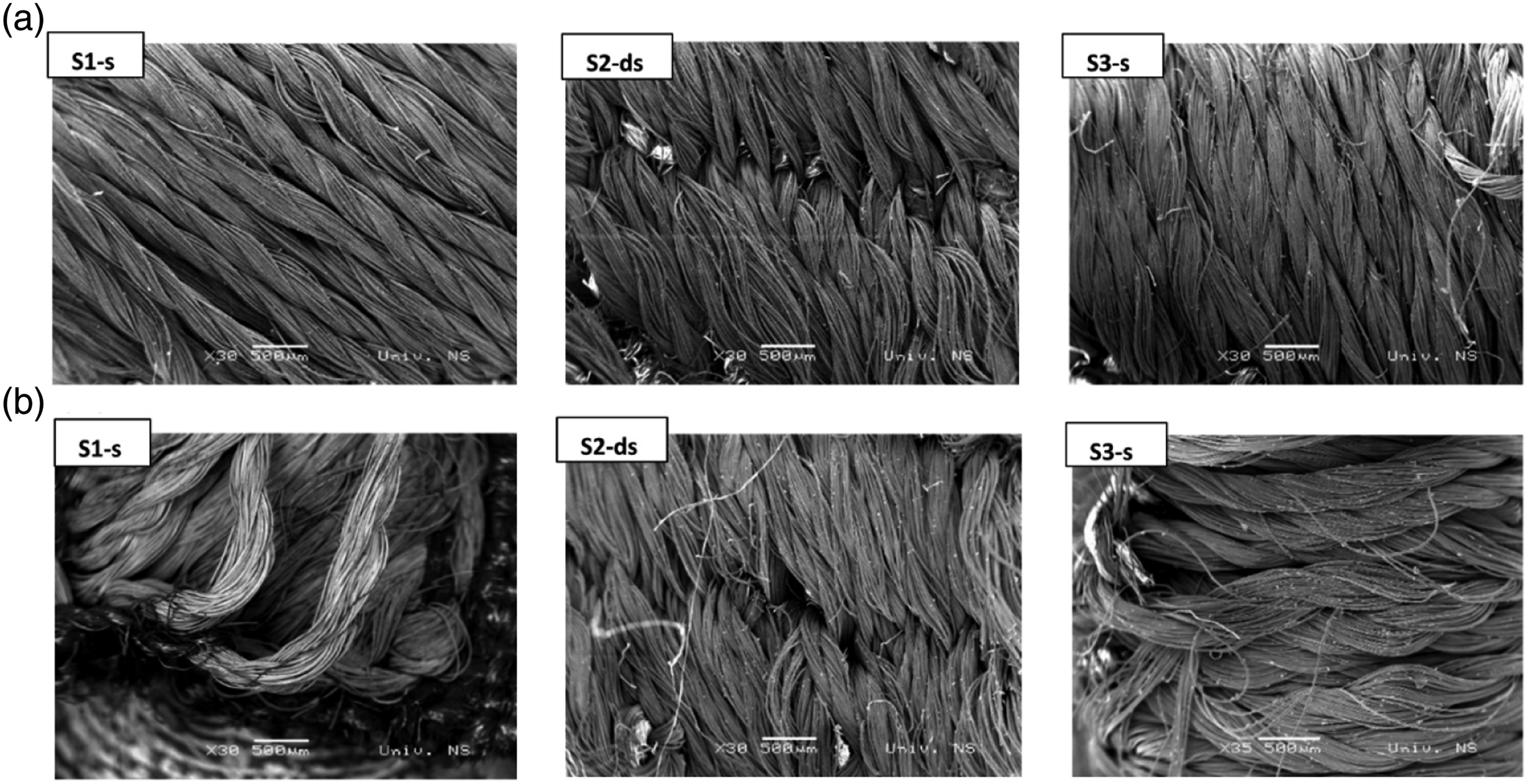

When considering the washability of e-textiles as a whole, the coalition of the conductive thread with the textile should be taken into account, i.e., the effect of washing on the textile. The electrical properties of embroidered structures are also affected by the shrinkage of fabrics during washing.41,42 Cotton fabric used had not been washed prior to embroidery. First washing cycles can cause shrinkage of cotton, especially if it is washed in hot water. Washing in cold water also leads to a certain amount of shrinkage. Even a small shrinkage of the fabric can cause a decrease in the contact force between threads and an increase in the contact resistance. Previously mentioned has clearly happened, considering that in the SEM photographs of all three structures (Figure 9) it is evident that the threads were less tight after washing.
It was concluded that the change in the electrical resistance of the structures can be attributed to the combined influence of conductive thread abrasion and shrinkage of the cotton fabric during washing. The variation in electrical resistance due to washing was significantly higher for embroidered structures compared to the change determined for the conductive thread itself. It was found that the ability to withstand washing depended on stitch type and its geometry. Structure embroidered with divided satin stitch was the least susceptible to washing due to the smallest jump length. The obtained results indicated that embroidery done with small jump length in a way that allows for maximum contact between conductive threads will withstand washing better. Nevertheless, the best way to keep consistence during long-term use of the e-textile is to cover the conductive part with non-conductive threads. This way the conducive thread will be certainly less damaged and changed.
Relative change in embroidered structures electrical resistance after 25 cycles of stretching.
Abrasion test
Abrasion resistance is the facility of a fabric to resist surface wear caused by rubbing with another material. It is used for evaluating the durability of textile materials in use i.e., lifespan. Changes on the surface caused by abrasion can be reflected in changes of physical properties, for instance: reflectance factor and color change 43 liquid transport phenomena in the porous systems, 9 electrical resistance 12 etc.
The results of the Martindale abrasion method are presented in the paper. Martindale method performs to measure flat abrasion resistance of a textile, edge abrasion, or other types of wear that may occur are not considered. Structures wear was done with wool fabric by monitoring the changes in mass and electrical resistance at different numbers of cycles. The loss of conductive thread silver plating was evident by visual comparison as could be seen from photos taken after a certain number of cycles (Figure 11). Photos of embroidered structures at different stages of abrasion test.
It was observed that by increasing the number of wear cycles, the electrical resistance increased for all three structures as could be seen in Figure 12. The highest relative resistance change was found for the structure S3-s. These increases are mainly caused by the stripping of the conductive coating. Breakages of the conductive fibers could also cause an increase in resistance, but the tearing of conductive fibers due to abrasion did not occur (see Figure 11). Relative change in electrical resistance of embroidered structures during abrasion.
It was found that the mass of all samples decreases with increasing number of wear cycles. The relative mass loss is shown in the supplemental material in the Figure S1. The relative mass loss after 4000 cycles was the largest for structure S3-s (≈0.5%) and the smallest for S2-ds (≈0.2%). This agrees with the fact that the change in electrical resistance was the largest for structure S3-s and the smallest for S2-ds. In this way, it was determined that the S2-ds structure is the most resistant to wear. High abrasion resistance, followed by other specific features is preferable for e-textile.
Conclusion
Limited research has been conducted on exploring the technological embroidery parameters applicable to industrial production of e-textiles. Thus, this research article aimed to fill this gap by investigating the influence of various stitch types on electrical properties of embroidered structures. Three conductive two layered structures, embroidered using an industrial embroidery machine, were examined. A commercial conductive thread Silver-tech 100 was used for embroidery. Structures of the same rectangular shape, length of 150 mm and a width of 4 mm, differed in terms of stitch types (satin and divided satin) and stitch geometries (jump length and spacing).
The results indicated that variations in stitch types and geometry influenced the electrical properties of the embroidered structures, primarily due to differences in contact resistance that depends on contact points and contact force. The lowest resistivity found for satin stitch structure S1-s with the largest upper layer jump length. Given that a total number of contacts between thread parts in structure S1-s was significantly higher, but the contact force was slightly lower than in the other two structures, it was concluded that the number of contacts predominantly determined electrical resistance.
The study examined the feasibility of utilizing embroidered structures in sensor applications for measuring twisting and temperature. All investigated structures proved to be suitable for temperature measurement applications. In terms of twisting, the structure S1-s with the largest jump length was found to be applicable for twisting angle measurement. Other investigated structures, with smaller jump length, found insensitive to twisting.
Structures stability was tested after washing, abrasion and cyclic tension. The washing tests revealed that different stitch geometries responded dissimilarly to the same washing procedure. The same was found after cyclic tension and abrasion. Structure S2-ds was found the least sensitive to washing, cyclic stretching, as well as to abrasion.
Overall, this research sheds light on the importance of considering technological embroidery parameters in the industrial production of e-textiles. The findings contribute to the understanding of how different stitch types and geometries can impact the electrical properties of embroidered structures. As further research is conducted, the field of e-textiles can benefit from these insights to enhance the design and production of functional and durable embroidered electronic textiles. Limitations of this study can be summarized as follows: the investigated structures were embroidered only on cotton fabric, the lifespan and durability of e-textiles depend, to some extent, on the type of fabric used; the ambient temperature during all measurements was kept constant by means of a central air conditioner the next step will be repeating the temperature dependence test inside the laboratory oven where we can keep the same environmental temperature; the influence of ambient conditions on the change in electrical resistance during twisting was not examined it was measured only at room temperature.
Supplemental Material
Supplemental Material - Influence of stitch type division and geometry on the electrical properties of conductive embroidered structures
Supplemental Material for Influence of stitch type division and geometry on the electrical properties of conductive embroidered structures by Hima Zafar, Milica V Vasić, Željko Popović, Kalman Babković and Goran M Stojanović in Journal of Industrial Textiles
Footnotes
Declaration of conflicting interests
The author(s) declared no potential conflicts of interest with respect to the research, authorship, and/or publication of this article.
Funding
The author(s) disclosed receipt of the following financial support for the research, authorship, and/or publication of this article: This research was funded through the European Union’s Horizon 2020 research and innovation programme under grant agreement No. 854194.
Correction (November 2023):
This article has been updated with minor grammatical or style corrections since its original publication.
Supplemental Material
Supplemental material for this article is available online.
References
Supplementary Material
Please find the following supplemental material available below.
For Open Access articles published under a Creative Commons License, all supplemental material carries the same license as the article it is associated with.
For non-Open Access articles published, all supplemental material carries a non-exclusive license, and permission requests for re-use of supplemental material or any part of supplemental material shall be sent directly to the copyright owner as specified in the copyright notice associated with the article.