
Abstract
To address the issue of non-uniform fiber volume fraction between layers in the compression compaction process of C/C soft-hard mixed preforms, a multi-unit variable duration cyclic compression compaction process based on the inter-laminar fiber compression viscoelastic deformation behavior is proposed. This process aims to gradually eliminate the rebound characteristics of inter-laminar fibers and reduce the error of inter-laminar fiber volume fraction. The mapping relationships between the number of units, holding duration, and compaction times with the rebound height of inter-laminar fibers are established using data fitting. The compression compaction process is determined using the Box Behnken response surface design method, and digital devices are utilized for preform compaction experiments. The micro-morphology of the preform is observed using an optical microscope, and the density of inter-laminar fibers before and after process optimization is compared. Experimental results indicate that when the number of units is 3, the holding duration is 57 s, and the compaction times is 2, the fiber volume fraction of the soft-hard mixed preform is 42.90%, which is 12.16% higher than before process optimization, and the error of inter-laminar fiber volume fraction is less than 6.5%.
Keywords
Introduction
C/C composites are widely used in the aerospace industry due to their low density, high strength, and excellent thermal shock resistance, among other advantages. Among the different types of C/C composites, the soft-hard mixed C/C composite is regarded as an ideal anti-erosion material due to its integral mechanical properties. The fiber layers are oriented perpendicular to the direction of airflow erosion, making this composite material particularly suitable for high-pressure and high-temperature environments. It is considered an ideal material for solid rocket motor throats. 1 The preform used in this study was prepared using a soft-hard mixing molding method that involved mixing carbon fibers with carbon fiber rigid rods (hereafter referred to as carbon rods). The carbon rods were arranged in a regular triangular equidistant pattern perpendicular to the horizontal plane, and the fibers were stacked in three directions between the carbon rods. The preform was then compressed using a vertical compression load to achieve the desired fiber volume fraction. During the compression compaction process, the bending and cross-section deformation of carbon fibers between the carbon rods resulted in changes to the internal structure of the preform, which in turn affected the fiber volume fraction and ultimately influenced the mechanical properties of the composites.2,3
Currently, both domestic and foreign scholars have conducted relevant research on controlling the fiber volume fraction in composite material preforms formed by compression. The most common method for this is conducting fabric compression deformation experiments using a universal testing machine. Hu et al. 4 utilized experimental methods to record and analyze the interaction between compressive load and compaction displacement on forming process parameters during the compaction process of three-dimensional orthogonal fabrics. They established the mapping relationship between the compaction load and the displacement in the thickness direction of the preform through the method of fitting the experimental data. Wei et al. 5 have conducted compression molding experiments on carbon fiber and glass fiber fabrics under two working conditions and have analyzed the viscoelastic curves and viscoelastic model parameters in the compression, stress relaxation, and springback stages using viscoelastic theory. The fabric compression experiment demonstrated that the fabric compression process could be divided into three stages: compression, rebound, and retention. Specifically, the fabric is compressed to a certain fiber volume fraction under a compressive load. Due to the viscoelastic properties of the fibers, they will rebound when the compression load is released, resulting in a decrease in the fiber volume fraction of the fabric during this stage. During the holding stage, pressure retention or changing the viscous medium between fibers can reduce fabric rebound and increase fiber volume fraction.
To investigate the compaction characteristics of preforms, scholars have established mathematical models to more accurately reflect the compression compaction of preforms and simulate their compression deformation behavior, which is of great significance for the calculation of composite permeability, thermal conductivity, and mechanical properties. To model the macroscopic behavior of fabrics, commonly used models such as the Maxwell model, composed of springs and sticky pots, are used to characterize the viscoelastic behavior of preforms during compression deformation. Kim et al. 6 have demonstrated that connecting five Maxwell models in parallel can effectively predict stress changes of glass fiber plain woven fabrics and random felt during the relaxation stage. Also, Kelly et al. 7 have employed a spring to parallel n Maxwell elements to better characterize the stress evolution of the preform during the compression and relaxation stages Moreover, Somashekar et al. 8 successfully predicted the stress changes of four different structural fabrics during the relaxation stage by connecting a spring in parallel with two Maxwell units. Liu et al. 9 represented the viscoelastic behavior of plain woven fabrics using stress relaxation modulus and time-varying plate stiffness matrix and verified the accuracy of this model. Furthermore, this method was extended and applied to both two-dimensional (2D) fabrics (plain and twill) and three-dimensional orthogonal fabrics, with the aim of studying the effects of different weaving methods on the viscoelastic behavior of fabrics. Jiang et al. 10 brought about an analysis of the cross-sectional changes of fiber under load, and based on the classical constitutive relationship of fiber, proposed a theoretical model to establish the correspondence between the compression thickness of two-layer unidirectional fabrics and the external load and inter-laminar offset in arbitrary nested states. What is more, the model was extended to predict the compression response characteristics of multi-layer fabrics. In the micro-scale modeling of fabrics, Wang et al. 11 developed a micro-computing tool based on the explicit digital element method. The tool digitizes and discretizes each fiber into multiple short rod elements connected to a set of frictionless nodes. Upon calculations, contact points between fibers under compression load are detected, and the compression force and friction force between fibers are determined based on the contact stiffness and friction coefficient. Finally, the node displacement is determined through the program. As computer technology continues to progress, this method shows promising potential for simulating the mechanical behavior of fabrics in greater detail. Daelemans 12 proposed a fiber model based on truss elements, which does not consider bending stiffness, to construct the micro-geometric shape of three-dimensional fabrics. The yarns with circular cross-sections are composed of virtual fibers that are arranged in an ideal loose manner. The compaction process of the fabric is handled using the general algorithm of ABAQUS software to address the contact between fibers. The establishment of the aforementioned microscopic model allows for a more realistic reflection of the internal structure and deformation of the preform under load.
In the pursuit of improving the fiber volume fraction of preform, Liu et al. 13 utilized experimental methods to characterize the geometric and micro-structural features of the preform fibers. Through analysis of these characteristics, the impact of macroscopic compaction densification on the preform’s micro-structure was determined. Results indicated that the cross-sectional morphology of fibers with high fiber volume fractions tended to be more rectangular under varying compaction loads, thus providing valuable insights for the prediction of composite material performance. Li et al. 14 put forward a novel algorithm for enhancing the fiber volume fraction in the reconstruction model of short cut fiber reinforced composites with large aspect ratios. This algorithm enables the pre-design and control of fiber orientation and length distribution in the reconstruction model, resulting in a significant increase in fiber volume fraction in the range of 50∼200 fiber aspect ratio. On the other hand, Shan et al. 15 devised a variable pressure vibration cyclic loading compaction process based on the fiber layer’s compression deformation behavior. The process can progressively eliminate the fiber layer’s rebound properties, reduce the degree of fiber damage during compaction, maintain preform dimensional stability, and enhance the preform’s fiber volume fraction.
Despite the fact that numerous scholars, both domestic and foreign, have established corresponding theoretical and numerical models, and conducted a significant amount of compression experiments on the compression forming mechanism of preform, there remains a dearth of research on eliminating the rebound characteristics of preform fibers, improving the fiber volume fraction, and reducing inter-laminar density errors. Consequently, this study proposes a multi-units variable duration cyclic compression compaction process, based on the inter-laminar compression viscoelastic deformation behavior of fibers, aimed at gradually eliminating fiber rebound characteristics, and improving the compactness and inter-laminar uniformity of the preform. To verify the reliability of the process, a digital device was utilized to conduct preform compaction experiments. Moreover, optical microscopy was employed to observe the micro-morphology of the preform that was compacted by the optimized process before and after, and to compare the density of inter-laminar fibers.
The moulding process of soft-hard mixed preform
The carbon rods in the soft-hard mixed preform are arranged perpendicular to the carbon fibers according to the required regular triangle equidistant arrangement, the diameter of the carbon rod is 1.2 mm, and the distance between any two adjacent carbon rods is not more than twice the diameter of the carbon rod. The carbon fibers are laid in a three-way stacked horizontal layer at 0°, 120°, and 240° angles between the carbon rods, as illustrated in Figure 1(a)–(c) The moulding process of soft-hard mixed preform. (a) The laying of fiber 0°. (b) The laying of fiber 120°. (c) The laying of fiber 240°. (d) Unit or multi-units compression compaction. (e) Load release. (f) The forming of preform.
The C/C soft-hard mixed preform adopts the unit compression compaction process presently, which is “laying one unit and compacting one time without holding duration” and the layers fibers bounce back after the load is released. However, as the height of the laid fibers increases, the rebound height of the bottom fibers decreases or does not occur due to repeated compression loads. Conversely, the rebound height of the upper fibers is higher than that of the middle and bottom fibers due to fewer loading times. Therefore, there is a significant error in the fiber volume fraction in the upper, middle, and bottom parts of the final formed preform, namely, ρbottom > ρmiddle > ρtop, as depicted in Figure 1(f).
Thus, based on the unit compression compaction process, the compression compaction process of a multi-units variable duration cyclic is propose to eliminate the rebound characteristics of inter-laminar fibers gradually, to improve the fiber volume fraction of preform and the consistency of inter-laminar density. The experimental method of a multi-units variable duration cyclic compression compaction process is explored as follows.
Research on the compaction behaviour of soft-hard mixed preform
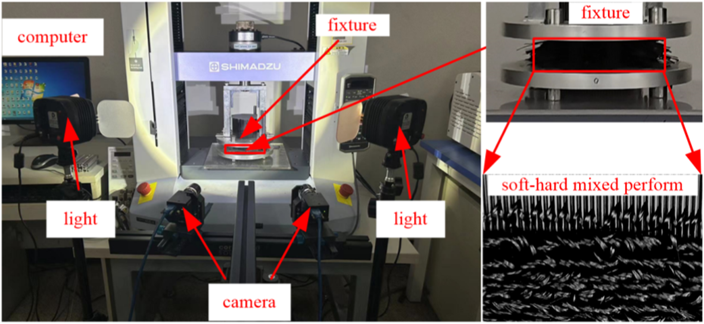
Soft-hard mixed preforms have been commonly compressed and compacted by unit. However, as the laying height increases, the fiber rebound height between layers varies, leading to non-uniformity in the fiber volume fraction between layers. To address this issue, a universal tensile testing machine was utilized to explore the compression and compaction rules of the preform. The mapping relationship between the number of multi-units, holding duration, compaction times, and the rebound height of fibers was analyzed to eliminate the fiber rebound characteristics and improve the uniformity of the fiber volume fraction between layers. In this paper, multi-units were defined as composed of five units, resulting in a total of 15 three-dimensional stacking fiber layers. The experimental materials, main equipment, and instruments used in this study, experimental method and experimental process are as follows: 1. Experimental materials: 3k fibers TORAY T300B; Theφ1.2 mm carbon rod is extruded by 3k fibers of TORAY T300B. 2. Main equipment and instruments: The universal tensile testing machine of SHIMADZU AGS-X, The camera of Hikvision MV-CH250-90GM. 3. Experimental method: Using “the constant velocity compression method” (compressing the sample at a certain speed to a constant displacement), the compression load is 12,000 N when the minimum height of the preform is reached. 4. Experimental process: The preform and tooling which is laid with special fixture but not compression compaction are placed on the SHIMADZU AGS-X universal tensile testing machine. First, the preform is compacted by constant speed of 1 mm/min using “the constant velocity compression method,” until the height of the compressed sample basically do not change. Second, it will release the load or maintain the compression load for a period of time according to the process. Finally, the load is released and the pressure head moves to the original position at a constant speed of 10 mm/min. Repeat the above steps (1–3) to apply cyclic loads to the preform. Paying attention to weaving the new preform for the next experiment to obtain different experimental results. Using the Hikvision MV-CH250-90GM camera to capture images of the preform after load release to measure the fiber rebound height. The experimental platform is shown in the Figure 2. The equipment and instruments.
Detailed experimental methods can be found as follows:
The method for measuring the rebound height of fibers
To measure the rebound height of fibers after load release, a machine vision approach is employed in this study. The captured original image pixels are denoted as α, as shown in Figure 3(a). Firstly, the original image is binarized, and morphological dilation is used to define the processed image pixels as β, as shown in Figure 3(b). Subsequently, β and α are combined using equation (1) to obtain new image pixels, capturing effective pixel points in the image, and the least square method is utilized to fit the fiber edges. At this point, the image pixels are represented by δ. Finally, a high-precision calibration board with an accuracy of ±0.005 mm is used for camera calibration, and δ is converted to the actual distance to obtain the actual rebound height of fibers, as shown in Figure 3(c).where t denotes the compaction height of multi-units, records by universal tensile testing machine, mm; T denotes the rebound height of fibers, mm. The method for measuring the rebound height of fibers. (a) Original. (b) Binary. (c) Calibration.
The mapping relationship between the number of multi-units and the rebound height of fibers
Process parameters.

The data fitting method was applied by Table 1 “the average rebound height of sample ” to segment the experimental data to obtain the mapping relationship between the number of multi-units and the rebound height of fibers, as presented in Figure 4. The mapping relationship between the number of multi-units and the rebound height of fibers.
As depicted in Figure 4, there exists a positive correlation between the rebound height of fibers and the number of multi-units after load release. The rebound height of fibers increases with an increase in the number of multi-units. When the number of multi-units is small, the rebound height of fibers exhibits a gentle increasing trend. However, as the number of multi-units increases, the trend of the rebound height of fibers becomes more apparent. The overall trend indicates that the rebound height of fibers varies linearly with the multi-units and can be represented by the linear equation y = ax + b.
The mapping relationship between the holding duration and the rebound height of fibers
Process parameters.
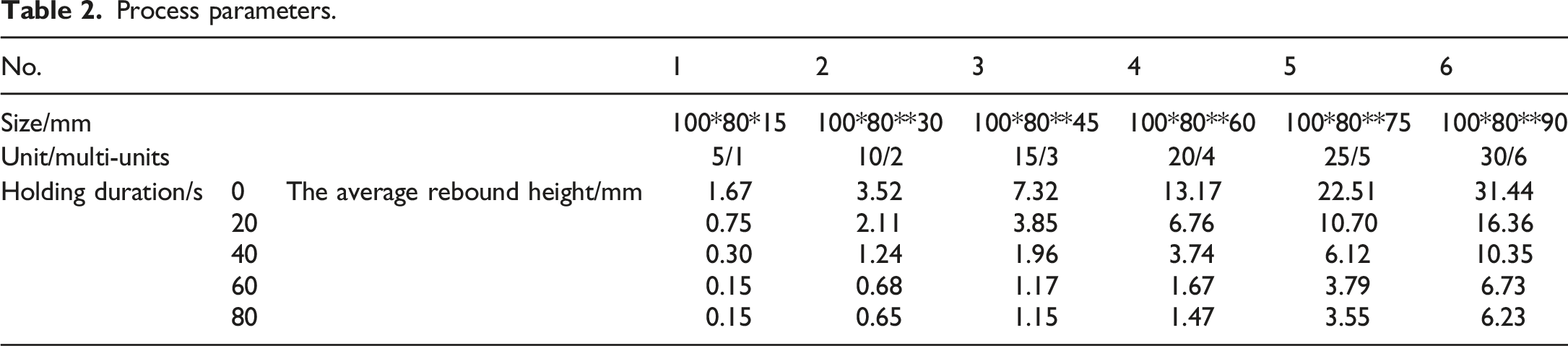
The data fitting method was applied by Table 2 “the average rebound height of sample” to obtain the mapping relationship between various holding durations and the rebound height of fibers, as depicted in Figure 5. The mapping relationship between the holding duration and the rebound height of fibers.
Based on the findings presented in Figure 5 it is observed that the rebound height of fibers after load release experiences a decline as a function of time, which corresponds to a phenomenon referred to as “elastic decay” of multi-units. The trend of the rebound height of fibers varies with different holding durations. Specifically, an evident downward trend is observed when the holding duration increases from 0 s to 20 s. Thereafter, the decline in the rebound height of fibers becomes less pronounced during the holding durations of 20 s to 40 s and 40 s to 60 s. It is noteworthy that, for holding durations greater than 60 s, the rebound height of fibers remains relatively constant.
The mapping relationship between the compaction times and the rebound height of fibers
Process parameters.

The ExpAssoc function model was used by Table 3 “the height of preform” to establish the mapping relationship between compaction times and the rebound height of fibers, as depicted in Figure 6. The mapping relationship between the compaction times and the rebound height of fibers. (a) 1-multi-units compaction. (b) 2-multi-units compaction. (c) 3-multi-units compaction. (d) 4-multi-units compaction. (e) 5-multi-units compaction. (f) 6-multi-units compaction. Where i0 denotes load apply; i1 denotes load release; i denotes compaction times.
The fitted relationship after data organization is:
According to Figure 6 and equation (2), it is evident that the rebound height of fibers decreases gradually after each multi-units compaction. When the number of compaction times is less than 3, the rebound height of fibers is greater, but the reduction rate is the highest. As the number of compaction times increases, the rebound height of fibers gradually decreases, and the rate of decline slows down. Upon exceeding five compaction times, the rebound height of fibers approaches 0, indicating that the overall size of the multi-units tends to stabilize. This implies that after multiple cycles of compaction, the thickness of inter-laminar fibers gradually stabilizes. The increase in compaction times results in a decrease in the elastic deformation energy of inter-laminar fibers, which exhibits nonlinear viscoelastic properties. The overall trend of change suggests that there exists a non-linear relationship between the rebound height of fibers and the compaction times, which can be accurately represented by
The design of multi-units variable duration cyclic compaction process
Response surface methodology and regression model
The design and results of response surface experiment.

A second-order polynomial approximation model was applied to perform multiple regression fitting on the experimental data presented in Table 4. This analysis aimed to establish a prediction model that correlates three factors with the rebound height of fibers:
Analysis of variance and validation of the degree of significant effect
Analysis of variance and validation of the degree of significant effect.
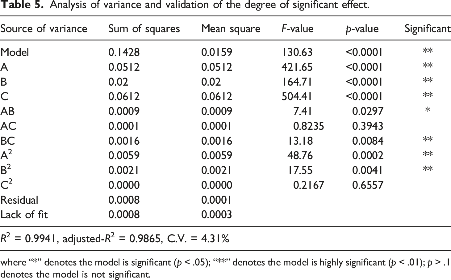
where “*” denotes the model is significant (p < .05); “**” denotes the model is highly significant (p < .01); p > .1 denotes the model is not significant.
From Table 5, it is evident that the regression model exhibits a remarkably low p-value of less than .0001, underscoring its high level of statistical significance. Furthermore, the individual p-values associated with the number of multi-units A, holding duration B, compaction times C, the interaction term BC between holding duration and compaction times, the quadratic term A2 representing the number of multi-units, and the quadratic term B2 representing holding duration, all display p-values below .0001. These results unequivocally demonstrate the profound impact of these six factors on the regression model. Moreover, the p-value associated with the interaction term AB between the number of multi-units and the holding duration is less than .05, further affirming its significant influence on the regression model. Conversely, the p-value associated with the interaction term AC between the number of multi-units and the compaction times, as well as the quadratic term C2 representing holding duration, exceeds 0.1, indicating that these two factors have an insignificant impact on the regression model. The F-value serves as a valuable metric for assessing the influence of different factors on the rebound height of fibers within the model. Based on this analysis, it can be inferred that the factors, ranked in order of significance from strongest to weakest, are C, A, B, A2, B2, BC, AB, AC, and C2. The determination coefficient (R2) and adjusted determination coefficient (Adjusted R2) both approach 1, indicating that the quadratic regression model exhibits a high degree of explanatory power. Furthermore, the coefficient of variation (C.V.) is 4.31%, further confirming the model’s reliability. To evaluate the performance of the regression model, the predicted rebound height of fibers derived from the model was compared to the actual values through a scatter plot, as illustrated in Figure 7 The actual scatter plot and the predicted value of rebound height of fibers.
Parameter optimization
In the regression model for the rebound height of fibers, the optimal parameters were determined by minimizing the rebound height of fibers. The derived optimal parameter values are as follows: three multi-units, a holding duration of 57 s, and two compaction times. These parameter values were subsequently substituted into equation (4), resulting in a predicted rebound height of fibers of 0.235 mm.
Experimental results and discussion
Experimental conditions and testing methods
To verify the impact of multi-units variable duration cyclic compaction on the preform, three sets of experimental samples were prepared using both the original process and optimized process parameters. The preform consisted of 30 multi-units, and a digital device was utilized to measure the height of each multi-unit completed during the weaving process. The volume fraction of each multi-unit and the preform was calculated using the weighing method.
19
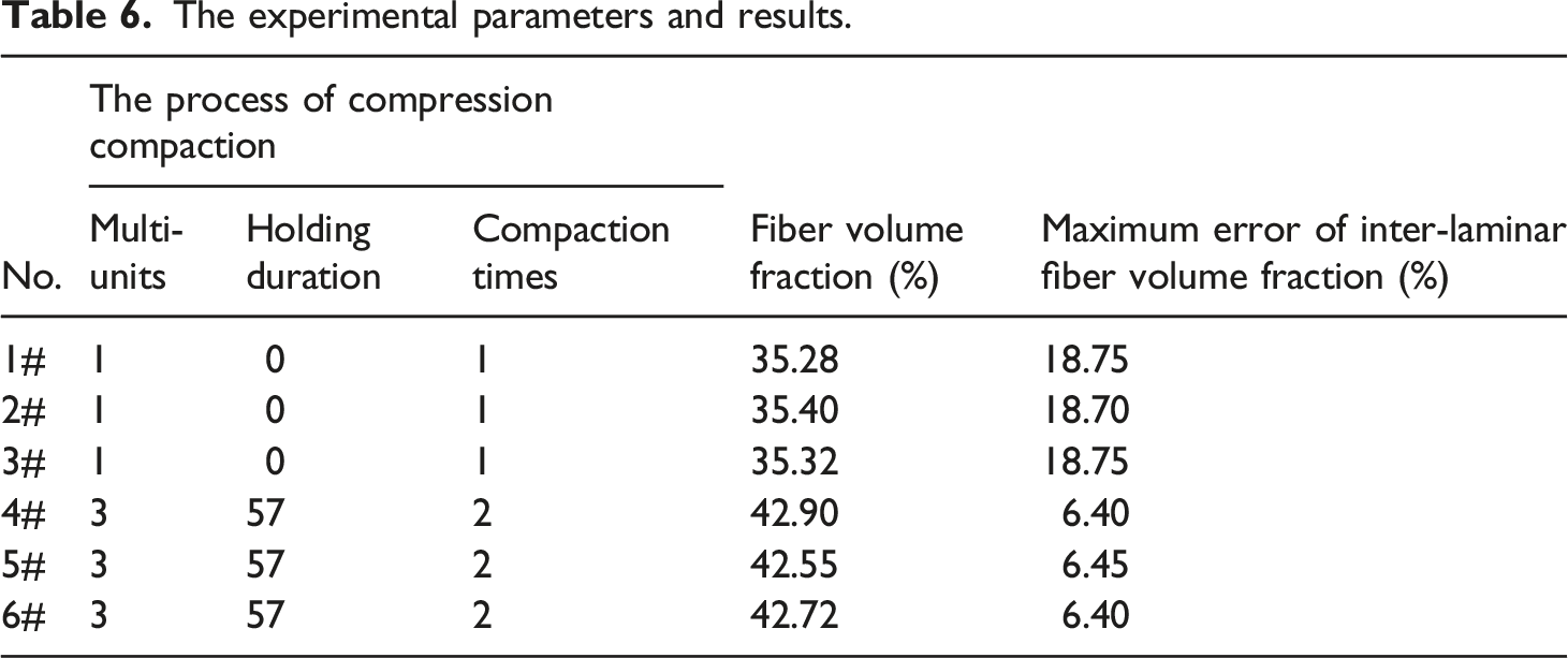
Additionally, the error between the inter-laminar fiber volume fraction was determined. These measurements were displayed on the human-machine interface (HMI), as shown in Figure 8(a). For precise examination of the preform’s morphology, an experimental sample was prepared using M9102 epoxy resin to cure a soft-hard mixed composite material. Slices were then obtained from the top, middle, and bottom sections of the composite material, as depicted in Figure 8(b). The experimental parameters and corresponding results are presented in Table 6. The experimental device and soft-hard mixed composite materials. (a) The digital device and HMI parameters. (b) The sample of soft-hard mixed composite material. The experimental parameters and results.
Results and discussion
Observing the compaction of fibers at different positions using Leica DVM6 optical microscope, as shown in Figure 9. The micro-morphology of soft-hard mixed composite material. (a) The micro-morphology of original process of compaction. (b) The micro-morphology of optimized process of compaction.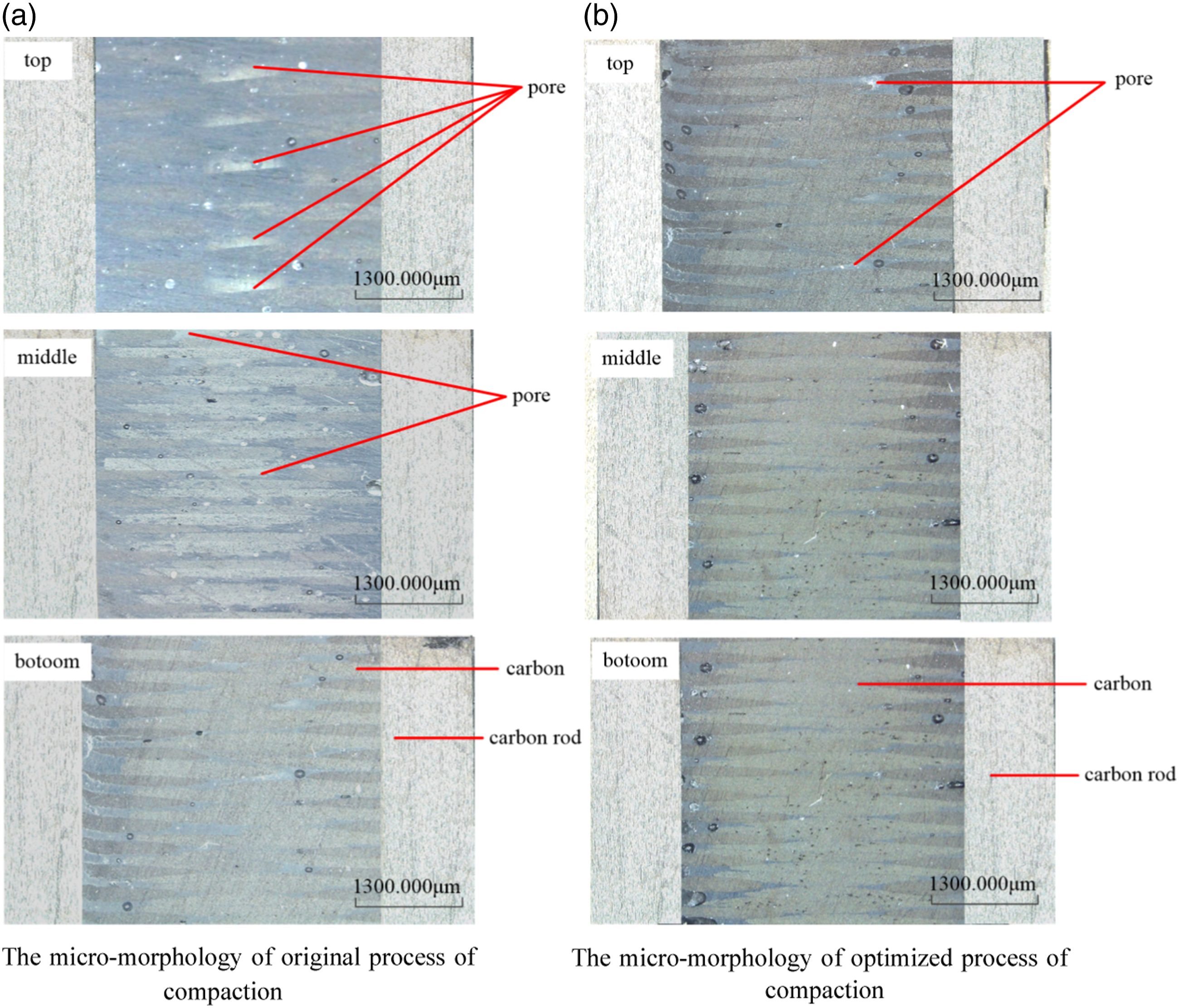
Figure 9(a) reveals the almost non-uniform compaction of the preform layers using the original process. The bottom part appears denser, likely attributed to multiple cycles of compression, resulting in a willow leaf-shaped cross-section of fibers. In the middle layer, a slight rebound is observed due to a lower number of compaction cycles compared to the bottom part. The cross-section of fibers in this region exhibits a rectangular shape with minor pores. On the top part, where minimal compaction times were applied, a more significant fiber rebound is evident. The fibers are loosely arranged, and larger pores are present, surpassing those observed in the middle layer. Figure 9(b) demonstrates the effects of the optimized process, employing multi-units variable duration cyclic compaction, on the compacted preform. Notably, the fiber rebound characteristics have been effectively eliminated. Across the top, middle, and bottom parts of the fibers, no rebound is observed. The cross-section of fibers exhibits a willow-shaped configuration, attributed to the compaction process. Additionally, the top part displays fewer pores compared to the other regions, indicating an enhanced inter-laminar fiber density.
Conclusions
This paper addresses the issue of non-uniform fiber volume fraction between layers during the compression and compaction process of soft-hard mixed preforms. To tackle this problem, a approach called the multi-units variable duration cyclic compaction method is proposed. This method takes into account the compression viscoelastic deformation behavior of inter-laminar fibers and aims to systematically eliminate the rebound characteristics exhibited by these fibers. By doing so, it effectively reduces the error associated with the inter-laminar fiber volume fraction. Moreover, the proposed method offers valuable theoretical guidance for achieving enhanced stability and precise control of the z-direction in soft-hard mixed preforms. In summary, the key contributions and findings of this paper can be summarized as follows: (1) Through the process of fitting the experimental data, a comprehensive mapping relationship was established between the number of multi-units, holding duration, compaction times, and the rebound height of fibers. The findings revealed that the number of multi-units and the rebound height of fibers exhibited a linear relationship, with a increase in the rebound height observed as the number of multi-units increased. Additionally, a negative correlation was identified between the holding duration and the rebound height of fibers, indicating that an increase in the holding duration resulted in a decrease in the rebound height of fibers. Furthermore, an exponential relationship was observed between the compaction times and the rebound height of fibers, indicating that as the compaction times increased, the rebound height of inter-laminar fibers decreased and eventually reached a stable state. (2) The Box-Behnken response surface design method was employed to establish the experimental plan for compression compaction, aiming to optimize the preform compaction process and investigate the control mechanism of inter-laminar fiber volume fraction. The computational analysis revealed that the combination of three multi-units, a holding duration of 57 s, and two compaction times yielded a desirable rebound height of fibers measuring 0.235 mm. These findings underscore the high reliability of the regression model within the chosen range of experimental parameters, affirming its potential for accurately predicting experimental outcomes. (3) The process parameters are optimized from unit compression compaction process which is “laying one unit and compacting one time without holding duration” to a multi-units variable duration cyclic compression compaction process which is “3 multi-units and compacting two times with holding duration of 57 s in each stage.” The micro-morphology of the preform was examined using an optical microscope to assess the density of inter-laminar fibers before and after process optimization. Simultaneously, a digital device was utilized to measure the fiber volume fraction of the preform after implementing the optimized process, resulting in a value of 42.90%. This represents a significant improvement of 12.16% compared to the pre-optimization state, with a maximum inter-laminar error of 6.45%, which is 190.70% higher than before the optimization of process. These findings serve to validate the reliability of the multi-units variable duration cyclic compaction process.
However, there are many factors affecting the compression compaction of the preform. Some factors, such as the change of compression load, changes of compression displacement, the number of laying fibers, the content of additive and ultrasonic vibration assistance, all affect the quality of preform. It will point for the next research and work.
Footnotes
Acknowledgements
The authors gratefully acknowledge the support from Tianjin Science and Technology Committee towards this study.
Declaration of conflicting interests
The author(s) declared no potential conflicts of interest with respect to the research, authorship, and/or publication of this article.
Funding
The author(s) disclosed receipt of the following financial support for the research, authorship, and/or publication of this article: This work is supported by The key technologies R&D program of Tianjin (Grant nos. 15ZCZDGX00840) and The natural science foundation of Tianjin (Grant nos. 18JCYBJC20200).