
Abstract
The auxetic property of macro-porous rotating square structure has been investigated by many using either experimental or numerical approaches. Given the low breaking strength of the typical rotating square structure, it was proposed to employ an elastic base material to the cellular auxetic structure to improve its strength while maintaining its auxetic behavior in our previous study. Despite the experimental studies conducted, a numerical analysis is needed to explain the auxetic effect found in the produced laminated fabrics. In this paper, the auxetic properties of the 2-layer laminated system were simulated using the finite element approach and the effects of the modulus difference between the frame and the base were discussed. The main findings are (1) the simulated results based on a simplified model are broadly consistent with experimental ones under low tensile strain ranges; (2) the initial modulus of the frame material in the stretched direction and that of the base material in the lateral direction are critical to the generation of auxetic effect in the laminated system; (3) at least a 10-time difference of the modulus between the frame and the base materials is required to generate an auxetic effect in the 2-layer laminated structure and the overall auxetic property is increased by enlarging difference of the modulus within a tolerance. It is expected that this research could provide an instructive reference for the future design of auxetic materials.
Introduction
Auxetic materials are known for their exceptional deformation behavior under external forces, demonstrating a transverse enlargement or contraction when stretched or compressed longitudinally. Since the report of auxetic foams in 1987, 1 auxetic materials have experienced tremendous development, covering a series of materials such as fibers,2–4 yarns,5–7 knitted fabrics,8–10 woven fabrics,11–13 composites,14–17 and metamaterials,18–21 etc. Due to the unique deformation behavior and energy absorption ability, auxetic materials have demonstrated great potential applications in perfect-fitting clothing, protective equipment, high-performance footwear, high-sensitivity transducers, soft robots, wearable devices, and even aircraft components, etc.22–26
The exploitation of auxetic materials largely depends on the understanding of their internal structures. According to the monographs,27–29 re-entrant cells, rotating polygons, chiral/anti-chiral lattices, nodule-fibril models, missing-rib models, and those with elastic instability are among the most typical geometrical structures that can achieve auxetic behavior. The mechanism of rotating polygons was first reported by Grima et al. with the use of rotating rigid squares as an example. 30 The rotating of rigid square units around the selectively connected hinges accounts for its overall auxetic effect. In their mathematical model, the Poisson’s ratio of this structure was a constant of −1 if the square units were perfectly rigid and did not deform upon loading. This system still stands even if the square unit is replaced by other designs, such as a rigid cross/triangle/parallelogram, hierarchical ensemble, or a frame with non-space filling31–33 During the exploitation process of the rotating square structure, it should be noticed that it is almost impossible to produce a material with ideal rigidity. To reveal the importance of the rigidity of the square unit, Grima et al. developed a model with semi-rigid squares by adding an additional degree of freedom. 34 Its Poisson’s ratio, instead of being constant, was influenced by the deformation of squares, the loading direction, as well as the initial angles between squares. Later, the model was improved by assuming the square units to be only deformable in the edge length. It further confirmed that the auxetic effect of this system mainly depends on the angle between squares and the loading direction, but is independent of the size of the squares. 35 Since it is of possibility that the polygon unit in this system can be of various shapes, a rotating model with different-sized rigid squares/rectangles was created for mechanical property and auxetic property analysis. 36 It turned out that its auxetic effect was scale-independent in particular stretching directions while dependent on the shape, the relative size of rectangles, and the angle between them. Beyond that, a massive quantity of analytical research has been done on the rotating structures with units evolved from the rotating quadrilaterals, such as rotating rhombi, rotating parallelograms, and rotating triangles. 32 The extensive variations based on rotating rigid units revealed vast possibilities, but it is worth noting that the deformation behavior of real-life materials with the rotating rigid units may differ from that in simulations and that their auxetic property can be affected by various parameters.
From a perspective of easy application, auxetic systems resembling the rotating rigid units were proposed by introducing patterned slit perforations into a sheet material. 37 Taylor et al. conducted a numerical simulation on a periodic geometry, in which a 2D metallic sheet is perforated with a square array of mutually orthogonal elliptical voids. 38 The results showed that the auxetic behavior could be achieved when the aspect ratio was increased to a certain value, at which point the deformation behavior of the structure showed similarity to that of the rotating square geometry. Slit perforated systems with each slit oriented in a quasi-random and disordered manner were simulated in terms of deformation behavior and Poisson’s ratio under stretching. 39 Samples were produced from rubber sheets for experimental work. Deviations were found between the simulated and experimented results, which could be attributed to the edge effect and out-of-plane deformations in the latter case. The rotating square structure was also realized by laser-cutting an ordered pattern of slits on non-woven fabrics. 40 The non-woven fabrics exhibited an auxetic effect during tensile loading but a significant reduction in breaking force, and the out-of-plane deformation of unit cells was found to be related to the homogeneousness of the fabric. This method of cutting the rotating rigid unit structure out of fabric is quite applicable in real life to manufacture auxetic materials, but the reduction in its breaking strength could be a major limit to its application prospects. One solution to keep the auxetic effect of fabrics with rotating units without sacrificing the fracture strength was proposed in our previous work by attaching the perforated frame of rotating units to a complete base material. 41 Fabrics were fabricated by first laser-cutting a highly stable woven fabric into different frame structures, and then laminating the cut frame(s) with a higher-elastic base fabric using hot-melt adhesives. Auxetic effects to various extents were shown in those laminated fabrics when subjected to uniaxial tensile loading, but the experimental results could not provide a systematic understanding of the deformation behavior of the composite system and the effects of the base material on the overall auxetic effect.
In view of the above, a numerical analysis is conducted on the composite system with the rotating square structure in this work. First, a simplified model simulating the rotating square frame under the constraint of the base is established based on the experimental parameters. Second, the auxetic effect and the deformation behavior of the composite system under increasing uniaxial tensile strains are simulated, in comparison with the previous experimental results. The contribution, as well as the defects of the simplified modeling, are discussed. Finally, the effects of the modulus difference between the frame and the base on the overall auxetic property are analyzed. Overall, the findings from this study can work as a theoretical grounding and guide the future design of auxetic composite fabrics.
Experimental backgrounds
To ensure the integrity of this research, the previous experimental work
41
must be first introduced in brief. Based on the rotating square geometry, auxetic fabrics were developed using the lamination technique. The manufacturing process of a typic 2-layer laminated fabric is shown in Figure 1. The frame fabric was first attached to the hot-melt adhesive membrane with backing paper under 150°C for 30 s and then was laser-cut into the designed rotating square structure using Han’s Yueming Laser CMA1309-B-A machine. After that, the backing paper of the adhesive membrane was removed and the adhesive side of the frame fabric was finally attached to the base fabric again by heating it to 150°C for 30 s. The material specifications and properties of a typical 2-layer laminated fabric (sample No. L2-PW-RS2 in
41
) are listed in Table 1. Since the high content of spandex in the base fabric makes its thickness and properties easily change under heat setting, the parameters of the base fabric before and after heat setting were thus measured. Uniaxial tensile tests were conducted on each fabric material using Instron 4411 Universal Testing Machine. The true stress-strain curves were generated, and data in the first 10% of strains were subjected to linear fitting, with the slope representing the initial modulus (MPa) of each fabric material. The rotating square geometry in the 2-layer laminated fabric is sketched in Figure 2(a) and (b), with the dimensional parameters listed in Table 2. The photo of a typical real fabric sample is shown in Figure 2(c). All of the laminated fabric samples underwent uniaxial tensile loading tests on an Instron machine with the lateral dimensional changes which were monitored with a digital camera. Poisson’s ratios of each laminated fabric sample under increasing tensile strains were calculated to characterize its auxetic property. More details regarding the experimental tests are provided in the reference.
41
Manufacture process of 2-layer laminated fabrics. Material specifications and properties of a typical laminated sample (No. L2-PW-RS2). The rotating square geometry in the 2-layer laminated fabric. (a) a repeating unit; (b) frame design for laser cutting; (c) photo of a real fabric. Dimensional parameters of the rotating square frame.


Modelling
Model establishment
The base and frame fabrics used in the experiments possess different structures, with the former tricot knitted and the latter twill woven. It is quite complicated to establish mesoscale models showing the intermeshing or interlacing of yarns. Though models at the yarn level may bring about results closer to experimental ones, it is undeniable that it makes the computation much more time-consuming and is problematic for generalizing the simulation results to other materials, or other fabrics with different structures. Therefore, a simplified model was established by seeing each fabric component as a 3-dimensional continuous part. Extracting dimensions from the fabric samples, as listed in Table 1 and Table 2, geometric models of the frame and base parts were created respectively in Abaqus, as shown in Figure 3(a). The width of both parts (in the x direction) equals w
t
, and the length (in the y direction) equals h
t
. The thickness of the frame part (in the z direction) equals that of the frame fabric and the thickness of the base part equals that of the heat-set base fabric. The adhesive membrane layer was neglected in the model, and instead, the two parts were combined together using a tie constraint. For one thing, the thickness of the adhesive did not affect the final thickness of the 2-layer laminated fabric, which can be told from the measurements in Table 1. For another, the possible relative slippage between the frame and base parts was considered a defect in the realization of auxetic laminated fabrics. The avoidance of relative slippage via tie constraint could provide a more ideal condition under which the auxetic effect of the laminated system under unidirectional tensile strains is presented. The appearance of the model of the composite system in the x-y plane is shown in Figure 3(b). The geometric structure of the model is identical to the sample area between two clamps in the real tensile tests. The boundary conditions were determined, as shown in Figure 3(b). The bottom edge of the model is constrained from translation and rotation in any direction, while the upper edge is subjected to a y-directional displacement of 15 mm, which equals 10% of its initial length. This simulates the experimental process of keeping one end fixed while applying a longitudinal tensile strain to the laminated fabric sample on the other end. To shorten the computation time while maintaining accuracy, the frame part was seeded with a global size of 1.0 mm. Hex-dominated elements, C3D20 R, C3D15, and C3D10H, were employed for the meshing of the frame part. The base part was seeded with a size of 0.8 mm and meshed with C3D20 R elements only. Geometric models of the 2-layer laminated fabric with a rotating square structure. (a) two component parts; (b) a 2-layer laminated model.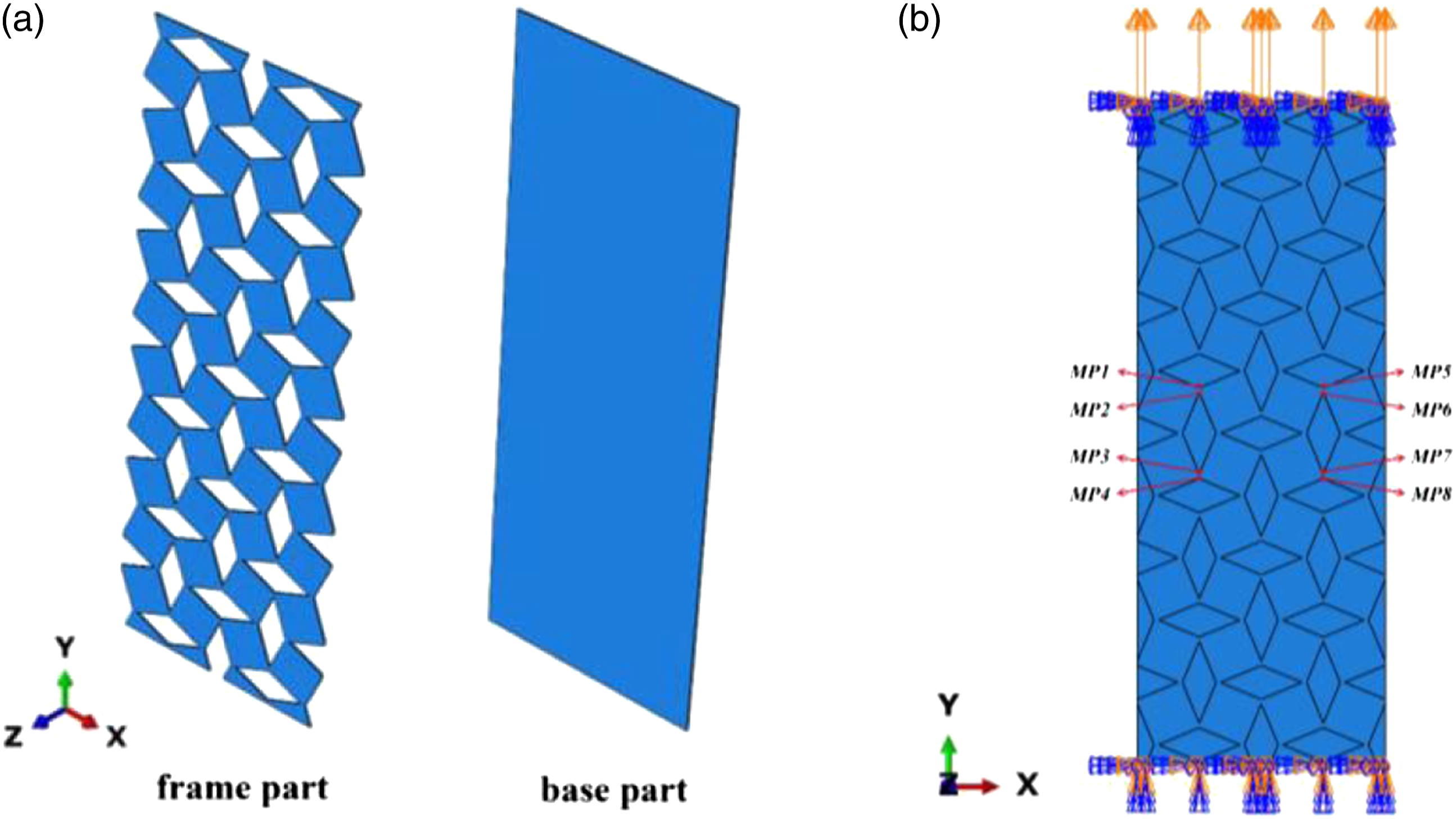
Material properties
The fabrics used for the production of laminated fabrics were anisotropic without a doubt, but the material properties of the models were considered isotropic in the simulation for two reasons. First, it is of particular difficulty to determine the anisotropic elastic properties of thin fabrics with high precision. Second, similar to the reason why the microstructural features of the fabrics were neglected, it is of little meaning to fully emulate the fabric properties in the model. In the case that the homogeneous isotropic properties are adopted, more generalized conclusions could be generated regarding the effects of the base part on the deformation behavior of the rotating square frame and the effects of the modulus difference between the two parts on the overall auxetic effect. The elastic properties of the materials were determined based on experimental measurements. It is known from our previous studies that the auxetic effect of the laminated fabrics mainly arises from the rotating of the square units in the frame part to the loading direction (warp direction for instance). 41 The rotating of squares relies on the rigidity of the frame area, especially along the warp direction, and the extensibility of the base area, especially in the weft direction. Under this circumstance, it was assumed that the elastic modulus of the frame area in its stretching direction (warp direction) and the elastic modulus of the base area in its lateral direction (weft direction), are of critical importance to the generation of auxetic effect in the laminated system. Considering that the frame area was formed with the laminated fabric while the base area only contained the heat-set base fabric, the initial modulus of the laminated fabric in the warp direction and the initial modulus of the heat-set base fabric in the weft direction were used as the elastic modulus of the frame part and the base part respectively to simulate the auxetic effect of the composite system under warp-directional tensile loadings. Likewise, the initial modulus of the laminated fabric in the weft direction and the initial modulus of the heat-set base fabric in the warp direction were used as the elastic modulus of the frame part and the base part respectively to simulate the auxetic effect of the composite system under weft-directional tensile loadings. The initial modulus values of the materials under warp and weft directions were listed in Table 1. Furthermore, the Poisson’s ratio values of the base and frame materials were measured using uniaxial tensile tests, determined as 0.15 and 0.35 respectively.
Data output and processing
The Poisson’s ratio measurement method of the model is in accordance with that used for fabric samples in experiments. The x-directional displacements of the eight measurement positions (MP1∼MP8), as marked out in Figure 3(b), as well as the y-directional displacements at the upper constrained line, were outputted. With the collected data, the change in the lateral width of the model can be determined using transverse displacements (u1) from

With the true strain in the tensile direction given by
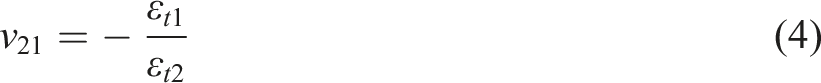
Substituting equations (2) and (3) into (4) enables the acquirement of the Poisson’s ratio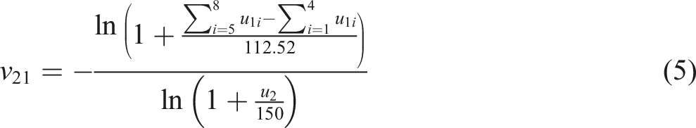
Results and discussions
Poisson’s ratio results
The simulated Poisson’s ratio results of the model under warp- and weft-directional tensile strains are shown in Figure 4, in comparison with the experimental results. Under warp-directional tensile strains, the auxetic effect of the model peaks at the very initial stage of the tensile process with a negative Poisson’s ratio of −0.79. Within the tensile range of 0–3%, the variation of simulated results is almost the same as the experimental ones. However, as the tensile strain grows from 3% to 9.5%, the two curves start to split apart, and the gap in between is increasingly enlarged. The simulated results of Poisson’s ratio increase from negative to positive at the tensile strain of 4% at a gradually decreasing rate. By contrast, the increase of the experimental results drops rapidly at the tensile strain of 4%, and the threshold value for the tensile strain when the Poisson’s ratio turns from negative to positive is 6.7%. In general, the simulation results can only show a good agreement with the experimental results at the initial stage of tensile strains in the warp direction, and with the increase of tensile strains, the deviation from the experimental results is increasingly large. Under weft-directional tensile strains, the simulated Poisson’s ratio is around zero at the very beginning of the tensile process and gradually increases to 0.4 as the tensile strain increases to 9.5%. An almost non-auxetic behavior is shown in the model, the same as that in real fabrics. Both Poisson’s ratio results and variation trend in the simulation are close to those obtained from experiments, showing an overall good agreement. Comparing the growth rate of Poisson’s ratio results under warp- and weft-directional tensile strains, it is noted that in the simulation results, the growth rate is generally slower when stretched in the weft direction than in the warp direction, while a similar observation is only found from experimental results at the initial stage of tensile strains. Simulated Poisson’s ratio results in comparison with experimental results. (a) under warp-directional tensile strains; (b) under weft-directional tensile strains.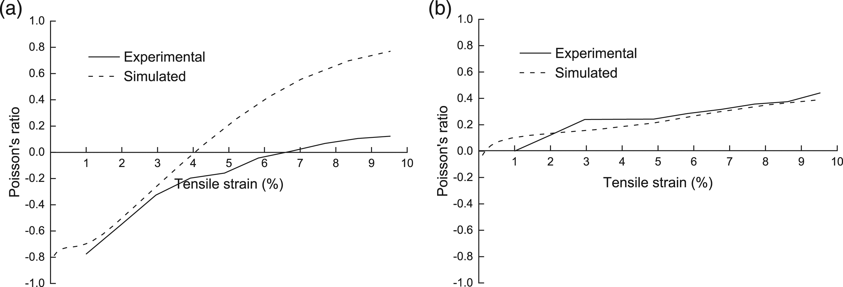
Deformation and stress distribution
Under warp-directional tensile strains
The in-plane deformation and stress distribution of the laminated model under different warp-directional tensile strains are shown in Figure 5, and the vertical views are shown in Figure 6(a). At the very beginning of the tensile process (1% tensile strain), the in-plane rotation of the square units in the model is significant. But the out-of-plane deformation is negligible, except for the curling at the two sides of the model (referred to as the edge effect hereinafter). With the increase of the tensile strain (from 1% to 7%), the out-of-plane deformation becomes increasingly notable in the form of not only edge effect, but also in-the-middle bumping-outs. The bulges in the middle area of the model are against the direction of the edge effect. Meanwhile, the square units show exacerbating distortions in the x-y plane. As the tensile strain continues to increase, the rotating of squares is mitigated while the distortion is aggravated, at which stage the measured Poisson’s ratio turns from negative to positive. By the end of the tensile process (9.5% tensile strain), the edge effect reaches its utmost and stops increasing, while the in-the-middle bulging keeps growing to a larger extent. Seeing from the 3-dimensional view of the model at the end of the tensile process in Figure 6(b), it is obvious that except for the areas around the bottom and upper edges which are constrained, the middle part of the model is wave-shaped, resembling that was observed from real 2-layer laminated fabric samples, as shown in Figure 6(c). Deformation and Von Mises stress distribution of the model under different tensile strains in the warp direction. Out-of-plane deformations. (a) vertical views of the model at different tensile strains; (b) 3-dimensional view of the model at 9.5% tensile strain; (c) the out-of-plane deformation shown in a real fabric sample; (d) different node types in the model.
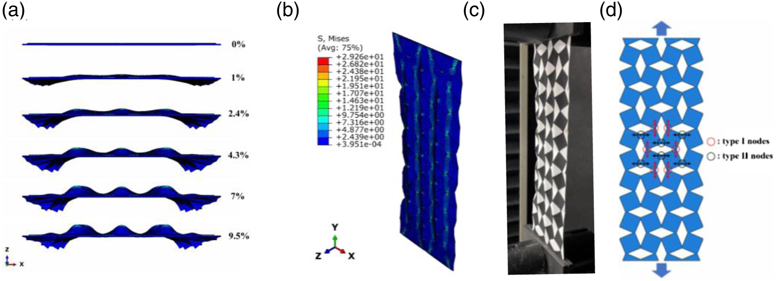
To better explain the stress concentration of the model when stretched, the nodes that connect the square units in the frame part are divided into two types. Type Ⅰ nodes are those that connect the squares arranged along the tensile direction, while Type II nodes are those that connect the squares in the direction perpendicular to the tensile direction. Some of them are marked out in red and black circles respectively in Figure 6(d) for demonstration. From Figure 5, it can be seen that the stress is concentrated around the node regions in the frame structure during the whole deformation process, especially around the type Ⅰ nodes. With the increase of tensile strains, the concentrated stress tends to spread from the type Ⅰ nodes to the central area of square units, and the diagonal regions of the squares in alignment with the tensile direction are under higher stress than other areas of the frame part. Combining the stress distribution with the out-of-plane deformation of the model, it can be known that the lower-stress areas tend to bulge out, leading to out-of-plane deformations, which may be a major factor that incurs a fast-decaying in-plane auxetic effect of the 2-layer laminated model under warp-directional tensile strains.
Under weft-directional tensile strains
The in-plane deformations and stress distribution of the model under different weft-directional tensile strains are shown in Figure 7. It can be seen that the highest stress is concentrated in the frame part around the type Ⅰ nodes. The stress concentration area is spread from the type Ⅰ nodes to the central area of the square units in the frame along the tensile direction, which is similar to the situation under the warp-directional tensile strains. What’s more, relatively higher stress is spread from type Ⅰ nodes towards the central rhombus-shaped base area. It infers that higher restricting force is applied by the base area to the rotating tendency of the squares in the frame when the model in stretched in the weft direction than in the warp direction. Deformation and Von Mises stress distribution of the model under different tensile strains in the weft direction.
From Figures 7 and 8, it can be observed that the model demonstrates both the rotating of squares in the x-y plane and the out-of-deformations in the x-z plane. Compared with the model when stretched in the warp direction, the rotating degree is smaller at the end of the tensile process due to the larger inhibition of the base material, and the out-of-plane deformations appear less significant in this case. By the end of the tensile strain of 4.9%, the edge effect is a major factor that causes the out-of-plane deformation, while bumping out in the middle part of the model is trivial. At the end of the tensile process (9.5% tensile strains), there appear to be three buckling positions in the middle of the model, two of them bumping out toward the z direction and the other toward the minus-z direction, which is different from the situation observed from Figure 6(a), where the three humps are all towards the z direction. The distinctively different deformation behavior, when stretched in the weft direction, indicates that the square units cannot rotate to their fullest extent under weft-directional tensile strains due to the higher constraint from the base material. It directly leads to the in-plane distortion of the squares, which further takes major responsibility for the non-auxetic effect shown in the fabric plane. Vertical views of the model showing out-of-plane deformations.
Discussion on the validity of the simplified model
The auxetic effects of the 2-layer laminated fabric structure were simulated herein using a simplified model. It is obvious that this model is a bit rough: (1) the microstructures of the fabrics and the anisotropic material properties were neglected; (2) the adhesive interface between the layers was idealized as perfect bonding without relative slippage. All of these simplifications may inevitably lead to deviation from the current experimental results. Via comparing the simulated results to the experimental ones, it was found that this model could provide relatively consistent results under low tensile strain ranges despite its simplification. Furthermore, it confirmed the significant role of the overall elastic property of the two parts, in particular, the initial modulus of the frame material in the stretched direction and the initial modulus of the base material in the lateral direction. Putting deviations aside, this model is more suitable to provide an instructive reference for the future design of auxetic laminated materials having similar rotating square geometry but different materials. For example, when the base-constrained rotating square structure is to be produced using additive manufacturing, or when other different materials, such as rubber, are to be used for the laminated layers, results from this model may be of value. In the next section, how the modulus difference between the base and frame parts affects the auxetic property of the composite system will be further investigated using the simplified model.
Effect of modulus difference on the auxetic property
Different modulus differences between the base material and the frame material.

Poisson’s ratio results
The simulated Poisson’s ratio results of the model with different elastic modulus ratios are shown in Figure 9. It is quite clear that all of the curves show a monotonically increasing trend but with different rates of rise. The larger the elastic modulus difference, the faster the increasing speed of the Poisson’s ratio. The minimum Poisson’s ratio values obtained in all cases are plotted as shown in Figure 10(a). Negative Poisson’s ratios are achieved at the initial stage of tension when the elastic modulus ratio changes from 1:10 to 1:100. But for the model with modulus ratio of 1:1 or 1:5, the minimum Poisson’s ratio value is positive, indicating that the auxetic behavior is unattainable if the modulus difference is smaller than a threshold value. It is also noted that at the modulus ratio of 1:10, the minimum Poisson’s ratio is around −0.07, and as the modulus difference widens, the minimum value of Poisson’s ratio decreases. When the modulus ratio equals 1:100, the minimum Poisson’s ratio approaches −0.66, meaning that the maximal auxetic behavior increases with the increase of the modulus difference between the two parts. Poisson’s ratio results of the model with different elastic modulus ratios. Comparison between the results obtained from different modulus ratios. (a) minimum Poisson’s ratio; (b) tensile strain range of auxeticity.

In addition, the decrease rate of the minimum Poisson’s ratio varies with the increase of modulus difference. As the elastic modulus ratio changes from 1:1 to 1:100, the decrease in the minimum value of Poisson’s ratio is fast at first, and then gradually slows down. It implies that the effect of the enlargement of modulus difference on the auxetic effect of the 2-layer laminated model is more drastic when the modulus difference is small, and, on the other hand, when the elastic modulus gap between the two materials becomes increasingly widened, the boosting effect of the enlarging modulus difference on the auxetic property of the model becomes smaller. The tensile range showing negative Poisson’s ratio also differs with the change of elastic modulus ratio from 1:10 to 1:100. A histogram is plotted in Figure 10(b) to display the tensile strain ranges showing auxeticity at different modulus ratios. When the modulus ratio equals 1:10, the tensile strain range showing auxetic behavior is quite narrow, almost 0.2%. When the elastic modulus difference is widened to the ratio of 1:20, the tensile strain range of auxeticity spikes to 1.5%, 7.5 times that in the case of 1:10. As the modulus difference is further enlarged to the ratio of 1:50, the tensile range showing negative Poisson’s ratio gradually increases to 3%. When the elastic modulus ratio is in the scope of 1:50 to 1:100, the tensile strain range of auxeticity fluctuates in the range of 2.8%–3.3%. At this stage, the enlargement of the elastic modulus difference has little effect on the tensile strain range of auxetic effect.
Deformation behavior and stress distribution
The deformed states of the model with different elastic modulus ratios at the end of the tensile process (10% tensile strain) are shown in Figure 11. It can be seen that the edge effect is increasingly obvious as the elastic modulus difference gets larger. When the modulus ratio is in the range of 1:1 to 1:10, the edges at two sides of the deformed model are very smooth. And as the ratio changes from 1:20 to 1:60, the indentations at the two edges become deeper and sharper. When the modulus ratio ranges from 1:70 to 1:100, the variations in the edge effect are too minor to identify. It infers a relatively small out-of-plane deformation when the modulus ratio is within 10 times, an increasingly large out-of-plane deformation during the range of 1:20 to 1:60, and an almost unchanged out-of-plane deformation as the modulus difference reaches 70 times and above. In-plane deformation of the model with different elastic modulus ratios at the end of the tensile process. (a) 1:1; (b) 1:5; (c) 1:10; (d) 1:20; (e) 1:30; (f) 1:40; (g) 1:50; (h) 1:60; (i) 1:70; (j) 1:80; (k) 1:90; (l) 1:100.
To visualize the out-of-plane deformation, the deformed states of the model in the x-z plane are shown in Figure 12. It is obvious that there exists almost no out-of-plane deformation when the elastic modulus of the frame material equals that of the base. When the modulus of the frame increases to five times that of the base, the out-of-plane deformation barely shows in the middle part of the model, but the edge effect starts to appear. As the elastic modulus gap between the base and the frame is widened to the ratio of 1:10, the middle part of the model would bend into the z direction and minus-z direction alternatively along the tensile direction, forming a cross profile of a sine curve. When the modulus of the frame reaches 20 times the base, the edge effect gets more severe, and all of the bends in the middle part of the model are towards the z direction, forming three bumps in the cross profile. With the increase of the modulus difference between the base and the frame to a ratio of around 1:60, the out-of-plane deformation shown in the model is increasingly aggravated. But as the elastic modulus difference between the two parts keeps broadening, the out-of-plane deformation featuring the bumping-outs in the x-z plane is kept almost unchanged. This shows that at a lower level of the elastic modulus difference between the frame material and the base material, the out-of-plane deformation gets more severe with the widening of the modulus difference. But there exists a limit to the out-of-plane deformation of the model, beyond which the increasing of modulus difference barely has effects. Out-of-plane deformations of the model with different elastic modulus ratios at the end of the tensile process. (a) 1:1; (b) 1:5; (c) 1:10; (d) 1:20; (e) 1:30; (f) 1:40; (g) 1:50; (h) 1:60; (i) 1:70; (j) 1:80; (k) 1:90; (l) 1:100.
The stress distribution of the model with different modulus ratios can also be observed in Figure 11. As shown in Figure 11(a), the stress is almost evenly distributed across the whole model when the elastic modulus of the frame material is the same as that of the base material. As the elastic modulus of the frame material increases to 5 times that of the base material, the stress is more concentrated on the frame part, and partly on the base part where the rhombi are aligned perpendicular to the tensile direction. From Figure 11(c) and (d), it can be seen that when the modulus ratio between the base material and the frame material turns from 1:10 to 1:20, the stress is more concentrated on the frame part, especially on the square diagonals which tend to be aligned with the tensile direction. At the time when the modulus of the frame material rises to over 30 times that of the base material, as shown in Figure 11(e) and (l), the stress becomes more and more concentrated around the type Ⅰ nodes. And the maximum value of the concentrated stress in the model keeps growing with the increase in the gap between the modulus of the base material and the frame material. It reveals a close relationship between stress concentration and out-of-deformation. It seems that the larger modulus difference between the two parts would lead to a more severe stress concentration in the model, and thus a more distinct out-of-plane deformation, but this influential relationship gets diminished when the modulus ratio exceeds 60 times.
Discussion
Since the auxetic rotating square structure has experienced plenty of research analytically, numerically, or experimentally, comparisons between the current study and the previous outcomes will be made in this section. The auxetic behavior of the 2-dimensional rotating square structure was first found by Grima et al. to be stable with a constant Poisson’s ratio of −1, under the assumption that the squares do not deform upon loading. 30 Apparently, this idealized scenario cannot provide a good prediction of auxetic behavior in real materials with such a structure. In view of imperfect rigidity in real materials, the auxetic behavior of the model with connected semi-rigid squares was studied analytically. 34 This improved model provided a better description of the auxetic behavior of zeolite frameworks than the original rigid one, although it overestimated the extent of auxeticity. Also, this analytical model is not suitable for the prediction of the auxetic behavior of the fabrics designed based on the rotating square structure. In 2019, Dubrovski et al. put the rotating square structure into reality by employing a highly ordered pattern of slits in non-woven fabric. 40 Their experimental research found out-of-plane deformations in the samples dependent on the homogeneousness of the nonwoven fabric. The more equally distributed and oriented fibers lie in both directions of the non-woven fabric, the smaller the out-of-plane rotation. Furthermore, a significant reduction in the breaking force of the fabric was caused by the induction of auxetic geometry, which means that the laser-cut auxetic geometry is only applicable under low tensile loads. Comparatively, a composite structure combining a rotating square frame and a base is studied in this paper using the finite element approach. Its in-plane auxetic effect as well as out-of-plane deformation is found to be dependent on the modulus differences between the frame and the base. The out-of-plane deformation has also been found in other membrane materials exhibiting an auxetic rotating mechanism. Mizzi et al. introduced microstructural cuts in a rubber sheet by laser cutting and analyzed the deformation profiles experimentally and numerically. 19 In their samples, the joint/ligament out-of-plane to in-plane thickness ratio was kept at least 2.5 to ensure a favored in-plane deformation over out-of-plane. The out-of-plane deformation only occurred when the in-plane rotating reached its maximum extent and the units were fully opened. Therefore, only in-plane deformations were analyzed in the finite element simulations by applying plane-stress conditions. Likewise, Mizzi et al. fabricated an ultrathin auxetic material by introducing patterned nano-slits into a thin membrane later. 18 An in-plane dominated deformation with Poisson’s ratio reaching −0.78 for tensile strains up to 5% was shown in the system. A diminishing auxetic behavior arising from the wave-like out-of-plane deformation was also found in their research, different from the constant Poisson’s ratio in their finite element simulation. By comparison, the largest auxetic extent featuring the value of negative Poisson’s ratio (−0.78) is quite similar to that obtained in this research (−0.79) when the laminated structure was under warp-directional tensile strains. The deformation of square units bending in a wave-like manner out of the plane was also detected in the finite element simulation in this study. Despite the fact that out-of-plane deformation in the auxetic membrane materials designed based on the rotating square geometry has been confirmed repeatedly, few attempts have been made to uncover its underlying pattern and to improve the auxetic stability by restraining the undesired out-of-plane deformation.
Conclusions
In this paper, a simplified model was established based on the composite system comprising a rotating square frame and a base, and its auxetic behavior under unidirectional tensile strains was simulated using the finite element approach. Comparison between the simulated and experimental results showed an agreeable consistency under low tensile strains. The significance of the elastic property of the component parts was confirmed, particularly the elastic modulus of the frame material in the loading direction and the elastic modulus of the base material in the lateral direction. The effects of the modulus difference between the frame and the base on the auxetic effect reveal that the auxetic behavior barely exists when the modulus of the frame part is less than 10 times that of the base part. And the overall auxetic property can be increased by enlarging the modulus difference, but the influence is increasingly diminished with the increase of the modulus difference. A larger modulus difference would incur a more concentrated stress distribution and larger out-of-plane deformations in the model.
Footnotes
Declaration of conflicting interests
The author(s) declared no potential conflicts of interest with respect to the research, authorship, and/or publication of this article.
Funding
The author(s) disclosed receipt of the following financial support for the research, authorship, and/or publication of this article: This work was supported by the Research Institute for Intelligent Wearable Systems of The Hong Kong Polytechnic University in form of an internal project (No. P0039471).