
Abstract
In this study, a novel multifunctional carpet test device was proposed to overcome deficiencies of current technology, including manual operation error and fixed load. The newly developed test device can automatically perform short-term static loading, long-term static loading and thickness measurement on five samples, simultaneously. The application of the load is achieved by using pneumatic system elements and automation of the developed test device is obtained by a PLC (Programmable Logic Controller) software. The device was verified according to “trueness” and “precision” criteria via statistical analyses. As a result of trueness determination, the Mean Absolute Percentage Error (MAPE) values of the developed test device were between 0.001–0.023, in comparison to that of the traditional carpet thickness tester, which exhibits very close trend between two measurements. The precision analysis results revealed no significant difference in 95% confidence interval between developed test device and the carpet thickness tester. Moreover, the developed test device is capable for thickness loss test by brief moderate loading, prolonged heavy loading and carpet thickness measurement, following related international standards.
Introduction
Technological developments have a significant impact on the future of the textile industry. The development of the textile industry provides cost advantages mainly through the promotion of automation of the industry’s machines. Carpets are widely used as an important textile in both domestic and public living environments. During the use of carpets, different types of loadings may cause the pile yarns to lie down and tilt. So, it is essential to measure the appearance retention of the carpet after static loadings. However, carpet testing met significant difficulties in performance tests. The current thickness loss measurement technology is so complex and requires high level for operators. It is usually measured by brief-moderate and prolonged-heavy static loading tests. In order to determine the thickness loss after brief-moderate static loading (TS 3378, 1 ISO 3415 2 ), prolonged-heavy static loading (BS 4939, 3 ISO 3416, 4 TS 7578 5 ) and carpet thickness (ISO 1765 6 ) separate test equipment is currently required. During prolonged heavy and brief moderate static loading tests, an operator manipulates the equipment to apply the load, follow up the loading and recovery periods, perform the thickness measurement, receive data and make the relevant calculations. Traditional carpet thickness tester measures thickness by releasing the presser foot. However, the change of operator affects the free-falling behavior of the presser foot onto the viscoelastic pile material. This situation leads to inaccurate measurements of carpet thickness. Automation could significantly improve the situation. Furthermore, according to international standards (ISO 3415, TS 3378, BS 4939, ISO 3416, TS 7578 and ISO 17651–6), at least five specimens are tested for each carpet sample. It is needed to invest 5 sets of loading equipment to test 5 samples simultaneously which is an important laboratory investment cost.
Many researchers have studied the resilience properties of carpets. Özdil et al. 7 studied the structural properties, compressibility, and resilience properties of seven different carpets produced from wool, acrylic and polypropylene fibers. It was shown that carpets with a higher number of loops per unit area have better compression resistance during dynamic loading and better resilience. Moreover, Choubisa et al. 8 performed static and dynamic loading tests on hand-woven carpets with two different pile materials. It was shown that the thickness loss decreases with the higher pile density. Vuruşkan et al. 9 discussed the effects of pile density and pile height parameters on the compression properties of carpet. The results show that pile density and pile height have significant effects on compression performance.
Erdoğan 10 investigated the effects of fiber cross-sectional shape of pile yarns on the compression properties of carpets, by the tests of brief-moderate and prolonged-heavy static loading. The conclusion is that the thickness loss of polypropylene carpets with hollow piles is higher than carpets with trilobal piles. Moghassem et al. 11 investigated the relationship between the factors affecting the thickness loss performance of Persian hand-knotted carpets. In order to optimize the carpet quality, Gene Expression Programming (GEP) algorithm and artificial neural network (ANN) model were used. ANN model was found to have better prediction performance than GEP model.
Çelik et al.12,13 applied different loads to the carpets. And studied the effects of structural parameters of Wilton type carpets on the thickness loss performance of carpets the carpet samples were exposed to static and dynamic loading tests. Moreover, an extended analysis on the energy absorption of pile materials, the damping properties and the hysteresis effect after the static load discharging was carried out. Korkmaz et al. 14 analyzed the effects of structural components of carpet on thickness loss performance after static loading test. The study shows that pile height and pile density have important effects on thickness loss of acrylic pile carpets. Javidpanah et al. 15 presented a study on the thickness loss after static loading of carpets. The carpets in this research were produced with air-jet textured (ATY) polyester pile yarn. Four different ATY polyester yarn samples are subjected to heat processing including twist-setting, frieze and heat-setting treatments. They are used as conventional ATY and ATY yarn samples. It was concluded that the friezing and heat-setting processes of polyester filament pile yarn have no significant effects on the carpet pile recovery. Meanwhile, twist heat-setting of the carpet pile yarns at a higher temperature can improve carpet thickness loss.
Moreover, Javidpanah et al. 16 investigated the thickness loss of air-jet textured (ATY) polyester pile yarn carpets after dynamic loading test. It was concluded that heat processing of the polyester pile yarn has no remarkable effect on carpet pile recovery.
Although carpet properties have been extensively studied, all of the test devices used for carpet static loading tests are manually operated. As a result, the experimental process cannot be controlled precisely and the experimental data cannot be analyzed in digital environment. Also, each static loading tests necessitate different load application equipment. The disadvantages lead to an increase in laboratory footprint and test durations. Some attempts were presented in literature to improve the carpet static loading testing technology.
Çelik et al. 17 designed and produced a static loading mechanism capable of performing short and long-term static loading on five carpet samples simultaneously. The mechanism is composed of moment arm, pressure link and spring. And it can mechanically apply the load required for the static load test. This nationally patented 18 system has no automatic unit to determine the sample thickness. After static loading applications, thickness measurements were carried out by using a standard thickness gauge. Çelik et al. 19 presented a conceptual test device design in which the static loading tests can be performed on 5 samples automatically and simultaneously. The required load will be generated by servo motor units and will be transmitted through a complicated mechanism unit. The power transmission mechanism which is capable of applying both 2 kPa and 700 kPa loads is difficult to design and manufacture. Alsayed et al. 20 developed a prototype test device that can automatically apply static loading tests with the help of a pneumatic system to a single sample. Since it is a prototype design and its ability is limited for a single sample, an Arduino unit was used to control the load applications and thickness measurement.
The purpose of this paper is to set up a novel device. This device is capable of simultaneously applying static loads to multiple specimens, measuring carpet thickness and automatically analyzing the captured data in accordance with relevant standards. The test device was designed and manufactured in industrial scale. The automation of the test device was carried out with Programmable Logic Controller (PLC) software. PLC provides the application of required loads precisely and measurement of carpet thickness automatically at the standard intervals. The system also stores the data safely in the computer environment. In order to prove the technological readiness of the test device, a detailed verification procedure was implemented to actual system in operational environment.
This paper explains the decision of design criteria, prototyping and verification steps of the research. Firstly, design requirements and constraints were determined and a conceptual design was prepared. Secondly, according to design criteria, components of the prototype design and technical specifications were determined and the construction layout of the components was decided as well. Then, the manufacturing and construction details of the test device were explained. Finally, verification analyses of the test device were proposed.
Desing and deveopment of static loading test device
In the design and development of the proposed device, fundamental engineering design approach was implemented. The conceptual design of the test device was made according to requirements and constraints. Different design alternatives were prepared and compared. The selected best solution was manufactured. The details of performed design and manufacture tasks were explained in this section.
Design specifications and constraints
According to the procedures described in related standards of ISO 3415, TS 3378, BS 4939, ISO 3416, TS 7578 and ISO 1765,1–6 the conceptual design of the test device was prepared as given in Figure 1. First of all, it is considered that the system consists of five test units. In the concept design of the developed test device, a loading unit that generates the required load applies the specified loads on the carpet sample. For carpet thickness measurement [ISO 1765], brief moderate static loading [ISO 3415, TS 3378,] and prolonged heavy static loading [BS 4939, ISO 3416, TS 7578], the required loads are 2 kPa, 220 kPa and 700 kPa, respectively. In addition, for carpet thickness measurement [ISO 1765], the required load (2 kPa) must be applied with ±0.2 kPa sensitivity. Another essential part of the concept is load sensor that can measure the applied loads so that the system operates reliably. Considering the conceptual design of the developed test device (Figure 1), basically the amount of applied load is controlled by the load sensor placed under the carpet sample holder and gives feedback to the control unit. The control unit determines the difference between required and actual load values and generates an error signal to adjust the required load via loading unit. Thickness values are automatically measured by the related sensors and transmitted to the control unit at the end of the specified period. The output signal received from the control unit is sent to the loading unit again for load application. Thus, the control of applied load and thickness measurements will be continuously provided. Since the device design is a 5-unit system, a software that will control each unit separately will be prepared. Schematic representation of conceptual design.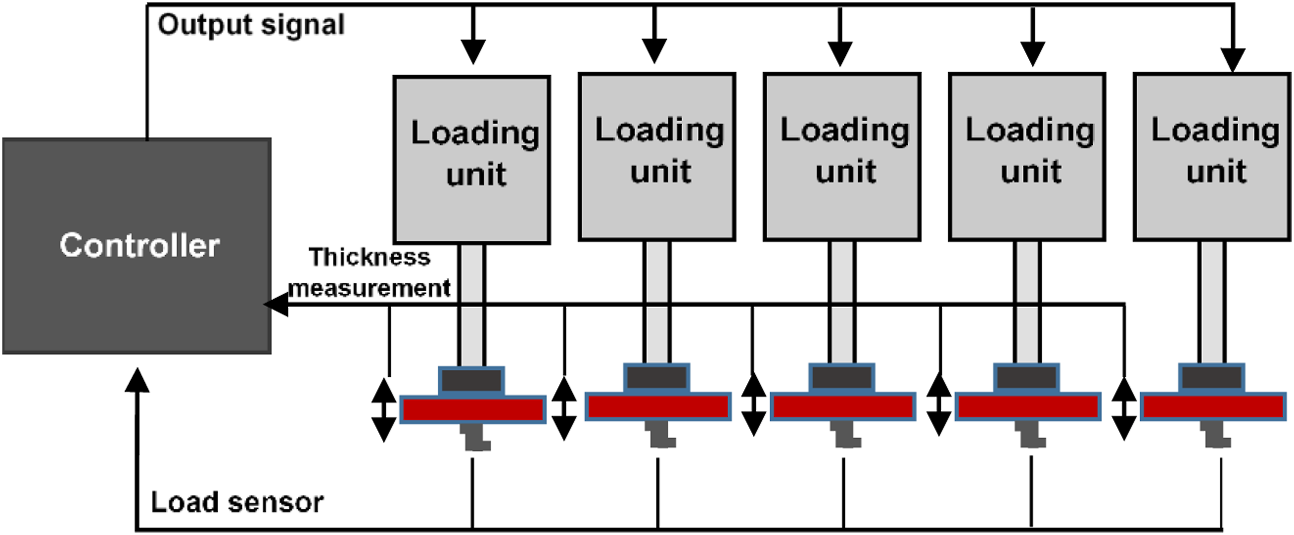
According to conceptual design of the test device, the design specifications were determined to solve difficulties encountered in carpet tests. The design specifications are; • The device must be able to apply loading and unloading processes automatically. • The device must be able to apply loads of 2kPa, 220kPa and 700kPa. • The device must be able to apply the load with a sensitivity of 0.2kPa. • Thickness measurement must be carried out with a precision of 0.01mm. • The device must have presser foot with a circular area of 300–1000mm2 in accordance with international standards. • The device must have a control unit. • The device must have a PLC software that applies the test procedures according to the standards. • The applied load must be distributed to the carpet homogeneously. • The pressure foot must be raised up and lowered down uniformly. • The device must have 5 test units. • The device must have an ergonomic structure. • The device must have a user-friendly interface.
Design of prototype test device
For the test device developed in this study, advantages and disadvantages of different systems were evaluated. In accordance with the working principle of the device, servo motor control, hydraulic systems, and pneumatic systems were examined in detail. In case of the servo motor usage for loading unit, a gearbox is required to adjust the required loads. Design and manufacture of a gearbox is complex and expensive. Hydraulic system was also evaluated as a solution alternative. According to the comparison of hydraulic system with pneumatic system, it was revealed that the control of the hydraulic system will be more difficult and slower than pneumatic system. Low level of load application as is essential for carpet thickness measurement. It is more difficult to obtain 2 kPa load value by using a hydraulic system compared to a pneumatic system. Also, more equipment is needed in hydraulic systems. By considering these factors, it is proved that the use the pneumatic system will be very effective in controlling the amount of load to be applied, tracking interval and cost.
The properties of pneumatic system materials and PLC hardware materials used for the developed test device were decided. Pneumatic cylinders (Q25-100 mm), positioning sensors, proportional pressure regulators, valves, filter regulators, connection equipment are the basic materials of the pneumatic system. PLC hardware equipment consists of analog-digital module, load cell, Liquid-Crystal Display(LCD) panel. Since the developed test device is a 5-unit system, 5 of each PLC automation materials were used. A piston cylinder with a diameter of 25 mm, a maximum pressure capacity of 1 MPa and a stroke capacity of 100 mm was selected in order to create the pressure required in the standards. To control the applied load, an S-type load cell with a maximum measurement capacity of 50 kgf and a measurement accuracy of 0.001 kgf was used. Position sensor used for thickness measurement was placed on the piston cylinder block and the movement of the presser foot was followed. The position sensor has a measurement capacity of 100 mm and measurement precision of 0.01 mm. Therefore, the thickness measurement was made with a sensitivity of 100 mm ± 0.01 mm.
The loading unit frame design and dimensions were determined according to the loading conditions, dimensions of the pneumatic cylinder, load cell and the carpet sample. When the maximum load condition of the test device is considered, it is decided that the metal frame of the system must withstand a 700 kPa load without deflection. On the other hand, for prolong heavy static loading test, 700 kPa load is applied to the carpet sample for 24 hours. For this reason, metal rod pieces were placed on the diagonals of the unit in order to distribute the applied load to the lower plate (Figure 2). The piston cylinder is placed in the middle of the upper plate. A curved structure was created on the lower and upper parts of the test unit to prevent deflection that may occur due to high load on the material used for the plate. Thus, it is ensured that the amount of load to be applied to the carpet sample in each unit is distributed uniformly and in a controlled manner. While designing the unit, the distance between the piston cylinder and the carpet test sample was determined according to the stroke (100 mm) characteristic of the piston cylinder. In this device, the distance between the pneumatic cylinder and the sample placement section is set as 40 mm. All design drawings were obtained using the SolidWorks software. All components of the test unit are given in Figure 2 in detail. Frame of carpet test unit and layout of equipment.
Manufacture and construction of the test device
After the drawings made in the SolidWorks program, the suitability of the drawings was controlled. The compatibility of the parts was controlled, and they are assembled in computer environment. The necessary arrangements were made. Then, the checked parts were manufactured in accordance with the drawings. All parts were produced using relevant manufacturing methods (laser cutting, Computer Numerical Control (CNC), etc.) and they were tested according to tolerance and fit limits. Firstly, the main frame and parts of test unit were manufactured. Later, the pneumatic system equipment, PLC control system hardware parts and LCD panel were constructed on the test device and the whole assembly phase of the test device was completed (Figure 3). The pneumatic system equipment is shown in detail in Figure 4. In addition, PLC unit, which contains the electrical connections and control modules of the device, and compressor are located on the side of the device as a separate unit. Photographic view of developed carpet test device. Layout of pneumatic system materials and appearance of test unit.

According to operation principle of the test device, the necessary signals are sent to the valve and proportional pressure regulator adjusts the amount of the pressurized air sent to the pneumatic cylinder and duration of application with PLC system. By this way, the load required in the standard is applied for the required time and the load is removed at the end of the relevant period. In order to apply the target load value on the carpet specimen, a load cell is joined under the plate where the carpet sample will be placed. The load cell gives feedback about the amount of load applied to the carpet sample. By this way, it is controlled whether the desired load value is reached, and the load value will be kept constant for the entire loading period as well. The control unit continuously sends the appropriate commands to the proportional pressure regulator to reduce the difference between the set value and the actual value received from the load cell and so it is ensured that the load applied on the carpet sample remains constant at the desired value and for the desired period of time. The thickness of the carpet sample is measured with cylinder position sensor W/IO-link that is placed on the piston cylinder. The position sensor detects the motion of the piston cylinder with a 0.01 mm sensitivity. Between sensors and PLC control unit an Analog/Digital conditioning was used. The analog signals acquired from position and load sensors were converted to digital signals for processing in PLC control unit. The feedback signals generated by PLC control unit were converted to analog signal before sending to proportional pressure regulator. The thickness values of the carpet sample are measured among the test period and the thickness values corresponding to the specific instant that is defined in the related test standard will be saved and displayed on the screen. The thickness loss of the carpet sample is automatically calculated via PLC software and displayed on the screen as carpet resilience performance.
Experimentation
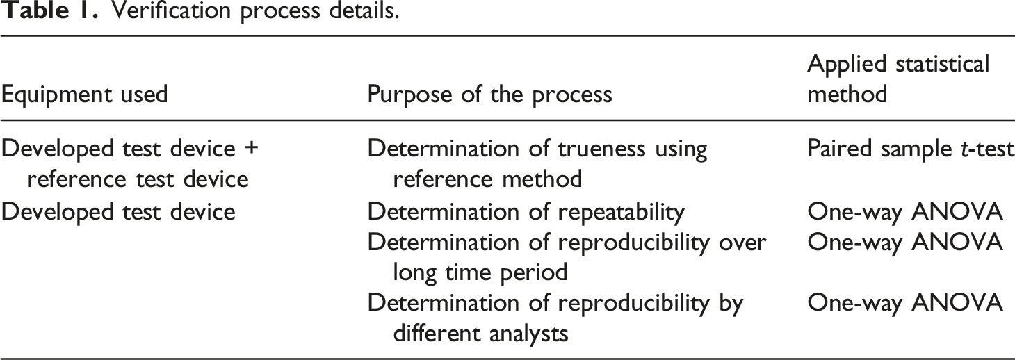
Verification is essential to prove the ability of the test device in terms of satisfying the required criteria in accordance with the international standards. The equipment, details of the verification process and the applied statistical methods were summarized in this section.
In this study, the applied load and its duration were measured and controlled by the control system elements and sensors (load cell). Thus, only the thickness measurement needs to be verified. The verification procedure of the test device was shown as a flowchart in Figure 5. Verification procedure of test device.
In the verification study for the thickness measurement procedure, the “accuracy” criterion has been taken into consideration. Accuracy criterion is stated by the determination of “trueness” and “precision.” For the determination of trueness, an available test device which is accepted as providing the true values is considered as the reference test device. Then, the measurements taken from both devices are compared statistically. In this study, 10 different randomly selected carpet samples were used. Five specimens with 10 × 10 cm dimension were cut from each carpet sample. The thickness measurements were taken by reference test device under 2 kPa as declared in the thickness measurement standard (Figure 6). Reference test device and carpet samples used for verification.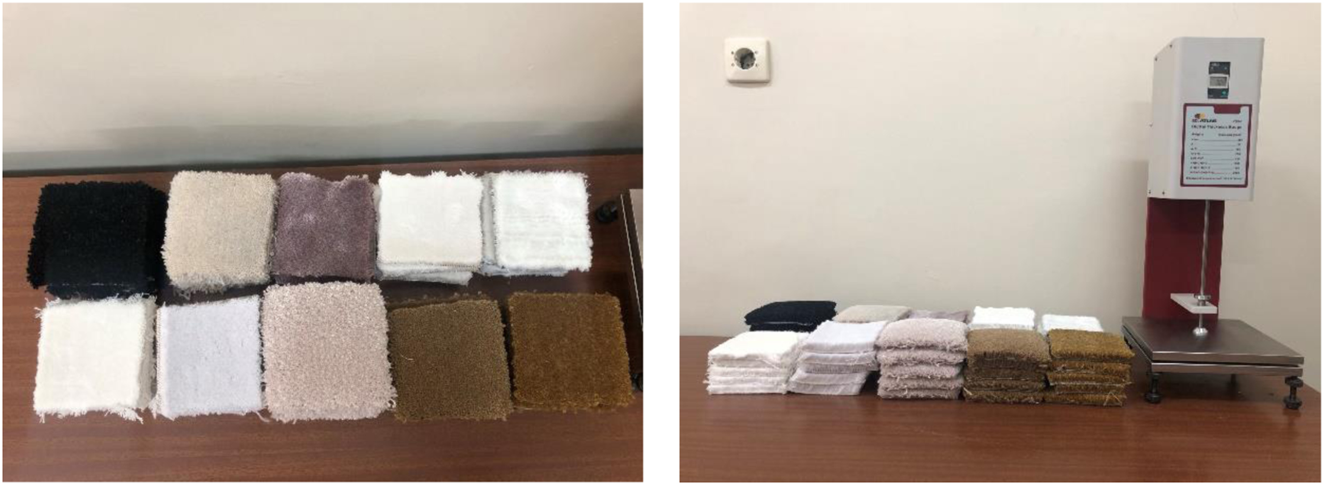
The same samples were subjected to thickness measurement by the same operator using the developed test device. Since the developed test device is a 5-unit system, trueness detection was made for each unit separately. Paired sample t-test was applied to the obtained data by using Statistical Package for the Social Science (SPSS) statistical package program. As a result of the analysis, it is concluded that the trueness conditions are satisfied if there is no statistically significant difference between the groups. Statistical analysis was done in 95% confidence interval.
For precision determination, repeatability and reproducibility criteria were taken into consideration. For repeatability, thickness measurements were taken by the same operator, 3 times in the same day with the developed test device. 25 test specimens were prepared from one carpet sample and 5 thickness measurements were taken from each unit. Thus, thickness measurement data were obtained to determine repeatability separately for each unit. Analysis of variance (ANOVA) was applied to the obtained data using SPSS statistical package program. As a result of the analysis, it can be concluded that the repeatability conditions are satisfied, if there is no statistically significant difference between the groups. Statistical analysis was done in 95% confidence interval.
Verification process details.
Results and discussion
The thickness measurement of the test device was verified on basis of trueness and precision criteria according to verification methodology. The results of the applied statistical analyses are given in detail.
Trueness determination
Thickness measurement values of samples for trueness determination.

Average, standard deviation and CV values of thickness measurements.


Average thickness values for developed and reference test devices.
The results of paired sample t-test.

T: Test Device Unit, R: Reference device.
Precision determination by repeatability
Thickness measurement results repeated in the same day.

The results of the normality test.

aThis is a lower bound of the true significance.
bLilliefors significance correction.
ANOVA result for three measurements repeated in the same day.

Precision determination by reproducibility
Thickness measurements taken in three different days.

The results of normality test for three different days.

aThis is a lower bound of the true significance.
bLilliefors significance correction.
ANOVA results of three different days.

Thickness measurement results with three different operators.

The results of normality test for three different analyst measurements.

aThis is a lower bound of the true significance.
bLilliefors significance correction.
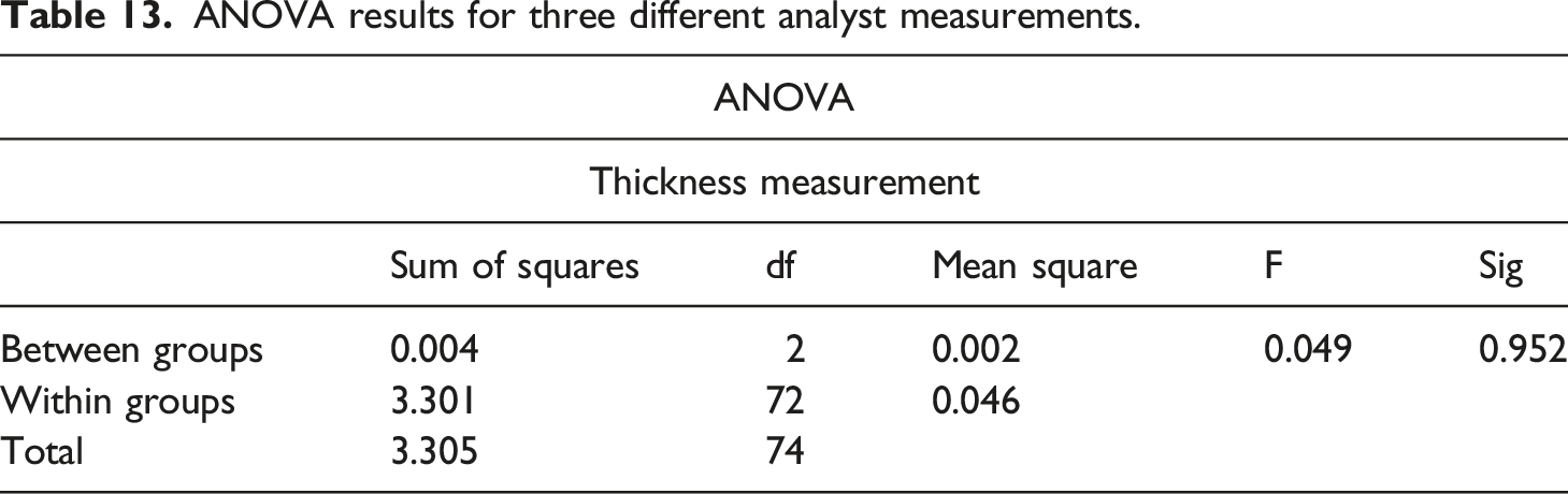
ANOVA results for three different analyst measurements.
Conclusion
This paper innovates an automatically controlled carpet resilience testing device. In this innovative design, the pneumatic system was preferred for application of the loadings and the applied loads was checked by load cells located under the sample holders for a precise load application. The thickness of the carpet samples was measured by position sensors located on the pneumatic cylinders. The proposed test device is capable of applying the required loadings while automatically controlling the loading and recovery periods of five samples. Test device is capable of storing the thickness measurements and calculating the thickness loss values. It can also perform simple statistical analysis and submit the results on a screen by its user-friendly interface. To prove the ability of the test device meets the international standards, verification of the proposed device was done by statistical methods. As a result of trueness determination, the Mean Absolute Percentage Error (MAPE) values of the developed test device were between 0.001–0.023, in comparison to that of the traditional carpet thickness tester, which exhibits very close trend between two measurements. The precision analysis results revealed no significant difference in 95% confidence interval between developed test device and the carpet thickness tester.
Consequently, the proposed test device can be regarded as system prototype demonstration in operational environment. Compressibility and resilience properties are important for bulky or high loft fabrics as well as carpets. The proposed system can be enhanced in the future by modifications to the application to test the various properties of the fabric.
Footnotes
Declaration of conflicting interests
The author(s) declared no potential conflicts of interest with respect to the research, authorship, and/or publication of this article.
Funding
The author(s) disclosed receipt of the following financial support for the research, authorship, and/or publication of this article: This study was supported by The Scientific And Technological Research Council Of Türkiye (TUBİTAK). Project Number: 119M691. We express our sincere thanks for their financial support.