
Abstract
Fiber reinforced polymers, especially carbon fiber reinforced polymers, are expected in the future to contribute more than 50% of the structural mass of an aircraft. With increasing application and experience increased attention is paid to carbon-fiber reinforced composites with improved advanced properties, such as mechanical, structural and electrical, allowing them to displace the more conventional materials, such as metal alloys. In this paper, we used the Design of experiment methodology to investigate the design and properties of newly developed unique porous carbon-fiber reinforced composites intended for electromagnetic shielding purposes. The main goal was therefore to fabricate a composite with low thickness, high permeability to air and water vapor with a satisfactory ability to shield electromagnetic fields, whereas the investigation of the influential variables of the reinforcement and the investigation of the influence of the matrix on the overall shielding efficiency of the composite belongs to the sub-objectives. Furthermore, other important properties of the composites including heat and mass transfer, mechanical and electrical properties were evaluated. A quality index evaluation approach using weighted and normalized data was implemented to choose a composite with properties, which best fits to its intended use. The highest quality index was achieved by the composite containing reinforcement with warp and weft sett 18 dm−1 using carbon tape 2 mm wide. This composite provides electromagnetic shielding 36 dB at 1.5 GHz, having high air permeability 1000 mm/s, relatively low bending rigidity of around 2.5 Nmm and thickness of only 0.37 mm.
Keywords
Introduction
Carbon fiber reinforced epoxy composites are very often used in the avionics industry now. The aeronautical industry has replaced classic flight instrumentation with electronic equipment making it more vulnerable to its electromagnetic environment. Lightning and high intensity radiated fields both within the aircraft (onboard avionics or passenger mobile phones) and external to the aircraft representing this environment are met in a regular flight service with a given probability. Strong and variable external electromagnetic fields may penetrate into the fuselage and the internal wiring installations, causing interfering and possibly destructive voltages and currents that may endanger vulnerable airborne equipment. 1 That is why there is an increasing demand to not only reduce aircraft weight using innovative materials, but also provide advanced properties such as reliable mechanical properties combined with a high level of electromagnetic interference shielding ability. 2
Electromagnetic interference shielding is a technique of creating a barrier that prevents leakage of strong electromagnetic fields that can interfere with sensitive electronic devices or signals. At the same time, it represents an electromagnetic shell made of the shielding materials (electrically conductive or magnetic), which forms a close region and shields incoming electromagnetic wave, wheareas reflection, absoption and attenuation are the main mechanisms to reduce the effects of electromagnetic field of the radiation sources. 3 Electromagnetic shielding effectiveness (SE), usually expressed in decibels (dB), is a measurement of the attenuation of an electromagnetic signal through the shielding material, and it is commonly used to evaluate the performance of this material.
In addition to traditionally used metal sheets, carbon fiber (CF) reinforced polymer composites are now preferred for electromagnetic shielding applications, mainly due to their low density. The CF is electrically conductive due to the planar layered structure of carbon atoms. 4 Previous studies 5–11 confirmed that concentration, orientation, electrical characteristics, and aspect ratio (the ratio of length to diameter) of discontinuous CF are the determining parameters for the level of the electromagnetic shielding ability of the composite. However, the randomly dispersed discontinuous CF does not have to provide a sufficiently continuous conductive network. That is why the most practical method of producing a conductive network with fillers at a low concentration is to use continuous carbon fibers (CCF). It has been reported that composites with CCF show better electromagnetic shielding efficiency than those with discontinuous CF. As described in 12 , the mean SE over the whole measured frequency range of polymer-matrix composites with CCF was about 115 dB and that of polymer matrix composites with discontinuous CF was about 98 dB. The dominant mechanism of electromagnetic shielding effectiveness of CCF composites is through reflection.4,13 This is the reason why woven CCF were used to construct a predesigned conductive network as a composite reinforcement in this paper.
The preparation and characterization of continuous CF-reinforced composites have been reported in several studies.4,12–21 If we focus on the SE ability of the CCF composites, the literature review revealed that to obtain a fabric with a high capacity to shield electromagnetic field, it is advantageous to use continuous, highly electrically conductive CFs, with the plain-weave-type being the preference. For example, CCF laminated composites were studied in terms of their ability to shield the electromagnetic field in. 16 An excellent SE (more than 80 dB) was achieved by a composite slab made of four layers of prepregs 3 mm thick, whereas the reflection mechanism is dominant. Another paper 19 describes SE evaluation and prediction of CCF laminate, providing SE around 70 dB for frequency 12 GHz and having thickness around 1 mm. As described in 4 , the woven CCF composite’s SE depends on the weave type, the number, and the angle of overlapped plates. It was found that the SE of the single, double, and triple plain and balanced-twill woven CCF composite plates was 50 dB, 60 dB, and 70 dB, respectively. The authors mainly focus on mechanical properties and electromagnetic shielding ability; however, less attention is generally paid to the structure of the CCF composites, especially in terms of porosity and air/moisture permeability. Despite the important fact that the development of flexible air/water vapor permeable composites designed for shielding the electromagnetic field has received increasing attention in recent years. This is because the porosity and the associated air permeability can be one of the important requirements, especially with regard to the removal of generated heat from important aircraft electronic equipment.
It should be mentioned that some approaches have been found to manufacture porous carbon films or CF reinforced composites,22–25 but these approaches do not consider electrical conductivity or electromagnetic shielding of the structure. They are fabricated for thermal protection, gas separation, purification, or liquid phase processing.
All the above research indicates the need for exploration of electromagnetic shielding of lightweight, low thickness CCF woven reinforced composites in terms of their structure, especially the porosity and heat and mass transfer. With this in mind, the current research builds on the findings already published by the authors in the paper 26 and aims to fabricate an epoxy composite with low thickness, high permeability to air and water vapor and with a satisfactory ability to shield electromagnetic fields, whereas the investigation of the influential variables of the reinforcement and the analysis of the influence of the matrix on the overall shielding efficiency of the composite belongs to the sub-objectives of this study. Design of experiement methodology was used to investigate the design and properties of newly developed unique porous carbon-fiber reinforced composites made of Aksaca electrically conductive CCF tapes intended for electromagnetic shielding purposes. Eleven composite samples were prepared in total with a different sett of warp and weft threads and different thread thickness of the plain weave CCF reinforcement. To maintain low thickness, high porosity, and flexibility of the composites, carbon fiber woven fabrics reinforcements were only impregnated with epoxy resin, which endows composite mechanical robustness by stabilization of binding points. The main attention was paid to the electromagnetic shielding ability of the composites measured by the ASTM D4935-18 standard. Furthermore, other important properties of the composites such as thickness, density, thermal conductivity, thermal resistivity, air permeability, the ultimate mechanical properties, bending rigidity and electrical properties represented by elecrical resistivities and relaive permittivity were evaluated. Finally, a Quality index evaluation approach using weighted and normalized data was implemented to choose a composite with properties that best fit its intended use.
Geometrical structure of multifilament tapes
Carbon multifilaments in the form of prepreg tapes are increasingly used in high-performance composites. The advantages of using carbon multifilament tapes with a rectangular cross-section over threads (rovings) with a circular cross-section (see Figure 1) include the following: (a) constant thickness and width, (b) reduced thickness compared to rovings, (c) evenly distributed tensile stress.
27
Assuming that the tape consists of carbon fibers of circular cross section of diameter d, two packing arrangements can be considered; open packing and hexagonal close packing.
28
Close packing is one of the basic forms of packing models in which the filaments fit into a hexagonal pattern as illustrated in Figure 1 and its maximum value is 0.785. Close packing has been analyzed over the last few decades, for example in papers.29–31 The geometry of a carbon (a) roving and (b) tape.
Carbon roving with the fineness T [tex] composed from individual carbon filaments with fineness t [tex] has a total number n [-] of filaments
Diameter D [mm] of the carbon roving with the circular cross-section can be estimated as

When flattening the carbon roving having diameter D due to the position of the fibers, it is assumed that the fibers are not deformed. The assumption is that the multifil flattens from the original circular cross-section to the so-called Kemp’s cross-section, which is rectangular with semi-circular ends.
33
The width of the multifilament a with a rectangular cross-section is increased, followed by a decrease in thickness b. The a and b parameters are changed depending upon the number of layers l
n
[-].
32
Relative width α and relative thickness β, and relative flatness γ
There are two types of geometrical assumptions (based on constant area or constant circle circumference) when predicting the relation between relative width and relative thickness. 32
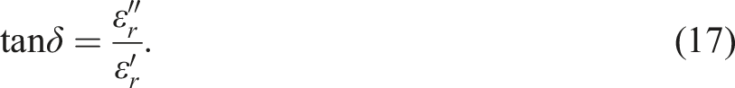
Electromagnetic shielding effectiveness
The electromagnetic shielding effectiveness (SE or SE
T
) of a material is defined as the ratio of the transmitted power to incident power and is expressed in the form of Diagram of electromagnetic wave attenuation when passing through a material, where R, and T are reflection and transmission components, respectively.

Scattering parameters S11* (or S22*) and S21* (or S12*) in [dB], which are obtained by measurement using a two-port network analyzer, give the reflection (R), transmission (T), and absorption (A) components [-], where


The significance of reflection and absorption components can also be expressed as a portion of reflection (R) or absorption (A) to not transmitted energy (1-T) expressed in [%] or [dB]


Quality index evaluation
According to,
34
quality means fitness for purpose. In other words, whatever is produced – a good or service – it must fit its purpose. To be fit for purpose, every good and service must have the suitable properties to satisfy customer needs and must be carried out with only a few failures. A quality index QI was chosen to evaluate the total performance of the fabricated composites. In the first step, the broken line function is constructed to estimate quality grade u
i
(x) ( Diagram of utility grade u
i
(x) construction.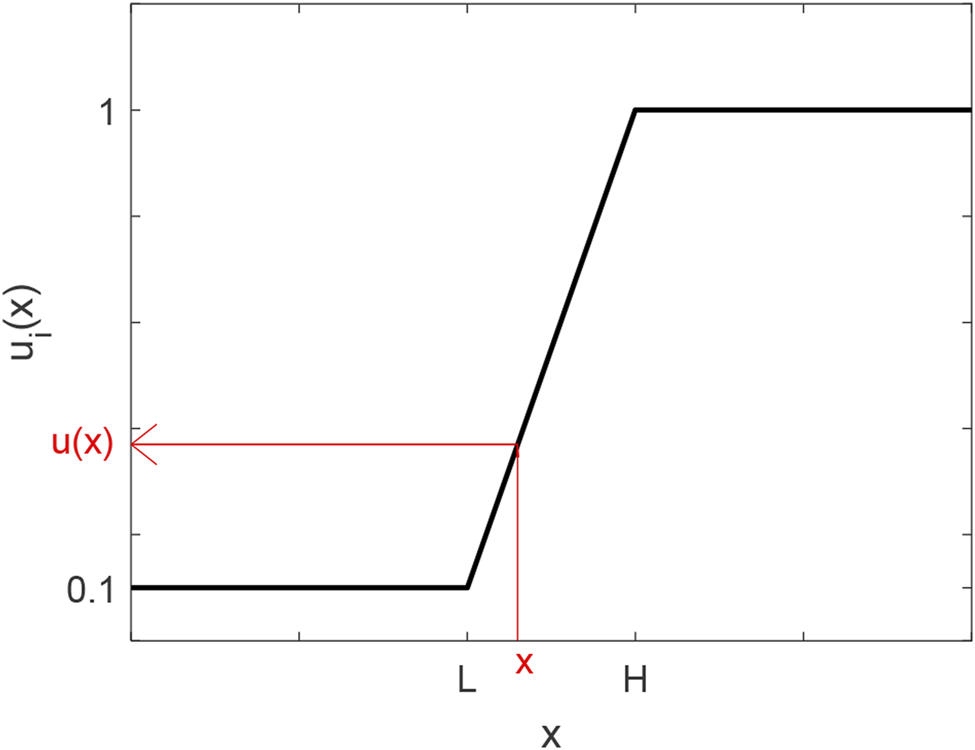

Based on the quality grade of all essential features that were singled out as pivotal, the quality index QI (

Materials and methods
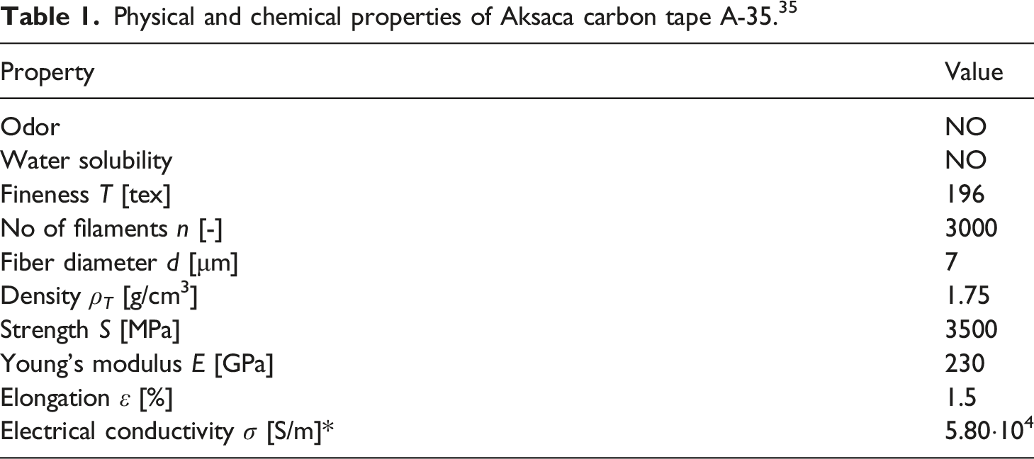
Continuous carbon-fiber tape
Physical and chemical properties of Aksaca carbon tape A-35. 35
Geometrical properties of Aksaca carbon tape A-35.

Carbon-fiber woven reinforcements
Input variables, units and levels.

Main properties of the carbon-fiber woven sample set.

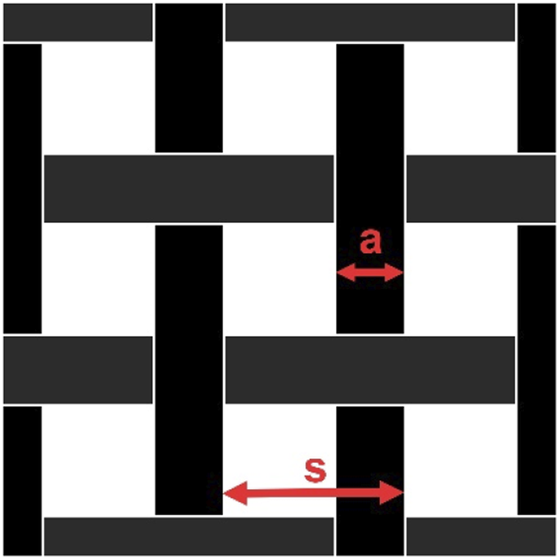
Diagram of carbon tape woven fabric having plain weave with different settings such as carbon tape spacing s and carbon tape width a.
These specific spacings of warp and weft threads were chosen regarding the carbon material consumption and the air and water vapor permeability of woven structures often required for the final application. The sample with the lowest warp and weft sett had five threads per 100 mm, corresponding to a 20 mm carbon tape spacing (s, see Figure 4) in both the warp and weft. Meanwhile, the densest sample reinforcement was 100 threads per 100 mm.
Carbon-fiber woven reinforced composites
Epoxy resin EPIKOTETM MGS LR285 (ρ
ER
= 1200 kg/m3, η
ER
= 600–900 mPa.s) and hardener 500 (ρ
H
= 1030 kg/m3, η
H
= 200–350 mPa.s) was used to manufacture composites.
37
Epoxy and hardener were firstly mixed using a mixing ratio: 100:40 (by weight) by magnetic stirring at room temperature for 5 min. Textile reinforcements were impregnated by a mixture of epoxy and hardener assisted by vacuum infiltration at room temperature for 24 h, and then treated by curing at 60°C for 15 h. Images of carbon woven fabric reinforced composites representatives are shown in Figure 5 using an HP ScanJet Pro 2500 f1. Images of selected samples in the set: (a)–(e): sample 1–5, (f) sample 8, (g) sample 11.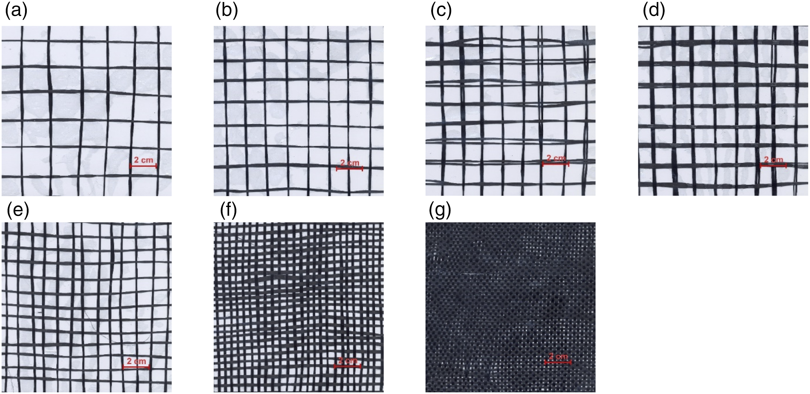
Vacuum infiltration was applied using a flexible vacuum bag system. The initiated epoxy resin was manually applied over the entire sample area using foam rollers. After uniform application of the resin, the vacuum bag system was closed and the pressure (p = 600 mbar) was applied to ensure uniform application of the resin over the entire sample area. Redundant matrix was aspirated using pressure through the perforated bottom film into the suction layer formed by the non-woven fabric. Inter-thread pores were completely filled with the resin in case of samples having very low spacing of carbon tapes (sample 11). The inter-thread pores remained almost free - containing air in case of samples with higher carbon tape spacing (sample 1 – 10). Microscopic details of pores of chosen samples are shown in Figure 6, whereas light gray color represents matrix and the black color is black background. Images were captured by PROMICAM 3-5CP Digital Camera. Size of images is 1224 × 1024 px (1 px = 19.4 μm). Microscopic images of inter-thread pores of: (a) sample 7, (b) sample 10.
This type of epoxy was chosen due to hydrophilic character of the laminating resin system, advantageous mixing viscosities adjusted such that the resin will not run out of wide-meshed fabrics on vertical surfaces. The used epoxy system meets the standards for gliders and motor gliders. Due to its excellent physiological compatibility is the most commonly used system in the aerospace industry today.
Epoxy impregnation along with CF fabric reinforcing can endow composite mechanical robustness (mechanical stability of pure woven reinforcement, especially with high carbon tape spacing, is poor) as well as retaining especially flexibility and porosity of the carbon woven fabric reinforced composite.
Methods of measurements
To measure 


The derived relations apply to an ideal composite material without cavities. It is possible to express the volume fraction of cavities V
cav
by the following equation
The setup consisted of a sample holder with its input and output connected to a network analyzer. An SE test fixture (model EM-2107A; Electro-Metrics, Inc.) was used to hold the sample, with the design and dimensions of the sample holder following the standard method noted above. The measured sample was in the shape of a circle with a diameter of 13.31 cm. To generate and receive the electromagnetic signals, we used a Rohde & Schwarz ZN3 network analyzer, while the insertion–loss method was used to determine the SE of the fabric. The samples were air-conditioned prior to testing (T = 23 ± 3°C, RH = 50 ± 10%), with the measurements performed (n = 5) at five different randomly chosen sample locations to facilitate the subsequent statistical analysis.

Results and discussion
Basic physical properties of the carbon tape reinforced composites
Physical properties of composites.

Analysis of the electromagnetic shielding effectiveness of the carbon tape reinforced composites
This evaluation aimed to determine the effect of the two factors mentioned above on the resulting electromagnetic shielding ability of the composite. Another goal was to find out how the SE of composite changes due to epoxy impregnation compared to the SE of the reinforcement itself.
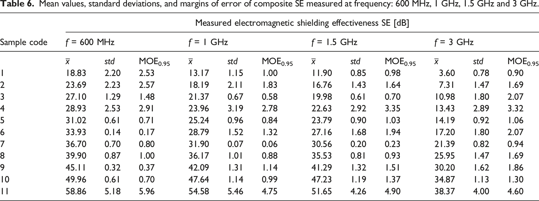
Mean values, standard deviations, and margins of error of composite SE measured at frequency: 600 MHz, 1 GHz, 1.5 GHz and 3 GHz.
Analysis of variance for the factorial design.

Here, it was clear that both factors, Spacing and carbon tape Width, were statistically significant since all of the p-values were below the significance level (α = 0.05). Meanwhile, a two-factor interaction was also significant. The main effect of Spacing dominated this process, accounting around 87% of the total variability, while the main effect of Width accounted around 12% and the percentage contribution of the interaction was ∼1%. It was confiremed that Spacing corresponding to warp and weft sett of woven fabric was the main influencing factor in this case which was expected and this finding is consistent with published results in the field of electromagnetic shielding fabrics development.18,49–51 In addition, decreasing the Spacing by one level while keeping other variables constant increases the carbon roving area by 100%, while increasing the roving thickness by one level increases the area of electrically conductive material by only 59%. A normal probability plot of the residuals and the other usual diagnostics indicated that both the normality and the constant variance assumptions were met. The spacing–width plot is shown in Figure 7, with the main effect plots indicating that variable Spacing had a negative main effect, i.e., an increase in the variable moved the electromagnetic SE downward, while variable Width had a positive main effect. Overall, the main effect of the spacing was higher than that of the width. Dependence of SE on: (a) carbon tape spacing and (b) carbon tape width forming the weft and warp threads in the composite structure.
The regression model that describes this experiment (first-order model with interactions) can be written in the following form

Figure 8 shows the case’s three-dimensional response surface and the contour plot. It should be mentioned that the simplest possible model was chosen, which adequately describes the experiment with a relatively high coefficient of determination (R2 = 0.97). The response surface graph for dependent variable SE (f = 1.5 GHz).

Error between measured and predicted SE data (f = 1.5 GHz).

As Table 8 shows, r < 5 for all samples except for the sample 11 which confirms the suitability of the proposed model, especially taking into account the fact that the random error of the coaxial transmission line method, as reported in the standard (see Ref. 40 ), is ±5 dB.
The obtained model (Eq. (19)) could also be used to create a graphical representation of the experimental region. The resultant response-surface contour plot (Figure 8) indicates how the response related to two continuous design variables behaves. Here, it was clear that the higher the carbon tape width and the lower the carbon tape spacing (i.e., higher warp and weft sett), the higher the SE.
Effect of carbon tape spacing and carbon roving width on the SE of composite
Figure 9(a) shows the dependence of the mean SE values on the frequency for samples 1, 2, 5, 8, and 11, with the shading around the mean values indicating their 95% intervals. Here, it was clear that the SE decreased slightly with an increase in frequency (decreasing wavelength) for all the samples, which was in accordance with the theoretical assumptions. It should be noted that the lowest examined frequency (30 MHz) corresponded to a wavelength of 10 m, while the highest measured frequency corresponded to a wavelength of 0.1 m, meaning the longest aperture dimensions of all samples was small (L <28 mm) concerning the wavelength of the electromagnetic wave for the entire studied frequency range. It was also observed that the wider the carbon thread spacing s (the lower the aperture dimension L), the lower the SE ability of the sample. The sample with the lowest warp and weft sett was found to have the lowest SE (SE = 12 dB for f = 1.5 GHz), while that with the highest warp and weft sett had the highest SE (SE = 52 dB for f = 1.5 GHz) comparing samples having carbon tape width a = 2 mm. Figure 9(b) shows the dependence of the SE on the carbon tape spacing s at a particular frequency, i.e., 1.5 GHz, where, with an increase in s, the SE behavior was more visible. The solid line in this figure represents the data approximation using an exponential function with a high coefficient of determination (R
2
= 0.99). It should be noted that the specific spacing of the carbon threads, or the sett of the warp and the weft of the fabric, must be chosen in view of the requirements of the final application. Dependence of SE on (a) frequency and (b) carbon tape spacing (f = 1.5 GHz) for samples 1,2,5,8 and 11.
Figure 10(a) shows the dependence of the SE on the frequency for samples 2, 3, and 4, i.e., those with different widths of carbon tape in their warp and weft threads (s = 15 mm). Again, it was clear that the SE decreased slightly with an increase in frequency and that this was distinct over the entire frequency range, i.e., the greater the number of tapes forming the warp and weft threads, the greater the SE. Meanwhile, Figure 10(b) shows the relationship between the SE and carbon tape width making up the warp and weft threads for the frequency of 1.5 GHz, which could be approximated using a logarithmic function with a very good fit (R
2
= 0.99). The same behavior was also observed with the other sets of samples (s = 10 mm, s = 5 mm) having different widths of carbon tape making up the warp and weft threads. Dependence of SE on (a) frequency and (b) a number of carbon tapes (f = 1.5 GHz) for samples 2, 3, and 4.
In Figure 11(a), there is a comparsion of SE of all sample set for the frequency 1.5 GHz, which corresponds to the behavior of composites described above. (a) Comparison of SE for all sample for f = 1.5 GHz, (b) SE throught absorption and reflection for sample 9.
Furthermore, the mechanism behind the shielding ability of the prepared carbon reinforcements intended for the formation of composites was investigated in terms of the chosen sample set. The SE effectiveness through absorption (SE A ) and reflection (SE R ) was calculated (in dB) based on the measured scattering parameters S 21 and S 11 according to equations (4)–(6), and (8) for chosen sample no. 9 (s = 5 mm, a = 4 mm) with the results presented in Figure 11(b). When comparing the mean values of SE A and SE R over the entire frequency range, it is visible that SE A was the dominant mechanism for very low frequencies (f < 80 MHz), while at higher frequencies, SE R was the main contributor to the SE.
Effect of epoxy resin impregnation on the SE of composite
As mentioned above, one of the aims of this study was to find out how the applied epoxy resin affects the shielding ability of the composite. That is why SE of composite and reinforcement were compared for all samples and all frequencies; see frequency-dependent SE graphs in Figure 12 for chosen samples. It is visible that composite SE is relatively close to the SE of reinforcement for f > 1 GHz. The composite appears to have a higher shielding ability for f < 1 GHz compared to the SE of reinforcement alone. To objectively evaluate the positive effect of impregnation using epoxy resin on SE, i. e to determine if there is a significant difference between the means of two groups (reinforcement, composite), two-sample t-test was realized for all sample’s SE at selected frequencies (600 MHz, 1 GHz, 1.5 GHz, and 3 GHz). Null and alternative hypotheses are as follows Comparison of SE of composite and reinforcement itself for (a) sample 1, (b) sample 7, and (c) sample 11. The result of two-sample t-test. SEM images the composite fracture at the binding point with magnification (a) 500 × and (b) 1000 ×.


Air permeability and thermal properties
Mean values, standard deviations, and margins of error for composite air permeability A p , thermal conductivity λ, and thermal resistivity RT.
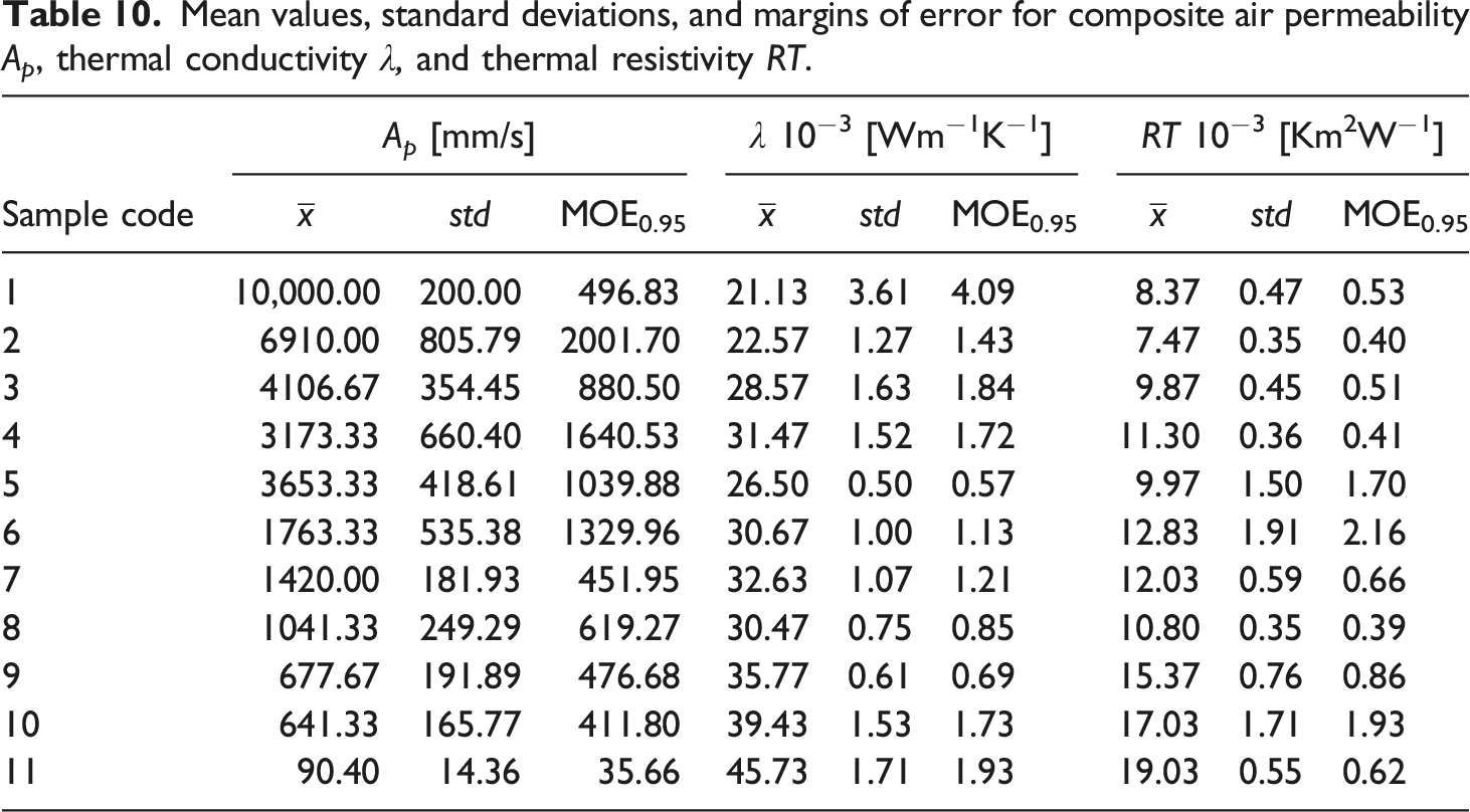
Air circulation and moisture vapor transport are frequently emerging requirements for composite structures. When evaluating air permeability A
p
, it can be seen (Figure 14(a), Table 10) that air permeability is decreasing strongly with decreasing spacing between carbon tapes forming the warp and weft of the woven reinforcement and ranges between 100 – 10 000 mm/s. As expected, the decrease in air permeability can also be observed with increasing carbon tape width while maintaining the same spacing. Comparison of (a) air permeability, (b) thermal conductivity, and thermal resistivity for all samples.
An increase in the content of the conductive component in the unit volume of the sample also positively affects the thermal conductivity of the sample, which is in accordance with the theoretical analysis. The smaller the content of well-thermal insulating air in the sample, the higher its thermal conductivity; see Figure 14(b) and Table 10. It can also be seen from the performed analysis that the thermal resistance increases with the increasing content of carbon tape in the composite sample, which is probably caused by the increasing thickness of the sample, see Figure 14(c) and Table 10.
Mechanical properties
Mean values, standard deviations, and margins of error for composite breaking force F, breaking elongation ε b, and bending force Fm.
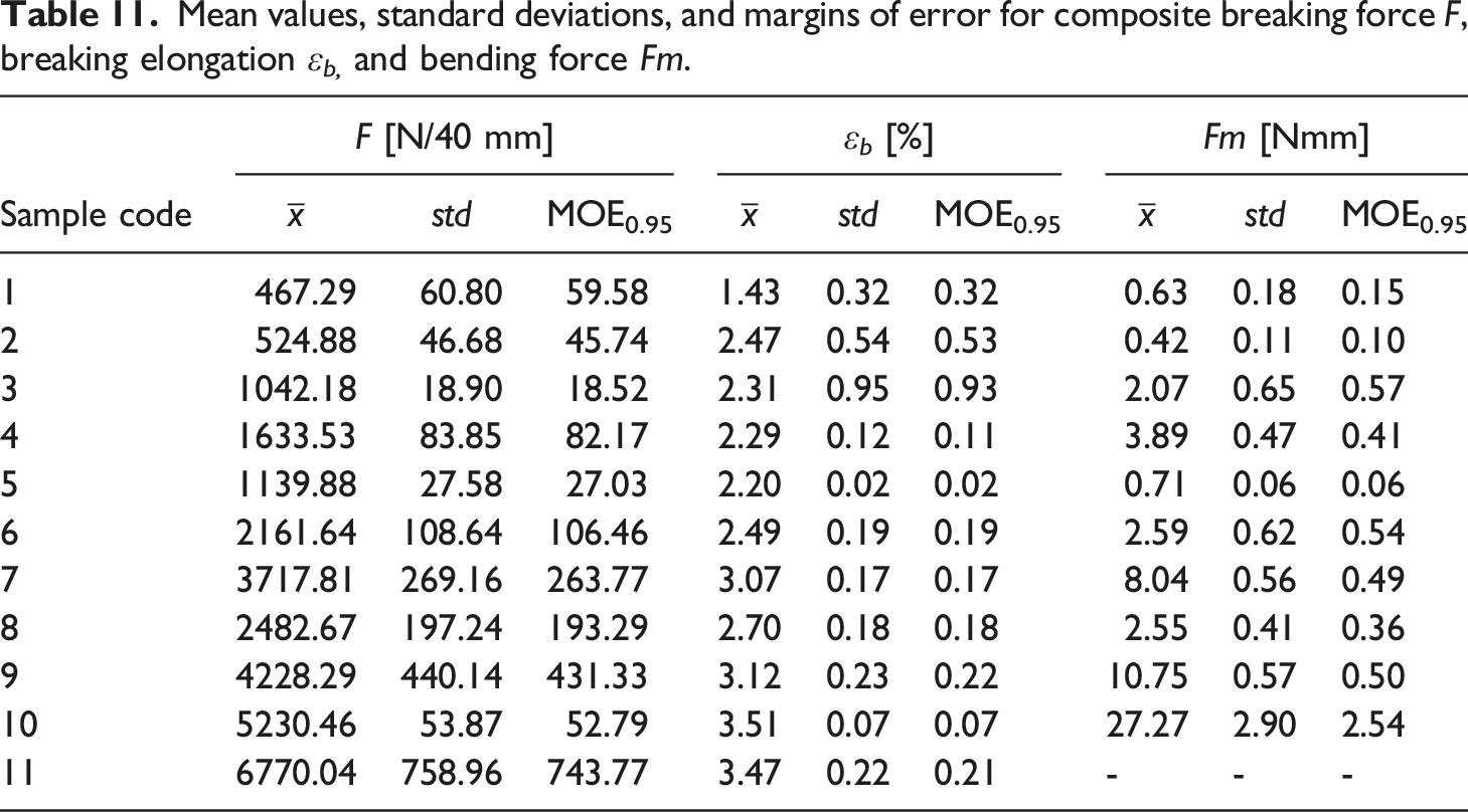
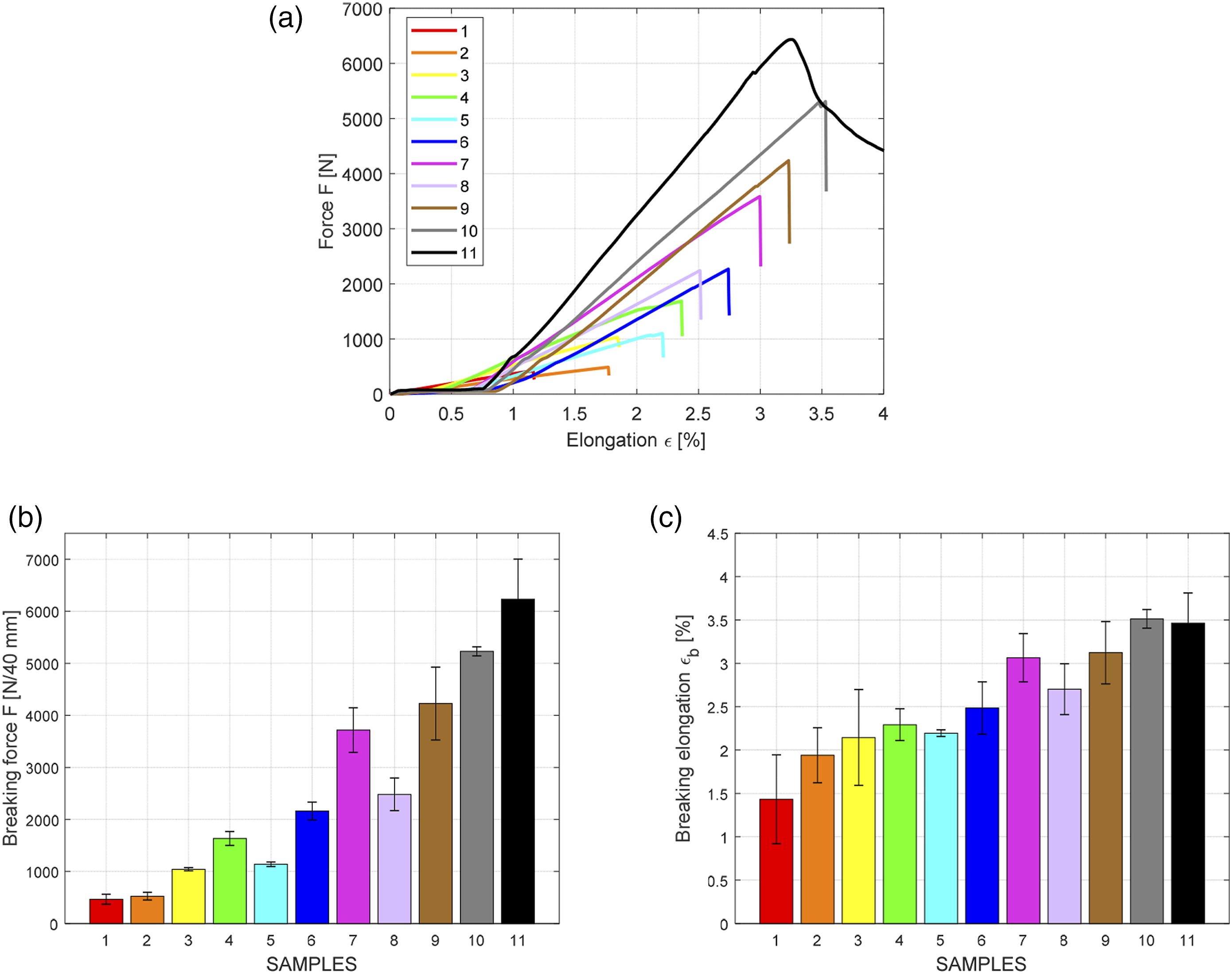
(a) The tensile force displacement curves; comparison of (b) breaking force, (c) breaking elongation for all samples.

(a) The bending force dispacement curves, comparison of (b) bending force for all samples.
Electrical properties
The electrical conductivity and permittivity of the reinforcement itself and the composite will be disucussed in this subchaper. In addition to other composites evaluations, the electrical conductivity, more precisely the surface and volume resistivity of the carbon reinforcement and the composite, were also compared. Sample 5 was chosen for this comparison. The comparison shows that the application of a non-conductive matrix causes a significant (by several orders of magnitude) increase in both resistivities, see Figure 17(a). However, this does not affect the electromagnetic shielding ability in any way, as it was demonstrated during the SE analysis. The matrix ensures the necessary robustness and mechanical endurance of the sample and does not impair the shielding ability of the composite. Figure 17(b) also compares the permittivity of the reinforcement and the composite for sample 5. Comparison of (a) electrical resistivity, (b) permittivity for reinforcement, and composite for sample 5.
Quality index evaluation
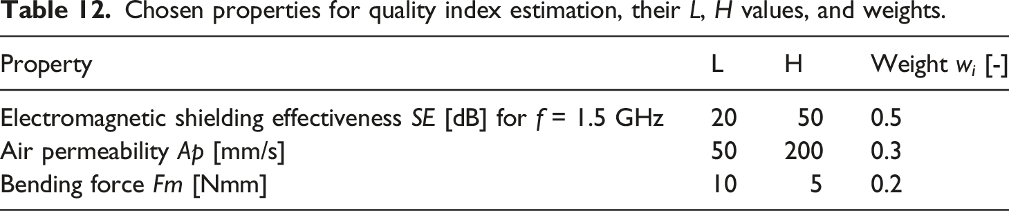
Chosen properties for quality index estimation, their L, H values, and weights.
Quality index including ranking (high to low) for the whole sample set.

Conclusion
In this paper, we introduced porous and low thickness CCF reinforced epoxy composites with excellent flexibility and superior electromagnetic radiation protection. A total of eleven composite types were manufactured using plain-weave reinforcements made of carbon tapes (fineness of single carbon tape T = 196 tex) for the weft and warp threads. The samples differed in the two following respects of the reinforcement structure: warp and weft sett (spacing between threads) and warp and weft thread thickness (by combining two and three carbon tapes). To maintain low thickness, high porosity, and flexibility of the composites, CCF woven fabric reinforcements were only impregnated by epoxy resin, which endows composite mechanical robustness by stabilization of binding points. Using this simple approach, reinforcing CCF fabrics can be easily impregnated with matrix materials that are not easily obtainable in the form of prepregs to get composites for advanced application.
Composites with a density ranging form 0.2 – 0.6 g/cm3 were prepared; having a thickness from 0.2 to 0.96 mm. Manufactured composites showed shielding ability of 12–52 dB at 1.5 GHz, whereas the main effect of the carbon tape spacing was higher than that of the carbon tape width. As predicted, the higher the spacing, the lower the SE. It was found that impregnation of the CCF reinforcement with an epoxy matrix does not have a statistically significant effect on the SE of the composite. In addition, it was found that the dominant mechanism of SE for polymer-matrix CCF composites is reflection. The spacing of carbon tapes had a negative effect (an increase in the variable moved the dependent variable downward) on breaking strength and breaking elongation. In contrast, it had a positive impact on air permeability, bending rigidity and thermal properties.
The composite containing reinforcement with warp and weft sett 18 dm−1 using thread 2 mm wide achieved the highest quality index. This composite provides electromagnetic shielding of 36 dB at 1.5 GHz, having a high air permeability of 1000 mm/s, relatively low force rigidity around 2.5 Nmm, and thickness of only 0.37 mm.
The chosen manufacturing process readily applies to reinforcing CCF fabrics with relatively low warp and weft sett, where binding points displacement is a limiting factor, and it represents a significant advantage over prepregs. Using this approach, low-cost, porous CCF woven reinforced composites that are permeable to air and water vapor with the desired SE can be designed and obtained for various applications in the aircraft industry.
Footnotes
Declaration of conflicting interests
The author(s) declared no potential conflicts of interest with respect to the research, authorship, and/or publication of this article.
Funding
The author(s) disclosed receipt of the following financial support for the research, authorship, and/or publication of this article: This work was supported by The European Union - European Structural and Investment Funds in the frames of Operational Programme Research, Development and Education - project Hybrid Materials for Hierarchical Structures and Ministry of Education Youth and Sports of the Czech Republic - project Hybrid Materials for Hierarchical Structures (HyHi, Reg. No. CZ.02.1.01/0.0/0.0/16_019/0000843).