
Abstract
Fabric draping, which is referred to as the process of forming of textile reinforcements over a 3D mold, is a critical stage in composites manufacturing since it determines the fiber orientation that affects subsequent infusion and curing processes and the resulting structural performance. The goal of this study is to predict the fabric deformation during the draping process and develop in-depth understanding of fabric deformation through an architecture-based discrete Finite Element Analysis (FEA). A new, efficient discrete fabric modeling approach is proposed by representing textile architecture using virtual fiber tows modeled as Timoshenko beams and connected by the springs and dashpots at the intersections of the interlaced tows. Both picture frame and cantilever beam bending tests were carried out to characterize input model parameters. The predictive capability of the proposed modeling approach is demonstrated by predicting the deformation and shear angles of a fabric subject to hemisphere draping. Key deformation modes, including bending and shearing, are successfully captured using the proposed model. The development of the virtual fiber tow model provides an efficient method to illustrate individual tow deformation during draping while achieving computational efficiency in large-scale fabric draping simulations. Discrete fabric architecture and the inter-tow interactions are considered in the proposed model, promoting a deep understanding of fiber tow deformation modes and their contribution to the overall fabric deformation responses.
Introduction
Liquid Composite Molding (LCM) has been widely adopted as an Out-of-Autoclave (OoA) technique to fabricate low-cost fiber-reinforced polymer composites with complex geometries. During LCM processes, dry fabric preforms are draped over a mold, followed by resin infusion and curing processes. Here, draping is referred to as the process of forming of textile reinforcements over a 3D mold. When a flat preform is draped onto a curved mold, fiber tows (or yarns) undergo shearing and bending so that they can conform to the surface of the mold. Since both the permeability of the fabric and the properties of the composite are affected by local fiber orientation,1–4 the draping process can significantly impact the subsequent infusion and curing processes and the resulting structural performance. While textile preforms usually demonstrate a good drapability compared to unidirectional preforms, fiber wrinkling can still develop if the part geometry is improperly designed such that the fabric cannot perfectly conform to the mold surface.5–7 Therefore, it is critical to develop a textile architecture-based mechanics model to predict fabric deformation responses during draping.
The state-of-the-art simulation approaches for fabric deformation can be divided into three main categories: (1) continuum mechanics-based models, (2) semi-discrete models, and (3) discrete models. Continuum mechanics-based models treat textile preforms as layers of homogeneous solids whose effect properties are determined via Unit Cells (UCs).8–11 Both hyperelastic and hypoelastic constitutive models have been adopted for constitutive modeling of UCs since fabric preforms usually undergo large deformation. Semi-discrete models typically dictate the effective fabric deformation using user-defined elements in a Finite Element Analysis (FEA) setting. Various deformation mechanisms, including the axial stretch of fibers and the shear of fabrics, are considered to derive the internal nodal loads.12–14 While continuous and semi-discrete models can efficiently predict overall fabric deformation, they fail to illustrate the deformation mode and mechanics of individual tows when the fabric is subjected to external loading, because these modeling approaches are based on analyses in which individual tow deformation is smeared in the effective fabric deformation responses.
To overcome the limitation of homogenized models, discrete models have been developed, in which textile architecture is modeled explicitly. Commonly, a fabric preform is modeled as a UC consisting of individual tows. To further illustrate the tow deformation, Wang and Sun 15 and Zhou et al. 16 developed the Digital Fabric Mechanics Analyzer (DFMA) software, in which each fiber tow was modeled as a collection of digital chains made of rod elements connected by frictionless pin-joints. The contact between the digital fibers was captured using 3D contact elements with the stiffness matrices controlling the sticking and sliding between the tows. DFMA was adopted by Dinh et al. 17 to capture both inter-tow and intra-tow responses during in-plane shear deformation. The accuracy of the model can be improved by increasing the number of fibers per tow, which, however, will also increase the computational cost.
Most of the discreate modeling approaches treat fiber tows as continuous, orthotropic solid materials with circular, elliptical, or lenticular cross-sections modeled via FEA.18–20 The inter-tow behavior is modeled using a master/slave contact with a Coulomb friction coefficient characterized by a tribometer. 21 The complex tow geometry costs vast degrees of freedom of the FEA model, resulting in high computational costs especially for a large modeling domain. To simplify the tow geometry, Gatouillat et al. 22 replaced the curved solid tow with flat shell structures. Each tow was modeled as a series of flat shells, whose geometric parameters and material properties were characterized by uniaxial tension, bending, and picture frame tests. The contact of the interlaced tows was modeled using the penalty method along with the Coulomb law with a friction coefficient measured by pulling the fabrics between two compressed plates in Gorczyca-Cole’s work. 23 To further improve the model efficiency, Faccio Júnior and Gay Neto 24 modeled individual tows as structural beams by constructing the warp and weft tows as beams with wavy mid-surfaces. Isotropic material properties were used, and the bending stiffness was multiplied by a reduction factor to match the experimental results. The interaction between the tows were simulated via contact pairs with a pointwise contact constitutive law. Beam elements were used by Saito and Neto 25 to model three warps and three wefts in a woven fabric sample. To account for the energy dissipation during fabric deformation, Rayleigh damping was implemented using the largest value for which the reaction force would converge. However, numerous contact pairs in the FEA model could result in high computational costs and possible convergence issues. Another discrete modeling method is based on the kinetic draping algorithm, in which the fabric deformation is modeled using rigid trusses connected by frictionless pin joints. 26 This approach shows a significant computational advantage due to the simple constitutive relation, 27 however, it ignores the shear and bending stiffnesses of the fiber tow.
As the fabrics are draped over a curved mold, fiber tows are tensioned in-plane and flexed out-of-plane. Fiber tows are also subject to in-plane off-axial force, resulting in rotation of the tows and sliding of the filaments within the tow, which are reflected as the in-plane shear of the fabric at the macroscale. Since the axial stiffness of the fiber is much larger than the bending stiffness and the resistance of rotation and sliding, the fiber stretch is negligible. Therefore, the dominating deformation modes of the fabric during draping are in-plane shear and out-of-plane bending. This conclusion has been widely accepted in the literature.28–30 Currently, most of the existing discrete models have captured the shear resistance by assigning an inter-tow friction coefficient as a constant value within a reasonable range measured from frictional experiments. 23 However, the real situation can be more complex since the friction is affected by processing conditions such as the loading rate. 23 Hence, a constant friction coefficient is insufficient to capture the fabric in-plane shear responses. Instead, a novel approach is needed to describe the time-dependent in-plane shear responses.
The goal of this study is to develop an efficient, experimentally validated discrete textile architecture-based model to predict the deformation response of dry fabric preform during draping processes and determine the deformation modes of fiber tows. This unique approach can visualize the textile architecture and deformation modes while achieving computational efficiency in large-scale fabric draping simulations. The key to success is the adoption of virtual fiber tows connected by springs and dashpots to represent the interaction between the tows. Moreover, the stress relaxation during the in-plane shear deformation can also be captured using the proposed model. The rest of the paper is organized as follows. Modeling approach section shows the modeling strategy including the geometry and material constitutive relation, followed by the parameters to be characterized via the picture frame and cantilever bending tests discussed in Experimental characterization section. The proposed modeling approach is applied to a hemisphere draping example to demonstrate the predictive capability, as shown in Validation section. Conclusion section summarizes the current research.
Modeling approach
In this section, the deformation modes of fabrics are discussed in detail, followed by the elaboration of the modeling strategy. The constitutive model of each fiber tow is provided, and the required parameters that should be experimentally characterized are summarized.
Deformation modes of a fabric
In-plane shear and out-of-plane bending are the two key deformation modes during the fabric draping process. The shear angle, which is commonly defined as the change of the angle between warp and weft tows, is an important parameter that describes the highly nonlinear shear behavior.17,20,31–38 When a fabric is subject to in-plane shear, the initial deformation is primarily dominated by fiber tow rotation with a negligible shear force that is mainly caused by the friction between the tows induced by the normal pressure exerted at the intersections.17,20,31,32,34,36,39 As the shear angle further increases, fiber rotation becomes difficult because the initial gaps between the tows are closed and the fiber tows are compressed against each other at the side, resulting in an increase in the shear force. Once the compressive load is too large, the out-of-plane wrinkling will occur as a result of fiber buckling. The onset of wrinkling is defined as shearing locking, and the locking angle is the shear angle at the locking point.32,35,38 Since friction is present during the shear process, energy dissipation also plays a key role in the overall shear response.
The fabric flexural response is affected by the microstructure of the textile architecture. It is worth mentioning that the bending stiffness of the fabric is usually over-predicted using the classical beam or plate theory if the overall cross-sectional area of the real fabric is used in the analysis. This is because fabrics are porous materials, and the bending stiffness is related to the geometry of individual fibers and the frictions between the fibers and tows. The method proposed in this paper aims to capture the complex in-plane shear and out-of-plane bending responses of fabric preforms by revealing the effects of textile architecture on the overall deformation response.
Model description
To efficiently capture the effect of fiber tow movement on the resulting fabric deformation, we propose to represent the textile architecture using a collection of interlaced virtual fiber tows, modeled as straight Timoshenko beams (see Figure 1(a)), due to its capability to capture the transverse shear deformation within each tow, i.e., intra-tow shear, which is a mechanism observed in the experiment. Each virtual fiber tow represents one or multiple real tows. The interaction between the virtual tows is controlled by the parallel connection of three translational springs, one rotational spring, and one rotary dashpot at each joint of the warp and weft fiber tows, as illustrated in Figure 1(b). The translational springs connect the virtual fiber tows in the (a) The proposed textile architecture-based modeling approach consists of the virtual tows and the intersections of the warp and weft tows; (b) Each intersection is controlled by the parallel connection of three translational springs along the 
When the fabric is subject to in-plane shear loading, the tows shear rather than bend in-plane because the local in-plane bending is hindered by the adjacent tows. However, the unexpected in-plane bending is possible in the model, if the rotational resistance exerted by the rotational spring and rotary dashpot is too strong and the in-plane bending stiffness is too weak. To maintain a sufficient in-plane stiffness without overpredicting the out-of-plane bending stiffness, a rectangular cross-section is adopted so that the in-plane and out-of-plane bending stiffnesses can be controlled by the cross-section dimensions, as shown in Figure 1(c). It is worth mentioning that since these virtual tows can represent multiple real ones, the cross-section geometry used in the model should be adjusted according to the fabric macroscopic responses as discussed in Experimental characterization section. Note that the virtual fibers are straight, and no weaving pattern is explicitly shown, the model can be applied to multiple types of weave patterns without fully reconstructing the model.
Constitutive model of the virtual fiber tow

Parameters used in the proposed model.

Experimental characterization of the fabric properties
Material parameters of the T-300 fabric.

Characterization of the in-plane shear behavior using a picture frame test
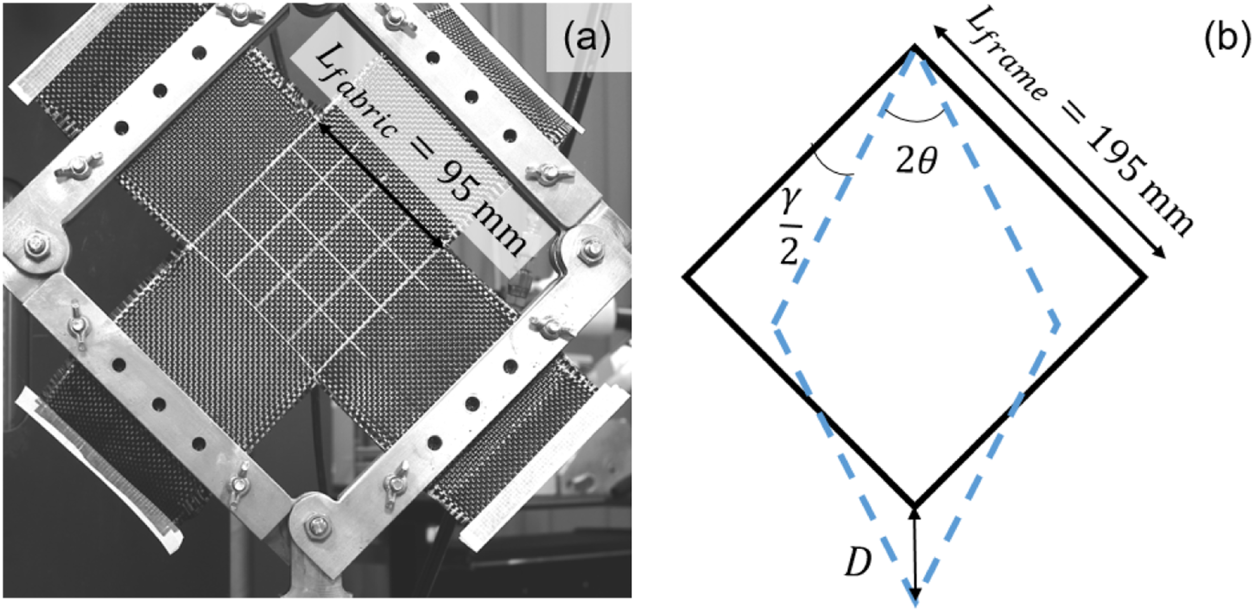
The in-plane shear behavior was characterized using a picture frame test, as shown in Figure 2. In the picture frame test, a piece of square fabric with removed corners was clamped by a set of metal frame bars with an edge length of 195 mm, as shown in Figure 2(a). The center region of the fabric, marked by the girds, is 95 mm × 95 mm. The frame was mounted on a hydraulically activated MTS load machine. The bottom crosshead first moved downwards at a rate of 35 mm/min for 96 mm. Then, it stayed still for three minutes and finally moved back at a rate of 35 mm/min to the initial position. Force, time and displacement were recorded during deformation. The shear angle, (a) Experimental setup of the picture frame test; (b) Illustration of the movement of the picture frame during the test. The black solid lines are the initial geometry of the frame, and the blue dash lines represent the rotated frame.


This calculation assumes that the work done per unit volume should be a constant if the same material is sheared by the same angle.
40
Consider two square fabrics with the same thickness 

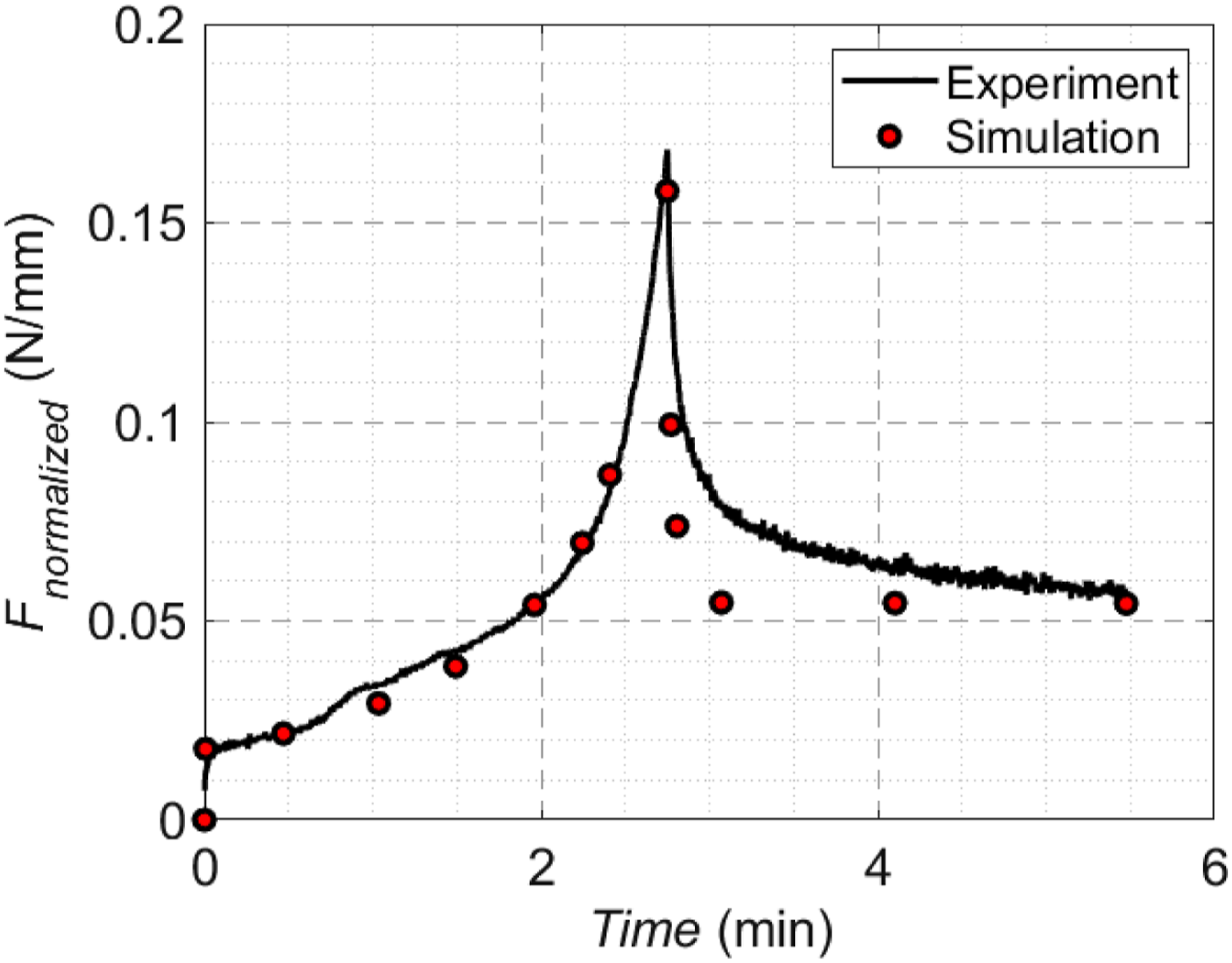
The normalized shear force versus shear angle obtained from the test is shown in Figure 3 together with the deformed shapes of the fabric at various deformation stages. Initially, the normalized shear force is very small, and there are large channels between fiber tows. As these channels gradually close, the force increases almost linearly with shear angle. Then, the shear force suddenly increases around the shear locking point due to compaction of neighboring fiber tows. If the fabric is subjected to further shear loading, the shear force will increase linearly again but with a larger shear rigidity, and wrinkles can be observed in the experiment.32,35,38 In this work, the shear angle increases up to 55°, which is around the locking angle of the fabric. The current study is focused only on the deformation of the fabric before the shear locking angle. The normalized shear force is also plotted against time in Figure 4 to show the viscous behavior of the fabric. Once the crosshead stops to move, the normalized shear force decreases rapidly from the peak within the first few seconds, followed by a steady decrease when the displacement is constant. The picture frame tests were repeated three times using different T-300 fabric samples, and consistent responses were observed. Figures 3 and 4 show the average testing results, which are subsequently used to characterize the fabric in-plane shear properties as discussed in In-plane shear model section. The shear force versus shear angle responses obtained from the experiment and simulation. The evolution of shear force obtained from the experiment and simulation.
The in-plane shear model
To correlate the in-plane shear behavior with fabric properties, an FEA model of the picture frame test was built in the commercial software Abaqus (version 2021), as shown in Figure 5. Fibers were created as wire parts meshed by 2-node linear beams in space (B31). The metal frames were modeled as isotropic beams with an elastic modulus of 200 GPa and circular cross-sections with diameters of 20 mm. It is found that changing the diameter of the frame bars does not affect the simulation results, if it is above 5 mm. The ends of the frame bars were pinned together, and the virtual fibers were pinned to the frame to represent the testing configuration. Relative rotation at each pin-joint was allowed. The bottom left corner of the frame was fixed, and top right corner was moved at 35 mm/min (the same as the speed in experiment) at 45° with respect to the x-axis for 2.62 min. The length of the frame, Illustration of the FEA model for the picture frame test including metal frames, virtual fiber tows, and boundary conditions.
To characterize the material and interaction properties, analyses were conducted with or without dashpots. At first, the dashpots were removed, and the material properties and spring stiffness were found by comparing the (a) The moment along the z-direction, 
Effects of the fiber properties in the in-plane picture frame test simulation
It is assumed that each fiber tow is fully incompressible, thus, The consistent normalized shear force obtained from the picture frame test simulation with various 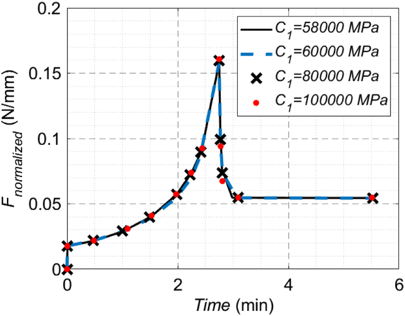
Bending behavior
The goal of the bending test is to characterize the geometry and material properties of the virtual fiber tow through cantilever beam tests. Four single-layer specimens of 3″ (76.2 mm) wide were prepared. The left end of each specimen was clamped between two metal blocks and the right part was suspended. The hanging lengths were 3″ (76.2 mm), 6″ (152.4 mm), and 9″ (228.6 mm), respectively, and each length of the specimen was tested four times. The bending tests for each fabric length were repeated four times using different T-300 fabric samples, and consistent responses were observed. The deflection of the fabric was recorded using a digital camera, as shown in Figure 8. To ensure the accuracy of the photographic measurement, the deflection of the fabric was also measured directly using a ruler. The average deflection of each fabric length is reported in Figure 9(b). The deformed fabric during tests in (a) 3″, (b) 6″, and (c) 9″ hanging lengths with 5 cm grids in the background. (a) Illustration of the FEA model for the bending test including virtual fiber tows and boundary conditions; (b) The consistent deflections from the experiments and simulations.

A corresponding bending simulation model was built in Abaqus as shown in Figure 9(a). The fabric in the model consists of virtual fibers which were modeled by Timoshenko beams. One end of the fabric was fixed. To characterize the bending properties, the weight of the model should equal to the weight of the real fabric 
Input model parameters for various tow spacing values.

Procedures to characterize the model inputs
Figure 10 shows a flowchart that summarize the procedure to determine the material and geometric properties used in the proposed discrete model. First, the properties that satisfy equation (8) were roughly estimated and used to predict the shear response of fabric during the picture frame test. Then, the length of the tow cross-section, Procedures to determine the input model parameters.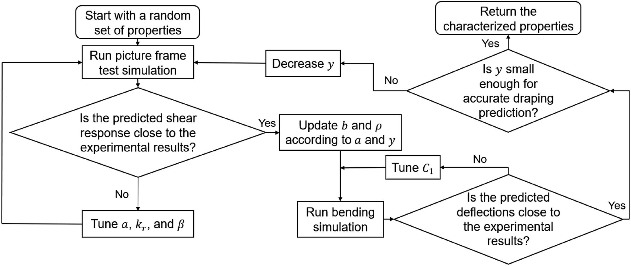
It is worth noting that the tow spacing is a user choice, while other fiber properties need to be adjusted to match the overall fabric response during material characterization. Whenever a new tow spacing is used, other properties should be characterized again. The tow spacing mostly influences the in-plane shear behavior, since the total shear force is related to the number of intersections. It also affects the predictive accuracy of the draping simulation. The predictive accuracy can be increased by decreasing the tow spacing, however, this will result in a more complex geometry and higher computational costs. Therefore, it is important to select a tow spacing that balances model accuracy and computational costs. In this study, three different tow spacings, ranging from 10 mm to 12 mm, were investigated, and the corresponding material properties are shown in Table 3 and Figure 11. (a) The 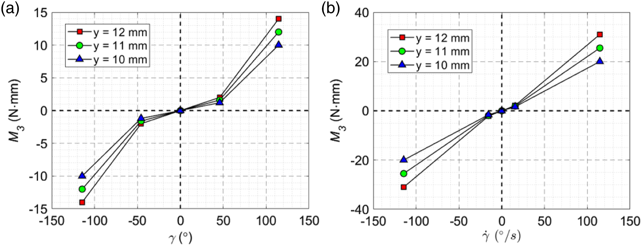
Validation
The focus of this section is to adopt the proposed modeling approach to predict the fabric draping behavior. To further validate the proposed the discrete model, a hemisphere draping study was carried out to demonstrate its capability to predict the deformed shape and the resulting shear angles.
Draping experiment
Figure 12 shows the hemisphere draping tool consisting of an acrylic blank holder, an aluminum die support, and a steel punch from top to bottom mounted on the MTS load frame. The outer diameter of the punch is 6″ (152.4 mm). A hole with a diameter of 160 mm was cut in the center of the die support and blank holder to enable the punch to deform the fabric. All the surfaces in contact with fabrics were polished and treated with aerosol oil lubricant to reduce friction. The draping tests were repeated three times using different fabric samples to understand the uncertainty associated with the testing. The setup of hemisphere draping test.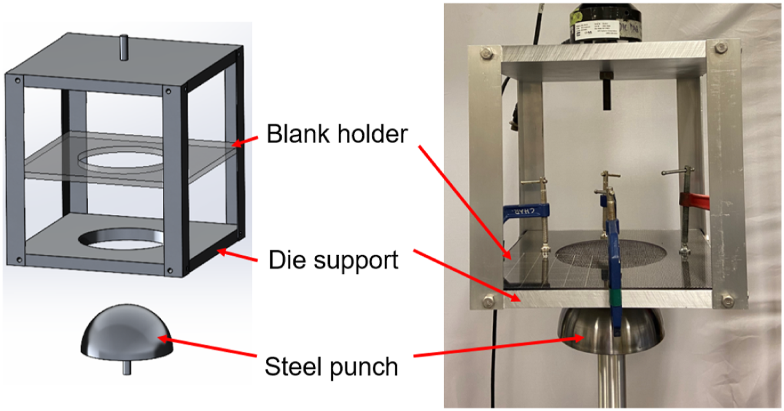
Prior to testing, gridlines were drawn on a layer of T-300 carbon fiber plain-weave ply. The ply was then placed on top of the die support and pressed by the blank holder. Initially, the punch was raised to touch the fabric. Then, the fabric was draped for 65 mm in 1 min. Photos were taken from the top view through the transparent blank holder to record the deformed shape and particularly the shear angle.
The deformed shape is shown in Figure 13. No obvious wrinkle was observed, while minor fiber sliding was evident on the hemisphere. The shear angles tended to be large along the diagonal lines ( (a) The draped fabric; (b) The five points where the angles between the warp and weft tows are measured. The setup of the hemisphere draping simulation consisting of a fixed die support, a moving punch, a moving blank holder, and a quarter of the fabric with symmetric boundary conditions (red dots). The angles between warp and weft tows from experiments expressed as averaged value and standard deviation (sample), together with the simulation results when different virtual tow spacings are used.


Draping simulation
The hemisphere draping response was simulated using the Abaqus dynamic implicit solver based on the material and geometrical properties characterized in Experimental characterization section. The setup was shown in Figure 14, including the blank holder, die support, and punch, which were modeled as rigid bodies with the movement controlled through the reference points. To improve the convergence with multiple contacts, the blank holder was pushed towards the fabric when the punch moved along the z-direction for 65 mm. Only a quarter of the fabric was included in the model, and symmetric boundary conditions were imposed at the bottom points (where
Figure 15 shows the deformed shape of the fabric subject to hemisphere draping. Generally, the predicted deformation of the fabric is in good agreement with the experimental measurement, since the blue triangles that represent the outline of the predicted deformed shape of the fabric capture the boundary of the fabric in the experiment, as shown in Figure 16(a). Similar to the experimental results, the shear angle first increased from the apex to the bottom of the dome and then decreased at the flat region as the position moved along the diagonal of the fabric layer. No out-of-plane wrinkle was observed. However, unexpected, small in-plane waviness occurred in the simulation. A possible reason is that, in the model, the virtual tows were not stretched by the fabric–tool friction exerted by the blank holder, which was not in contact with the fabric initially, allowing slight in-plane buckling. However, this buckling was prevented throughout the experiment due to the compression and friction at the surface of the blank holder. It is also possible that the unexpected in-plane waviness results from the error propagated from the characterization of properties, i.e., a slightly over-estimated rotational resistance and/or an under-estimated in-plane bending stiffness. The shear angles are also computed at the same five locations and summarized in Table 4, which are generally in good agreement with the experimental results. The largest error occurs at point 5, because the predicted shear angle is disturbed by the in-plane waviness. It can be concluded that the proposed model can accurately predict the shear angle and fabric deformation during the draping process. The discrete modeling approach clearly demonstrates the relationship between the fabric deformation modes, including shearing and bending, and the textile architecture. The combination of the fiber stiffness, geometry, and the interaction between the fibers determine the drapability of the textile fabric. The comparison of the deformed fabric from (a) the hemisphere draping experiment, and (b) the hemisphere draping simulation by using The comparison of the deformed fabric from (a) the hemisphere draping experiment, and (b) the hemisphere draping simulation by using 

To demonstrate that a tow spacing of 12 mm is not too large to generate inaccurate predictions, the draping simulation was also conducted with 11 mm and 10 mm tow spacing. The predicted fabric deformation is shown in Figures 16 and 17, respectively, and the shear angles at the five selected locations are summarized in Table 4. It has been found that a smaller tow spacing tends to better predict the fabric outline and shear angles. Generally, the three cases show similar predictions, indicating that the 12 mm tow spacing is sufficient in this study. The comparison of the deformed fabric from (a) the hemisphere draping experiment, and (b) the hemisphere draping simulation by using 
Discussion
In the hemisphere draping example, the primarily focus is on the flat zone due to the fact that the fiber tows undergo large shear deformation in the vicinity of the transition area of the punched and flat zones. Since a hemisphere mold is used, the fabric deformation in the punched zone is mainly determined by the punch geometry, while the deformation responses of the tows in the flat zone are significantly affected by the fabric properties. Moreover, the flat-zone deformation is the direct outcome of the deformation in the punched zone, and the determination of fiber orientation is more accurate when the measurement is taken on a flat surface than a curved surface. Therefore, the fabric deformation in the flat zone is selected for model validation. It should also be noted that it is critical to predict the fabric deformation in the flat zone. The change of shear angle affects the fabric permeability,1,3 which further affects the resin flow response in the subsequently composites manufacturing process.
Although the current study is focused on the T-300 carbon fiber plain weave fabric, it is expected that the proposed methodology can be applied for various types of fibers and weave patterns. Once the fabric is changed, the material properties need to be characterized following the procedures mentioned in Sec 3.5. A separate study on the effects of types of fibers and textile patterns is recommended for future research work. In addition, the current work is focused on the shear and bending responses of the fabric without considering the stretch or fracture of fibers. The proposed approach shows a significant computational advantage due to the adoption of virtual tows to account for the interactions between individual fibers in the yarn, however, the spacing between the virtual tows should be carefully selected to keep the prediction accurate and efficient while avoiding convergence issues. Currently, it requires a few iterations to determine the virtual tow properties based on the experimental results. However, this process can be automated in the future by using optimization methods. It should also be noted that the current model only accounts for a single layer of fabric. The through-thickness compaction and interaction of multiple layers of fabrics are considered in a separate study in. 41
Conclusion
In this paper, a new, efficient discrete fabric modeling approach is developed through the incorporation of virtual fiber tows modeled as Timoshenko beams and connected by the springs and dashpots at the intersections of the interlaced tows. The in-plane shear and out-of-plane bending properties were characterized by the picture frame and cantilever beam bending tests, respectively. The fabric relaxation behavior was successfully captured and characterized by adjusting the damping coefficients of the dashpots. The proposed method was implemented in commercial software Abaqus and applied to simulate the hemisphere draping process. The predicted deformed shape and shear angles of the fabric are in good agreement with the experimental results, demonstrating that the predictive capability of the proposed model when it is applied to simulate fabric draping processes. The proposed approach is innovative because it can capture the deformation of individual fiber tows while achieving computational efficiency in large-scale fabric draping simulations. The model is useful for understanding the effect of textile pattern on the resulting deformation response, and it can be employed to guide the design of fabric architecture to achieve target structural performance of the composite part manufactured via LCM.
Footnotes
Acknowledgements
The authors are grateful for the support of the National Science Foundation under Grant No. 2105448 and the Purdue University Libraries Open Access Publishing Fund. We also thank Mr. Yao Sun at Purdue University for his assistance in manufacturing the testing tools.
Declaration of conflicting interests
The author(s) declared no potential conflicts of interest with respect to the research, authorship, and/or publication of this article.
Funding
The authors received financial support from U.S. National Science Foundation to conduct this research. The publication cost of this article is supported through the Purdue University Libraries Open Access Publishing Fund.