
Abstract
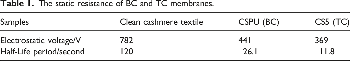
The effects of superimposed polymer membranes doped by graphene via the foaming micro-coating technique on the pilling and static resistance of coated cashmere fabrics are studied. The bonding behaviors to fibers of polymer, which are inescapable in the traditional dipping processing technique, are avoided by the foaming micro-coating technique. Some flexible hydrophilic cationic polyurethanes are purposefully designed and employed in the micro-coating processing of cashmere fabric, and the effects of different coating techniques on the pilling, static, UV and washing resistance of coated cashmere fabric are studied. Results show that the semi-embedded graphene in the “top coating” membrane contributes to static resistance. The pilling resistance of cashmere fabric covered by polymer membranes is enhanced from Grade 1.5 to Grade 4.5 when the its weight gain rate of “bottom coating” reaches 1.5% (o.m.f.), and its static voltage half-life decreases from over 120 s to about 1 s because of functional “top coating.” In addition, the ultraviolet protection factor value of the finished cashmere is doubled, and its anti-pilling and anti-static effects can tolerate more than five times of washing.
Introduction
The pilling and static accumulation of cashmere textiles are always the focus of consumers’ criticism, and they greatly restrict the development of cashmere products.1–3 In the past 10 years, the “subtraction processing” technique based on the peeling of the scales of cashmere fiber has faced the possibility of elimination due to its complex procedure, unacceptable fiber damage, and poor environmental protection.4–6 Meanwhile, the “addition processing” technique based on polymer coating usually results in serious deterioration of the natural style of cashmere fiber.7–9
Relevant research has shown that effectively controlling the distribution of polymer on fabric is difficult for the conventional “dipping processing” or “coating processing” technique that inevitably resulting in the deterioration of the excellent natural style of textiles.10–12 Both techniques inevitably fix the fabric structures and the positional relationship of yarns and fibers due to the bonding effect of polymer. Therefore, soft, fluffy, flexible cashmere fiber requires a new technique of using polymer in cashmere coating.13,14
In the past decades, various technologies have been utilized in related fields. One of the difficulties in the surface chemical treatment of cashmere fiber is derived from its dense and hydrophobic scale structure, which easily causes pilling and electrostatic accumulation but also prevents various chemicals from adhering to the surface.15,16 To endow wool fabrics with anti-pilling and anti-felting properties, Chang et al. prepared silica nanocapsules through silica shells and hyperbranched polyethoxysiloxane (PEOS-m PEG) with a self-assembly method. The mechanical properties of the nanocomposite anti-felting agent films were improved in comparison with the neat polymer, and correspondingly the pilling-resistance of textiles was improved. 17
In addition, on the basis of the controllable “addition processing” treatment, functional materials have been properly treated on the fiber surface to give full play to their antistatic and antibacterial functions. The graphene, which has the unique electrical, mechanical and thermal properties, is currently under research phase for its functional applications in the field of textiles.18,19 For example, Cao et al. used graphene to finish textiles and the form continuous functional films on their surfaces gave the textiles good antibacterial, antistatic, UV, and photocatalytic self-cleaning properties.
20
Zhao and coworker prepared highly dispersion sulfonated graphene for fabric antistatic finishing, and the finished fabrics showed good antistatic performance after being washed 20 times.
21
As well as, Zeng et al. coated a novel trap structure containing graphene oxide and polyaniline arrays on the surface of cotton fabrics, exhibits significant antistatic property, while can remarkably inhibit the growth of E. coli and S. aureus.
22
Schematic diagram of superimposed micro-coating on the surface of cashmere fiber.
Evidently, the continuous distribution of film-forming polymers on the surface of cashmere fiber must be effectively controlled and made as thin as possible to ensure that graphene existing in the polymer membrane is partially exposed, which is a requirement for the function, hand-feel, and durability of antipilling and antistatic cashmere textile.23,24 Therefore, this study designed superimposed polymer membranes on the surface of cashmere fiber through “bottom coating” (BC) plus “top coating” (TC) with cationic waterborne polyurethane (Figure 1). The effects of different micro-coating techniques on the pilling resistance, static resistance, anti-UV resistance, and washing properties of the coated cashmere textile were studied.
Materials and methods
Materials
Cashmere textile (178 g/cm2) were supplied by Hebei Doveikang Auxiliaries Co., Ltd, Anionic waterborne polyurethane CSPU and CS5 (25 wt.%) was purchased from Guyin New Material Technology Co., Ltd, Shanghai, China. Graphite and CNC was provided by XFNANO, Nanjing, China. Lauryl betaine, Cationic modified guar gum, Acetic acid, Hydrochloric acid, Sodium hydroxide were obtained from Sinopharm Chemical Reagents Co., Ltd.
Preparation of CNC-graphene dispersions
Cellulose nanocrystal (CNC)–graphite powder mixtures with different concentration ratios (1:2, 1:1, and 2:1) were delaminated in an ultrasonic processor (UP400S) by using the probe of the cell pulverizer with a pulse time of 0.5 s, amplitude of 70%, and ice water bath conditions. Three types of graphene with concentration ratios of 1/2, 1/1, and 2/1 were prepared by adding 50, 100, and 200 mg of CNC and 100 mg of graphite powder to 100 mL of deionized water for full delamination.
Surface modification of cashmere knitted textile
Foam micro-coating: Clean cashmere fabric was dried in a vacuum drying oven at 70°C to a constant weight (m1). The functional foam was placed on the dried cashmere fabric by the foam dyeing and finishing machine F100 (Neowin Chemicals Co., Ltd, Shanghai) at a speed of 8 m/min, then the cashmere fabric is prebaked with infrared heater and subsequently baked in the oven at 90–100°C for 5 min to a constant weight (m2). The foam micro-coating process of the cashmere knitted textile is shown in Figure 2. Foam micro-coating unit for BC and TC.
Foaming liquid formula: CSPU or CS5 (60 g/L), lauryl betaine (7 g/L), and cationic modified guar gum (7 g/L) were employed. The weight gain rate (WGR) of the fabric coated with polymer membrane was controlled at about 1.5% (o.m.f.).
Addition process: The clean and dried cashmere fabric (m1) was dipped in CSPU or CS5 polymer emulsion at room temperature for 20 min then dried at 90°C (m2). The WGR of the fabric coated with polymer membrane was controlled at about 1.5% (o.m.f.). Equation (1) is used to calculate the WGR.

Performance and structural characterization
FTIR
FTIR was measured using a Nicolet iS5 infrared spectrometer (Thermo Scientific, USA) by potassium bromide tablet method at 25°C and the test range is 400–4000 cm−1.
SEM
A S-4800 scanning electron microscope (JEOL, Japan) is employed in surface morphology analysis. The cashmere fibers treated by different finishing technique are gilded and observed.
TEM
A Joel-2100F transmission electron microscope (JEOL, Japan) is employed in fabric surface morphology analysis with an accelerating voltage of 10 kV.
TG
A TG-209 (NETZSCH Scientific Instruments Trading Ltd., China) thermogravimetric analyzer is employed in thermal performance analysis. The heating range is 100–900°C and the heating rate is 10°C/min.
Emulsion particle size
A ZS90 nanoparticle size analyzer and a zeta potentiometer (Malvern, UK) were employed for the analysis of the emulsion particle size and its distribution. The sample was diluted to 1 wt.% and subjected to ultrasound for 30 min at 25°C.
Pilling resistance
A GT-7012-M (Goodtechwill Testing Machines Co., Ltd, China) martindale abrasion tester was employed in the pilling resistance analysis. The pilling resistance of the treated cashmere fabrics was evaluated in accordance with the standard method (ASTM D4970/D4970M-2016ε3) at 20°C and 65% relative humidity (RH).
Static resistance
An FY342E-II (Fangyuan Instrument, China) fabric inductive electrometer was employed in the static resistance analysis. The clean cashmere textile was treated with the polymer emulsion at a bath ratio of 1:20 and 1.5%WGR (o.m.f.) in accordance with ISO:18080-1:2015 (“Test methods for evaluating the electrostatic propensity of fabrics — Part 1: Test method using corona charging”); temperature of 20°C and RH of 40%.
Comprehensive hand-feeling
The treated cashmere fabric was moistened for 24 h at 20°C and 65% RH. The softness, elasticity, fluffiness, and drape styles of the cashmere fabric were evaluated through the subjective touch evaluation method.
UV resistance
An M284 UV transmittance and sunlight protection test system (Dongguan Zhenglan Precision Instrument CO., LTD, China) was employed in the UV resistance analysis. In accordance with AATCC TM183:2020 (“Test Method for Transmittance or Blocking of Erythemally Weighted Ultraviolet Radiation through Fabrics”); the temperature was set to 21°C, and RH was set to 65%.
Washing resistance
The accompanying washing fabric was selected to be polyester in accordance with ISO 6330:2021 (“Textiles — Domestic washing and drying procedures for textile testing”).
Results and discussion
Structure and properties of cationic polyurethanes for BC and TC
In accordance with the function design of BC and TC polyurethanes
The medium-strength absorption peak at 3440 cm−1 shown in Figure 3 was attributed to the stretching vibration of N-H in the carbamate groups, and the absorption peaks at 2918, 2925, and 1150–1465 cm−1 were caused by the stretching and bending vibrations of C-H groups in the polymers. The absorption peaks near 1677 and 1577 cm−1 and near 1595 and 1705 cm−1 were attributed to the stretching vibration of C = O and bending vibration of N-H in the carbamate groups, respectively. The absorption peaks at 1112 and 1120 cm−1 were attributed to the stretching vibration of C-O-C and Si-O-Si in the polyether and polysiloxane chain segments, respectively. Infrared spectrum of BC and TC polyurethanes.
According to Figure 4, the average particle size of the cationic BC polyurethane emulsion was 75.8 nm, and its particle size distribution was unimodal. Meanwhile, the average particle size of the cationic TC polyurethane emulsion was 127.5 nm, and its particle size distribution was bimodal. In reality, the average particle sizes of the two polyurethane emulsions are small because the molecular weights of the two polymers are small enough because their tails are actively caped by the amino silane coupling agent. The hydrophilicity of polyether chains in their molecular structures is also conducive to the formation of a stable emulsion.25,26 Particle size analysis of BC and TC polyurethane emulsion.
With regard to the particle size distribution of the emulsions, the chemical structure of TC polyurethane was linear, and hydrophilic polyether and hydrophobic polysiloxane were simultaneously distributed on it. An amphipathic linear macromolecule usually has strong water absorption, resulting in high emulsion viscosity at the beginning of the emulsification process. 27 This is why the particle size distribution of TC polyurethane exhibits a bimodal distribution although its hydrophilicity is better than that of BC polyurethane. Hence, the difference in the molecular structures of BC and TC polyurethanes is also reflected in their particle size and distribution.
The static resistance of BC and TC membranes.
Structure of graphene and properties of its dispersion liquid
Ultrasonic stripping processing was applied to prepare a group of graphene samples with an intact structure and excellent electrical conductivity under different ratios of CNC to graphite powder.
As indicated in Figure 5, the stretching vibration peak of -OH (3428 cm−1) in the pure graphite powder was caused by the fact that the purchased graphite powder contained a small amount of oxygen-containing groups. The absorption peak around 3428 cm−1 was the stretching vibration peak of -OH in CNC. The absorption peaks at 2943 and 1050 cm−1 were the stretching vibrations of -CH2 and C-O, respectively. The absorption peaks at 1388 and 1190 cm−1 were ascribed to the stretching vibration peaks of S = O because of the remaining sulfonic groups in CNC prepared via the sulfuric acid hydrolysis technique. The absorption peak of 1632 cm−1 was attributed to the stretching vibration of C = C. FTIR spectrum of CNC-graphene.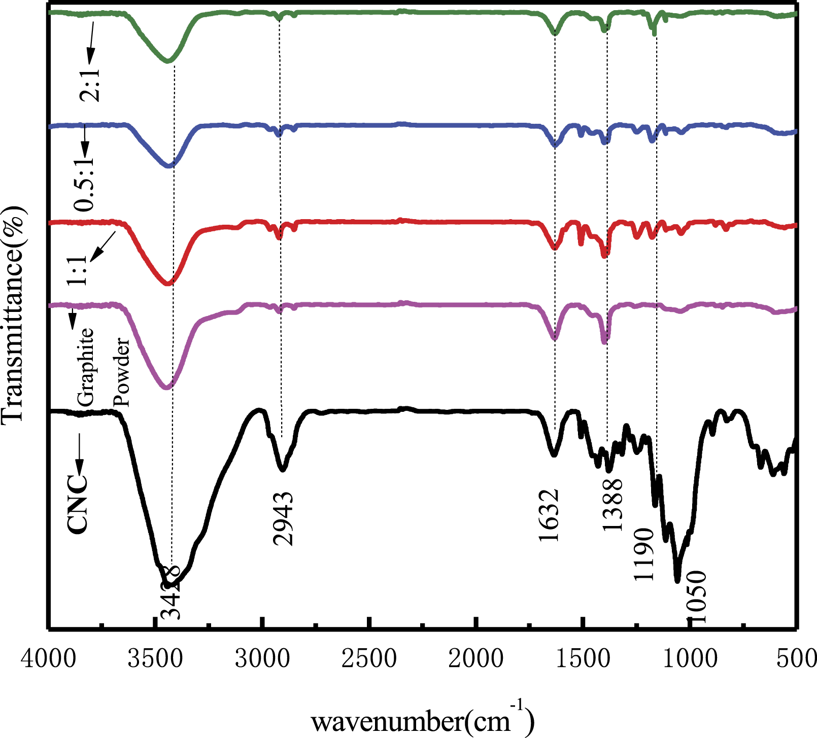
According to Figure 6, the crystallinity of the graphite powder was very strong, and it had a distinctly stronger diffraction peak at 2θ = 26.8°.
28
When graphene was prepared by ultrasonic stripping, the intensity of the crystallization diffraction peak of graphite powder decreased gradually as the CNC: graphite powder ratio increased, that is, the higher the proportion of CNC was, the higher the efficiency of the peeled graphite powder was, indicating reduced crystallinity. X-ray diffraction spectrum of CNC-graphene.
According to the analysis above, the position of the specific infrared absorption characteristic peak of the graphene stripped and dispersed by CNC did not shift, and its crystallinity decreased significantly under the action of high-frequency ultrasound, indicating that the graphene prepared by the physical stripping method was not only fully stripped, but also basically free of oxidative damage. 29
The larger the amount of employed CNC was, the larger the mass loss of the sample was; the mass loss rate (MLR) of CNC was about 80.7% when the temperature reached 800°C (Figure 7). However, the graphite powder had almost no mass loss even when the temperature approached 800°C. Moreover, the MLRs of the samples wherein the “CNC:graphene ratio” was 1:2, 1:1, and 2:1 were 18.7%, 30.1%, and 63.2%, respectively. The MLRs of the samples were constantly increased by the increase in CNC proportion in the samples because the content of the organic structure in these samples also increased. Owing to the high content of graphene in Samples 1:2 and 1:1, the residual mass did not change. TG spectrogram of CNC-graphene.
Notably, according to our calculation, the WLRs of CNC–graphene at 1:2, 1:1, and 2:1 should be 26.7%, 40.4%, and 53.4%, respectively, if the contribution of CNC’s weightlessness is subtracted from the total weightlessness of the CNC–graphene samples. The graphene prepared in this study was mixed with a certain amount of CNC. The higher the proportion of graphite powder was in CNC–graphite, the less CNC was “wrapped” in CNC–graphene. In particular, the MLR of CNC–graphene was 63.2%, which is higher than the theoretical value of 53.4%, when the ratio of CNC to graphite powder was increased to 2:1, which indicates that an excessive amount of CNC may lead to oxidation damage on graphene. The result also suggests that although a small amount of CNC is beneficial to the preparation of lossless graphene, it is not conducive to the effective peeling of graphite powder.
The zeta potential of graphene dispersion and its mixture with TC polyurethane emulsion can reflect its chemical structure and application performance to a certain extent. Figure 8 shows that the electrokinetic potential of the self-made graphene dispersion was almost zero within pH 5–8, indicating that the graphene prepared at the CNC–graphite powder ratio of 1:1 had almost no oxidation damage, which benefited its electrical conductivity.
30
The electrokinetic potential of the TC foaming solution (CS5 60 g/L, sodium dodecyl sulfate 7 g/L, sodium alginate 7 g/L, and graphene dispersion 0 or 0.56 g/L) was a weak positive and showed almost same regardless of whether graphene was dispersed in the TC foaming solution or not. This result demonstrates that the self-made graphene had a complete ring structure which will surely do not affects the electrical properties of TC polymer emulsion.
31
Effect of pH on Zeta potential of cationic foaming solution.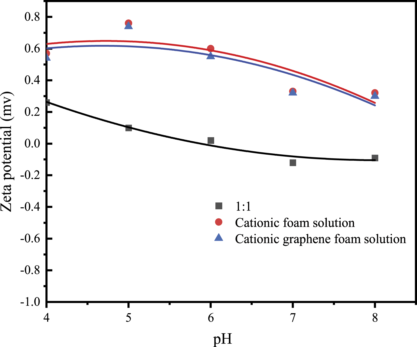
Micro-Coating finishing of cashmere fabric based on BC and TC polyurethanes
Construction of superimposed coating and pilling resistance of cashmere fabric
The pilling resistance of cashmere fabric treated with different BC, TC and their organization.

Note: UC means clean untreated cashmere fabric.
In Table 2, “COF” means foaming BC (CSPU 60 g/L, laurate betaine 7 g/L, and cationic modified guar gum 7 g/L), “CSF” means foaming TC (CS5 60 g/L, laurate betaine 7 g/L, and cationic modified guar gum 7 g/L), “CHF” means foaming BC subjoining foaming TC (CS5 0 g/L, graphene dispersion 0.6 g/L, laurate betaine 7 g/L, and cationic modified guar gum 7 g/L), “CFF” means foaming BC subjoining foaming TC (CS5 60 g/L, graphene dispersion 0.6 g/L, laurate betaine 7 g/L, and cationic modified guar gum 7 g/L) and “CFD” means foaming BC subjoining Conventional dipping TC (CS5 60 g/L, graphene dispersion 0.6 g/L) (Figure 9). Different micro-coating combinations.
According to the pilling resistance of the treated cashmere fabric shown in Table 2, compared with the UC and COF columns, BC processing had great importance to the pilling resistance of cashmere fabric. The pilling resistance of the BC-processed cashmere fabrics was improved from Grade 1.5 to about Grade 3 and showed a certain washing resistance. However, the comparisons of UC and CSF columns and CHF and CFF columns revealed that TC had a positive effect on the pilling resistance of cashmere fabrics, but its effect was weaker than that of BC because the TC polyurethane was designed to be linear with strong hydrophilicity. Based on the above research results, the BC resin with stronger film-forming property can cover the cashmere fiber scales more effectively than the TC resin, and endowing the treated fabric with significantly better anti-pilling performance.
The comparison of CFF and CFD columns showed that CFD was highly beneficial to the full coverage of fiber scales by the polymer, but it could not avoid the “bonding” effect of the polymer on the fiber and yarn, resulting in the poor hand-feel of the cashmere fabrics.
Therefore, for the anti-pilling finishing of cashmere fabrics, “foaming BC subjoining foaming TC” was deemed to be the best technical scheme choice. The pilling resistance of the treated cashmere fabric could be improved from Grade 1.5 to Grade 4.5, and the washing resistance could be enhanced.
Construction of superimposed coating and static resistance of cashmere fabric
The static resistance of cashmere fabric treated with different BC, TC and their organization.

Note: UC means clean untreated cashmere fabric.
In particular, the comparison of CFF and CFD columns revealed that dipping TC processing could not avoid the cementation among the fibers and yarns that the TC polyurethane caused, resulting in a poor hand-feel and an ambiguous contribution to the antistatic performance of cashmere fabric. According to the CFD column, the static resistance of the cashmere was reduced, but its static resistance was still better than that in the CFF column after the samples were washed several times. This result is due to the fact that the graphene in CFD processing was completely covered by TC polyurethane because graphene was directly dispersed in the emulsion of TC polyurethane, and washing helped expose the TC-covered graphene.
In conclusion, “Foaming BC + Foaming TC @ half-wrapped graphene” was the best technical solution for the anti-pilling and antistatic composite finishing of cashmere textiles. The half-life of the treated cashmere fabric was reduced from over 120 s to 1.0–68.3 s, and the fabric exhibited improved washability.
Construction of superimposed coating and thermal and UV resistance of cashmere fabric
The above-mentioned about the findings on the relationship between the pilling and static resistance of the treated cashmere fabric, and how to organize the superimposed coating can be confirmed by UV resistance (Figure 10). The UV resistance of the cashmere textiles with the superimposed coating was greatly improved, which indicated that the polysiloxane-modified polyether cationic waterborne polyurethane and graphene had high UV resistance.32,33 UV resistance of superimposed coated cashmere fabric.
As that indicated in Figure 11, the mass loss of the samples treated with different BC and TC processing before 100°C was attributed to the volatilization of their regained moisture. The weight loss in the range of 200°C–400°C was mainly caused by the thermal decomposition of CNC and polyurethane coating. The weight loss in the range of 260°C–350°C was mainly caused by the thermal decomposition of carbamate and CNC, and that in the range of 350°C–450°C was caused by the thermal decomposition of polyether polyols in the polyurethanes. In the range of 450°C–800°C, only the untreated cashmere had a mass loss due to its high content of organic structure; the residual mass of the cashmere coated by graphene had no significant change due to the excellent thermostability and thermal conductivity of graphene distributed on the surface of the cashmere fiber. Thermal resistance of superimposed coated cashmere fabric.
Morphology of BC membrane on cashmere fiber surface
The morphologies of the BC membrane on the surface of the cashmere fiber treated by the different processing schemes clearly support the relevant analysis and findings mentioned in this paper (Figure 12). As expected, compared with “Dipping process,” the cashmere fiber’s scales were not only fully covered after foaming processing, but their structure was also clear and intact, which indicated that the BC and TC menbrane endowed by “Foaming process” is superfine. SEM of cashmere fiber surface after different BC processing.
Figure 13 clearly shows the full wrapping effect of the CFD process on graphene, and the CFF process had a clear semi-wrapping effect on graphene. This observation further proves that the technical solution of “Foaming BC + Foaming TC @ half-wrapped graphene” for the anti-pilling and anti-static finishing of cashmere fabrics is reasonable and feasible. TEM of cashmere fiber surface after different TC processing.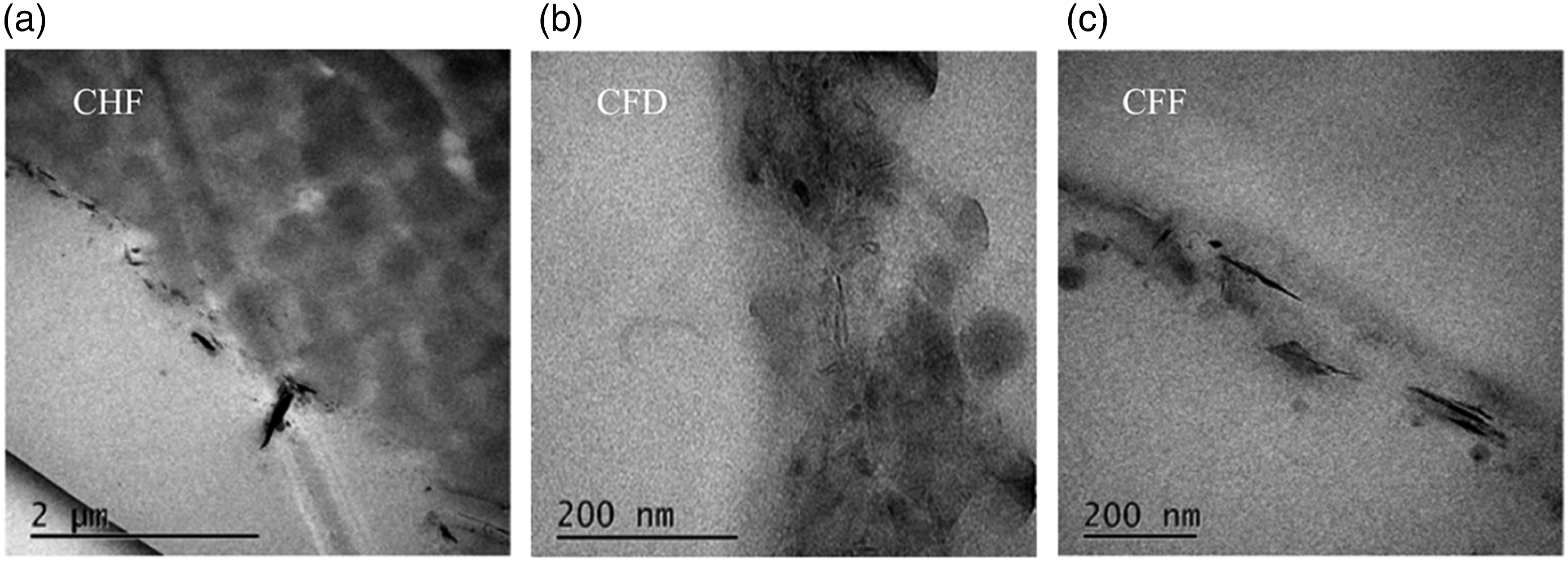
Conclusions
Graphene was prepared using the ultrasonic peeling technique. The higher the ratio of cellulose nanocrystals (CNC) to graphite powder was, the larger the amount of peeled graphite powder was. When the ratio of CNC to graphite powder was 1:1, graphene was fully exfoliated, and almost no oxidation damage occurred.
The graphene prepared through the ultrasonic stripping technique had a certain amount of wrapped CNC, and the larger the proportion of graphene powder in “CNC–graphite powder” was, the less CNC was wrapped in the obtained graphene. Excessive CNC in “CNC–graphite powder” could result in oxidation damages to graphene. A small amount of CNC is beneficial to obtaining pure and lossless graphene, but it is not conducive to the effective peeling of graphite powder.
The bottom coating (BC) and top coating (TC) were found to be crucial to the improvement of the pilling and static resistance of the cashmere fabric, respectively. “Foaming BC + Foaming TC @ half-wrapped graphene” is determined to be the best technical solution for the anti-pilling and antistatic composite finishing of cashmere textiles. The anti-pilling grade of cashmere fabric can be improved from Grade 1.5 to at least Grade 4, and the static voltage half-life can be reduced from over 120 s to 1–20 s, accompanied with improved washing resistance.
Cashmere fabrics treated with “Foaming BC + Foaming TC @ half-wrapped graphene” can demonstrate excellent UV resistance. Moreover, the scales of the cashmere fiber are completely covered by foaming coating, and the gaps of the fibers/yarns are not sticky. Consequently, the natural style of cashmere can be effectively protected.
Footnotes
Declaration of Conflicting Interests
The author(s) declared no potential conflicts of interest with respect to the research, authorship,and/or publication of this article.
Funding
The author(s) disclosed receipt of the following financial support for the research, authorship, and/or publication of this article: Key R&D program of Hubei Provincial Science and Technology Department (Project No: 2021BAA209), Hebei Province high-tech generic key technology research and application demonstration project (Project No: 18211407D), open fund project of Hubei Province Key Lab of Biomass-fibers and Eco-dyeing & Finishing (Project No: STRZ202112).