
Abstract
Aerodynamic characteristics of a cylinder covered with smooth fabrics and grooved fabrics were studied with wind tunnel test and numerical simulation, emphasizing on drag attenuation. In the wind tunnel test, the aerodynamic drag of nude cylinder and cylinder covered with fabric was measured. The results show that the drag coefficient of the smooth fabric is almost the same as that of the nude cylinder, however, the fabric with micro-groove structure exerts a distinct characteristic on drag reduction behavior. Based on the results of wind tunnel test, the smooth part of fabric with groove is simplified to smooth surface for numerical simulation. The simulation results of the pressure, vorticity, and turbulent kinetic energy on the grooved surface are presented in comparison with those of the smooth surface to illustrate the drag reduction mechanism. The results indicate that for the grooved surface, the pressure difference between the front and back of the cylinder is smaller, the vortex shedding is inhibited more effectively, and the turbulent kinetic energy is higher compared to those on the smooth surface.
Keywords
Introduction
Minimizing drag is essential in sports that aim to complete the required distance in the shortest possible time. In high-standard competitions, the differences in athletes’ performance are remarkably small. Thus, it is necessary to optimize the posture1,2 and equipment3,4 during the race to reduce drag and obtain a competitive advantage. As an indispensable piece of equipment in most sports, the drag-reducing effects of clothing has been proven in many sports.5,6 Therefore, understanding the aerodynamic characteristic of fabrics is of great help to improve the athletes’ performance.
Form prior studies, despite the complex structure of the human body, the body parts can be represented as multiple cylinders for aerodynamic evaluation. So, the circular cylinder is employed as a basic model to understand the aerodynamic characteristic. A fundamental idea to reduce the drag of a cylinder is to induce turbulence in the boundary layer, thereby delaying the flow separation from the cylinder, causing a narrower wake. This would trigger the drag crisis which is favored in sports, as the drag can be significantly reduced.
Previous studies show that the flow around bodies can be manipulated by the surface structure. A typical way is to introduce tiny surface structures as a surface pattern for altering the original boundary layer and wake flow structure. For example, the use of grooves, 7 dimples, 8 and low-profile vortex generators 9 can increase the momentum of the flow and change the fluid force against the cylinder profoundly. It has become quite common to see grooves on some athletic garments. 10 In this study, we focus on the aerodynamics of the cylinder covered with fabrics with grooves.
There are mainly two different approaches usually are used to assess the aerodynamic characteristics: (a) Experimental techniques either with wind tunnel experiments; (b) Computational fluid dynamics (CFD). The wind tunnel provides a simulation that approximates the flow over an experimental model within a controlled environment. The accuracy of such a simulation depends upon the extent to which the environment is replicated in the wind tunnel, the geometric accuracy of the model, and the wind speed matched to competition conditions in terms of Reynolds number. 11 In wind tunnel testing, the speed and direction of the flow can be held constant. Hence, the measurements made in a wind tunnel are generally very repeatable. Researchers have previously used a simplified cylindrical geometry to evaluate the aerodynamic properties of textile features such as tightness, 12 surface morphology13,14 and so on. CFD has been extensively used to study the aerodynamic characteristics of cylinders with different surface. With the development of computational fluid dynamics, there are more and more studies using this technology to analyze the fluid flow characteristics in related engineering applications.15–18 CFD can be useful for flow visualization and understanding general flow phenomenon. 19 These two methods have their own advantages in aerodynamic research, so it is very meaningful to combine the two methods to study the aerodynamic properties of fabrics.
In this work, we investigated the effect of the fabric with groove structure upon drag reduction of the cylinder. We conducted detailed measurements on a circular cylinder wrapped with fabric in a wind tunnel. Furthermore, the flow characteristics of smooth cylinder and cylinder covering by fabric with grooves are calculated by numerical simulation, including drag coefficient, pressure distribution, vorticity distribution, and turbulent kinetic energy distribution, so as to visualize the influence of grooved structure on the flow characteristics around the cylinder.
Experiment
Wind tunnel facility and test model
The measurements were conducted in Beijing Jiaotong University, China, at 25 ± 2°C and 65 ± 5% RH. The high-speed test section (3 m wide, 2 m high, and 15 m long) was used for this experiment. A circular cylinder was used as the test model, because the aerodynamic characteristic of the cylinder model is similar to that of the human body. It has a diameter of D = 0.0924 m and a height of H = 0.51 m. Four layers and 12 mesh damping nets were installed at the front of the inlet so that the inhomogeneity of the velocity field is less than 1%. In the present study,
Two multi-axis force-torque balances were used for the force measurement. The drag coefficient per unit span of a cylinder,

Then, drag impact,

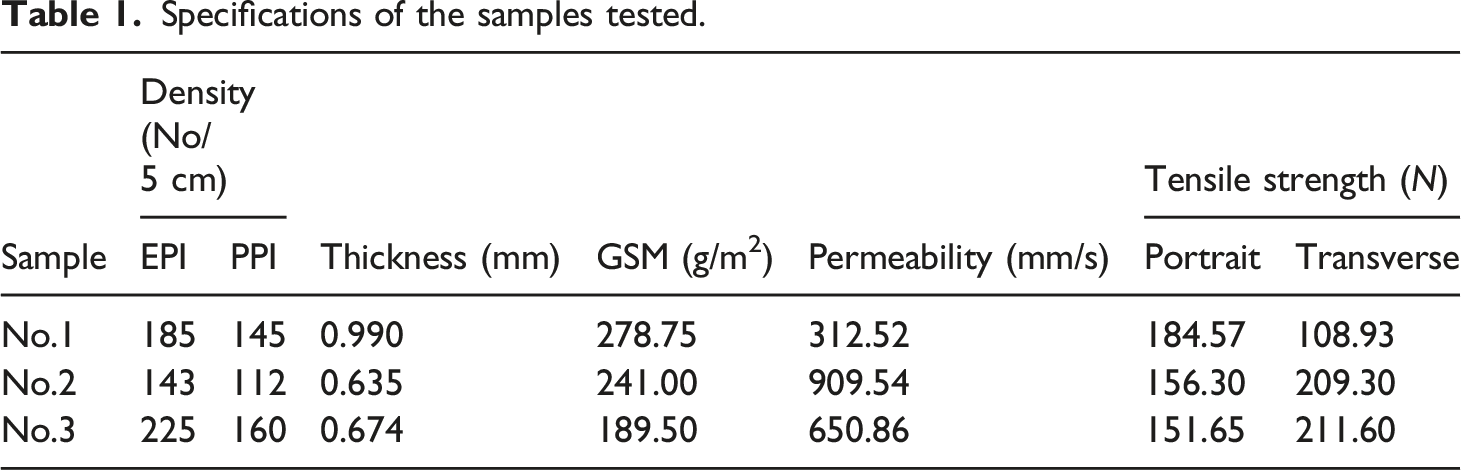
Surface pattern
Specifications of the samples tested.
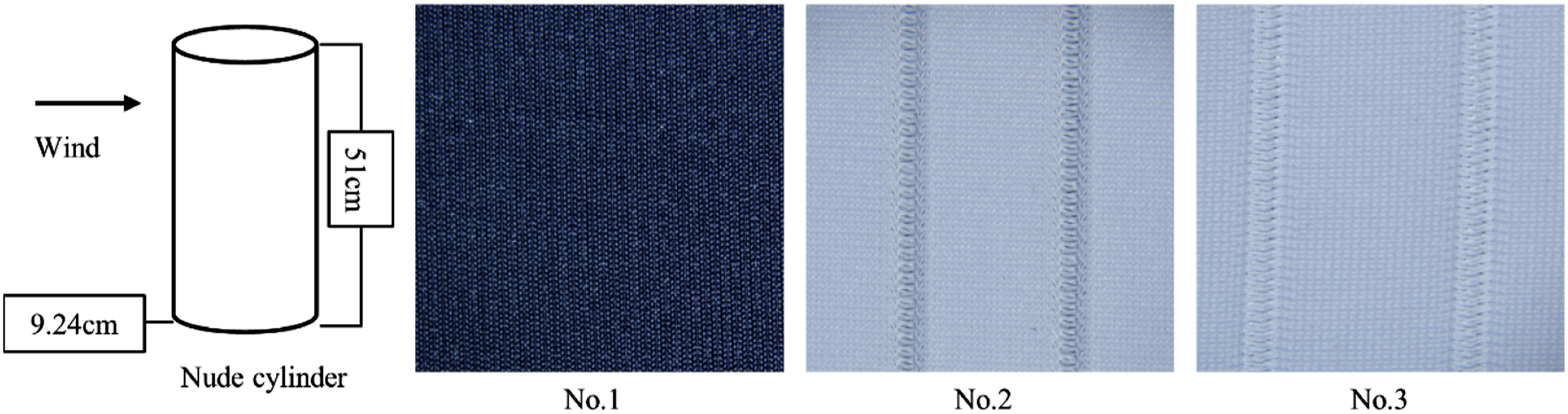
Samples used in the wind tunnel experiment.
Numerical model
The k-ω SST model
The RANS equations can be expressed as follows

Due to the inclusion of the Reynolds stress representing the effect of turbulence, a turbulence energy model should be introduced to close equation (4). The representative models are k-ε model and k-ω model. The k-ε model can better simulate the fully developed turbulent flow far from the wall, while the k-ω model is more widely used for boundary layer problems under various pressure gradients. 20 The SST k-ω model, which combines the advantages of the two models, retains the k-ε model near the wall and applies the k-ω model far away from the wall. These characteristics are very important for the accurate simulation of the boundary layer separation process, which is essential for obtaining good results of the bluff body flow.21–23 The shear stress transport (SST) k-ω turbulence was chosen to calculate the flow around the structure.
Calculation domain and boundary conditions
The computation domain and boundary conditions in the simulation process are depicted in Figure 2. The distance from the center of the circle to the flow inlet was 5D, whereas the distance to the outlet was 15D. The distance from the circular cylinder to the wall boundary surface on both sides was 5D. Schematic of the computational domain.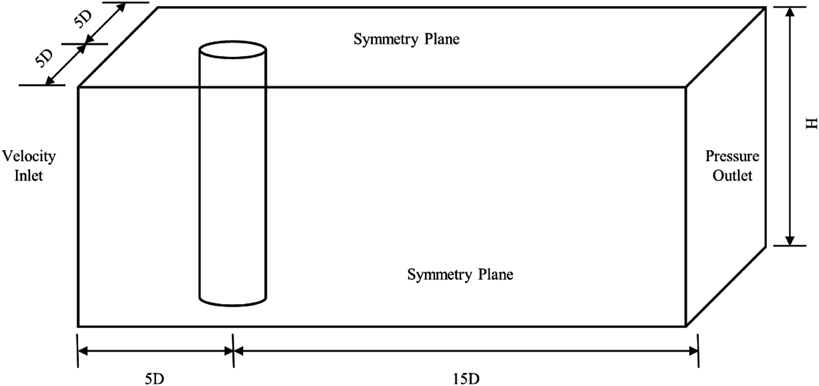
A uniform incoming fluid velocity was imposed on the inlet of computation domain. The pressure boundary condition was set at the outlet which ensures development of the flow field at the back of the computation domain. Symmetric boundary conditions were set on other boundaries of computation domain. No-slip wall boundary condition was imposed on the surface of the cylinder.
Results and discussion
Wind tunnel experiment results
A comparison of measured Variation of drag coefficient with Reynolds number. Variation of drag reduction rates with Reynolds number.

The cylinder covered with smooth fabrics is equivalent to introducing the homogeneous surface, while the grooved fabrics consist of grooves and the homogeneous surface. As shown in Figure 3, the homogeneous surface has little influence on the fabric, so it is reasonable to assume that the drag reduction effect of the fabrics with grooves is due to the groove structure. Based on this hypothesis, the homogeneous surface is simplified to a smooth surface when using a computational fluid dynamics (CFD) method to study the drag reduction properties, so as to focus on the effect of grooves on the drag coefficient.
Simplification of fabric surface
Because the drag of smooth fabric is similar to the nude cylinder, the smooth part of the fabrics with grooves is simplified as smooth surface. To obtain the geometry of the grooves, the texture images are observed using the super deep scene 3D microscope (DVM6), and the 3D models are generated by Wolfram Mathematica 8.0/9.0®. As shown in Figure 5, No.2 and No.3 have, similar distributed grooves but different parameters of the grooves. Figure 5(a) shows grooves geometries. As shown in Figure 5(b), the surface geometries are modeled to correspond to the geometries of fabrics with grooves. 3D and simplified models of fabric surface.
Establishment of grid models
The quality of grid determines the accuracy of simulation, so the generation method of grid is very important for numerical simulation.24–26
Grid in the computation domain
The computational grid has been generated by the ICEM software. For avoiding the effects of the wall, extremely fine grids are used in the boundary layer in the boundary layer close to the walls. For decreasing the calculation costs, the coarser grids are used in the far regions. This meshing method can balance the simulation accuracy and computational efficiency.
27
Because the SST k-ω turbulence model is adopted, the mesh resolution of the riser-wall is used with y+, which is about 1.28,29 The global view of the computational domain and a close-up around the cylinder are shown in Figure 6. Mesh in the computational domain.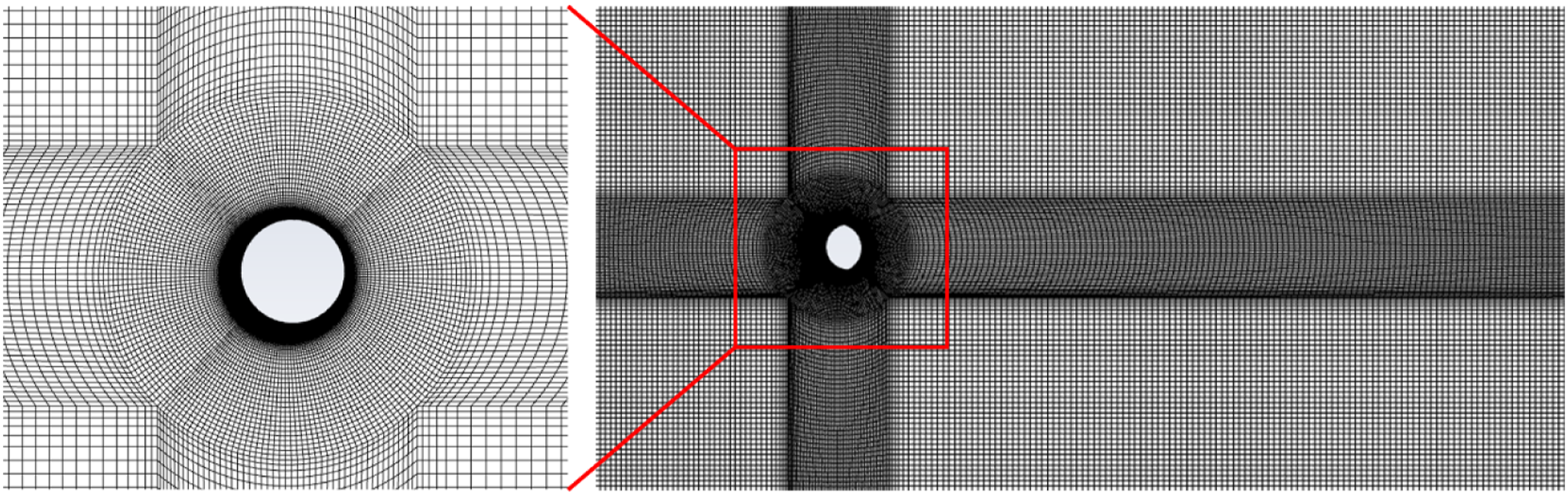
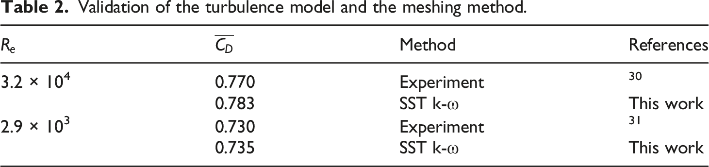
Validation of the turbulence model and the meshing method
Validation of the turbulence model and the meshing method.
Validation of the grid independence
To validate the grid independency, different grid sizes are selected. For smooth cylinder, refinement is done near the boundary layer. Therefore, grid independence test has been conducted for
Simulation results of drag coefficient
For the purpose of illustrating the effect of groove surface on aerodynamic performance, the time series of the instantaneous drag coefficient for the smooth surface and the surface with grooves at The instantaneous drag coefficients at The instantaneous drag coefficients at 

Flow field analysis
When the fluid passes through an object, it experiences a drag force, which usually consists of friction and pressure. 32 The direction of these two forces is opposite to the direction of the fluid. When the flow velocity near the wall decreases to close to zero under the action of these two forces, the friction also approaches zero, but the pressure still exists. Therefore, the slower-moving fluid near the wall stops or reverses direction, which is known as boundary layer separation. 33 The most obvious effect of fluid separation from the wall is to generate additional drag. Therefore, drag reduction can be achieved by suppressing or eliminating separation.34,35
Pressure distribution
The pressure distributions of smooth and grooves surface are simulated at Cloud picture for the pressure.
Vorticity distribution
The shedding of vortex in the cylindrical wake can be observed by vorticity contours. The vorticity distributions at Cloud picture for the vorticity.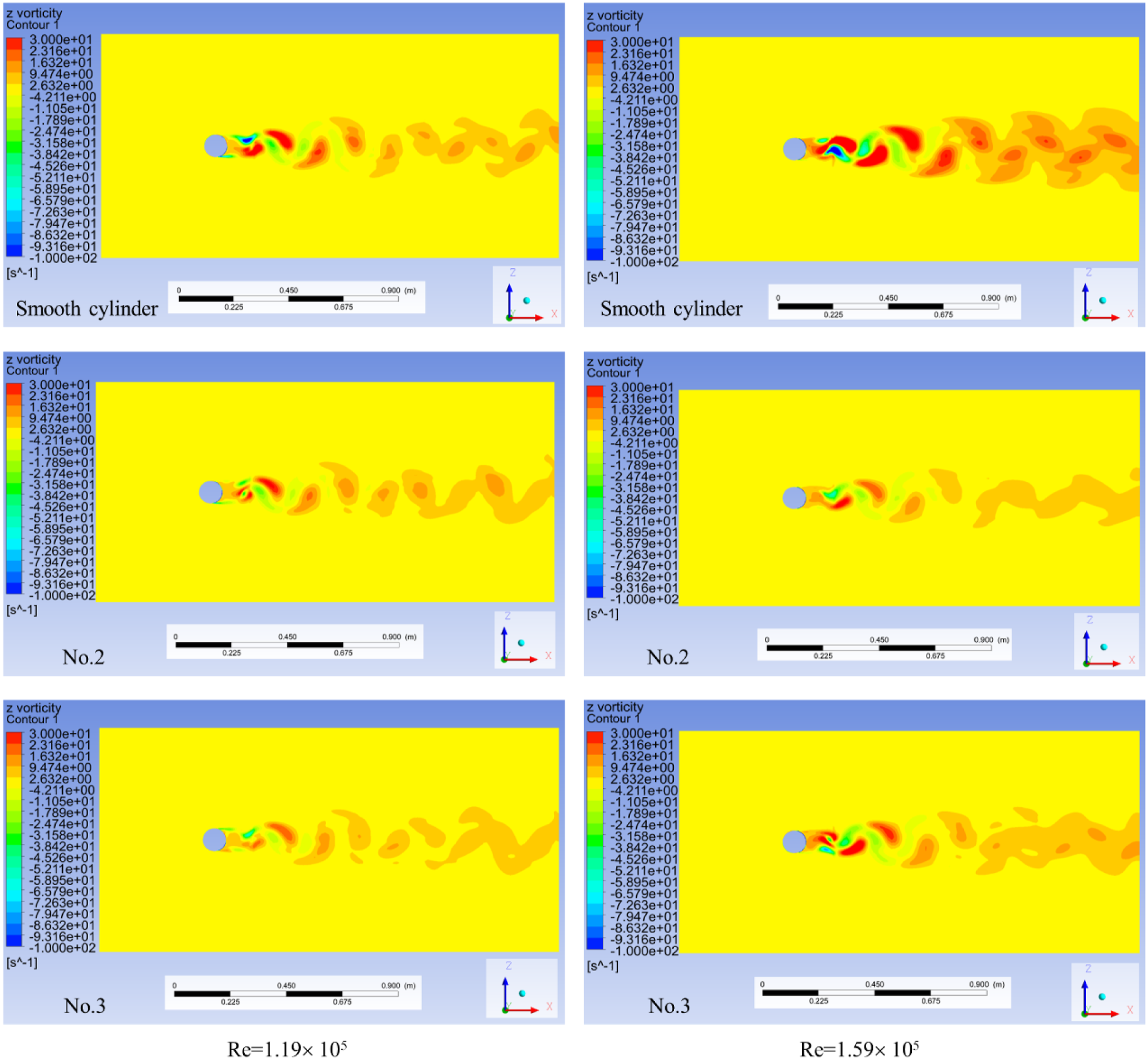
Turbulent distribution
The turbulent kinetic energy distributions at Cloud picture for the turbulence near the cylinder surface.
Conclusion
This paper presents an experimental study and numerical simulation on the drag reduction from a cylinder covered with smooth fabrics and grooved fabrics. The aerodynamic results of fabrics are compared with the flow over a nude cylinder in the wind tunnel. The drag reduction mechanism is investigated from the aspect of the pressure, vorticity, and turbulent kinetic energy by numerical simulation.
Through wind tunnel experiment and numerical simulation, the drag reduction performance of smooth fabric and grooved fabric is compared. The results indicate that the drag coefficient of the smooth fabric is almost the same as that of the nude cylinder, however, the fabric with micro-groove structure exerts a distinct characteristic on drag reduction behavior. These fabrics are very helpful to reduce the drag of athletes in high-speed sports such as cycling and short track speed skating, which can improve the performance of athletes.
The results of the flow field analysis suggest that the pressure difference between the front and back of the cylinder is smaller, the vortex shedding is inhibited more effectively, and the turbulent kinetic energy is more compared to those on the smooth surface. These effects can be conducive to delay the separation of fluid and wall, so as to reduce drag.
Abbreviations
Freestream velocity
Air density
Dynamic viscosity
Reynolds number
Drag force
Reference area
Drag coefficient
Drag impact
Pressure
Coefficient of kinematic viscosity
Footnotes
Declaration of conflicting interests
The author(s) declared no potential conflicts of interest with respect to the research, authorship, and/or publication of this article.
Funding
The author(s) disclosed receipt of the following financial support for the research, authorship, and/or publication of this article: The project of Shanghai Committee of Science and Technology, China (19dz1200702).