
Abstract
For improving the performance defects of traditional heald frame, the carbon fiber reinforced composites was applied to technical upgrading of the heald frame. On the basis of the theory analysis of composites laminates, the symmetrical ply scheme suitable for manufacturing of the heald frame in overall laminated was constructed, and a type of parametric program for finite element modeling was developed by ANSYS Parametric Design Language (APDL). The optimal mathematical model of the composites heald frame was proposed, and then the thickness parameter (t) and direction parameters (α, θ) of fiber layer were dynamic optimized by using of Sub-problem method. The work increased the fundamental frequency (ω1) of the heald frame by 10.38%. Besides, the harmonic response frequency was also increased from 48.41 Hz to 53.77 Hz, which conductive to further improve dynamics properties of the composites heald frame. This paper provides technical guidance for innovative design of new heald frame, and is helpful to solve the problem of speed matching between heald frame and high-speed loom.
Introduction
Heald frame is an important basic component of the textile machinery, its dymanics performance will directly affect the weaving efficiency and fabric quality. In recent years, with the rapid progress of modern woven technology, the speed of new shuttleless looms (such as air-jet loom, water-jet loom) has reached 1800r/min, at the same time, its weft insertion rate has also increased to 2000m/s. 1 In this case, the traditional heald frame can no longer meet the production requirements of the new loom. For example, when the loom crankshaft runs continuously at 800r/min, the heald frame made by aluminum alloy is prone to fatigue cracks, and even causes frame fracture in severe cases, which is not conducive to safe production and stable operation of loom.
Since the first industrial revolution in the 1860s, cotton textile machinery has been constantly evolving and innovating. During this period, the development of heald frame mainly experienced three stages: wood, iron and aluminum alloy. After entering the 21st century, with the rapid development of new materials, new technologies and modern design methods, the design and development of heald frame are also constantly innovating, the most representative of which is the new generation of heald frame made of composites material. Compared with the traditional heald frame, its comprehensive performance has been greatly improved. 2 The new composites heald frame can not only effectively reduce the technical failure rate of the shedding system, but also greatly reduce the vibration and noise, improve the workshop environment, which is beneficial to the physical and mental health of textile workers.
For a long time, some famous textile enterprises and manufacturers are all committed to the research and development of new heald frame, and they have got significant progress in the improvement of structure and material innovation of heald frame. For example, Swiss Grob successfully developed a kind of high modulus carbon fiber reinforced composite material and steel hybrid structure heald frame (WXS heald frame). Experiments show that the new heald frame has the characteristics of light weight, high strength and small vibration. The new carbon fiber heald frame introduced by Steel Heddle in the United States has greatly improved its performance, which can well meet the working requirements of high-speed jet loom. 3 Besides, a new type of heald frame with small vibration, low noise and low energy consumption was developed by Shenzhen Tailun Co., Ltd Using carbon fiber and basalt fiber reinforced epoxy resin, with its service life was 3–4 times longer than that of aluminum alloy heald frame.
In the technical exploration of composites heald frame, some industry technicians and college teachers and students have also done a slew of fruitful research work. For example, Lee D G, et al. (Korea) carried out theoretical calculation and experimental research on carbon fiber composites heald frame by using stiffness replacement method, finite element method, vacuum bag method and hammering method. 4 Zheng G, et al. (Korea) designed and developed a composites heald frame suitable for high-speed air-jet looms by improving its weight and structural rigidity. 5 Sun L, et al. (China Textile University) calculated and analyzed the working performance of the heald frame made of carbon fiber/epoxy composites, aluminum alloy and carbon steel. 6 Huo F L, et al. (Tianjin Polytechnic University) applied hybrid sandwich structure to the manufacture of a new heald frame, and studied the influence of different laying schemes and different reinforcement materials on the vibration performance of the heald frame. 7 Han B B, et al. (Xi’an Polytechnic University) carried out the dynamic design and analysis on the heald frame, and clarified the dynamic characteristics of the heald frame made of aluminum alloy, carbon aluminum composites and carbon fiber composites. 8
In recent years, although some composite heald frame products have appeared in the market, from the perspective of technical status and market scale, the development and practical application of this new heald frame are still in its infancy, and there is still a long way to go before the industry promotion. In the long run, the application of composites material in the design and manufacture of heald frame is the main development trend of new heald frame. Therefore, in order to effectively improve the weaving performance of loom system, the paper applies high performance composites to technical upgrading of heald frame, and the optimization mathematical model and design program aiming at improving the dynamic characteristics of heald frame are developed. Finally, by modifying the key shape parameters such as fiber layer thickness and laying angle, the dynamic optimization and structural lightweight of the composites heald frame are realized, which is helpful to solve the problem of speed matching between heald frame and high-speed loom.
Materials
Mechanical property of carbon fiber.
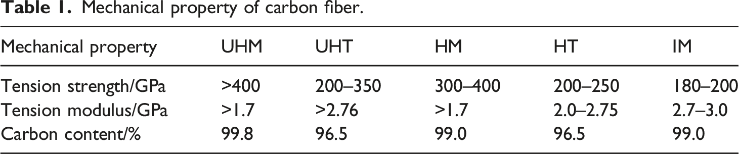
A large number of practical applications show that this new composites made of special fibers not only has high specific strength and specific modulus, but also has good fatigue resistance and designability. 10 The material now has been widely used in aerospace, automotive industry, biomedicine and chemical machinery and many other industrial fields.
Heald frame is the core moving part of loom shedding system. In the weaving process, the heald frame reciprocates in the vertical direction with linear speed v, as shown in Figure 1. Thousands of yarns are rapidly separated when the pull-down of heald frame are formed shedding. The shuttle will push weft through the shuttle port with a certain width to complete the weft insertion operation, and then the weft is tightened by the swing of the reed to form the fabric.
11
The warp and weft yarns are continuously overlapped and the formed fabric is wound round by round on the cloth roller. Weaving principle of the fabric.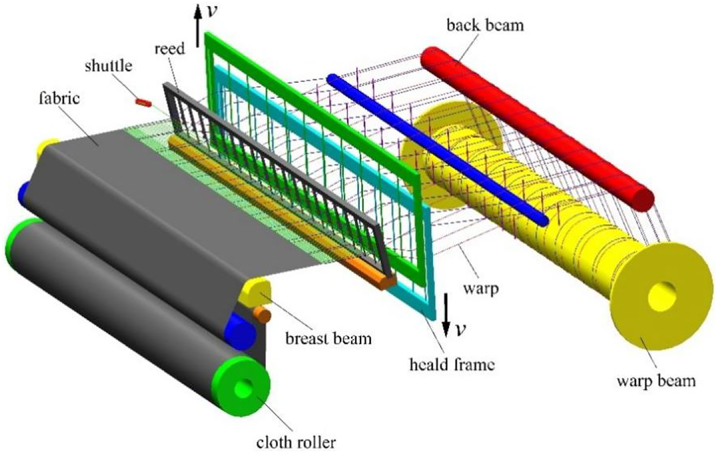
With the high-speed reciprocating motion of the heald frame over a long period of time, it can lead to a series of problems that are not conducive to weaving production under actual working conditions, such as fatigue damage, vibration noise and yarn tension fluctuation, which not only restricts the speed increase of the loom to a great extent, but also easily causes shedding technology failure and fabric defects.12,13
Actually, with the high-speed and high-precision development of modern looms, the performance of heald frame is required to be higher and higher at present. How to solve the problem of speed matching between the heald frame and modern loom is always a hot issue and key direction of textile industry at home and abroad. Under this background, the application of carbon fiber composites with excellent mechanical and physical properties to the design and preparation of heald frame, on the one hand, it can not only greatly reduce the inertia load of shedding mechanism, but also effectively suppress the vibration and noise of loom system, so as to improve the working environment in weaving workshops and benefit the physical and mental health of workers. On the other hand, it can effectively solve the performance defects of traditional heald frame from technical level, so as to meet the production requirements of modern high-speed loom. Therefore, the heald frame made of carbon fiber composites can meet the development expectations of advanced weaving technology.
Theoretical basis
Constitutive relation
Unidirectional laminates is the most commonly used structure of carbon fiber reinforced composites. Laminates is generally made of unidirectional prepreg, as shown in Figure 2. The thickness and direction of the fiber on each layer prepreg can be arbitrarily set according to bearing conditions. With the resin matrix material as the intermediate binder, the prepregs of each layer are stacked and bonded in a certain order to form the most basic laminates in composites. Fiber layer of laminates.
According to the theory of material mechanics, the elastic modulus E
x
along the length direction of fiber is greater than E
y
and E
z
which along transverse. When E
x
≠E
y
≠E
z
, the material is orthotropic. But in vertical plane of the fiber, the mechanical properties of the material are generally considered to be isotropic (E
y
=E
z
), and now it is the transversely isotropic material. In order to accurately calculate the mechanical mechanism of laminates, the elastic constitutive relation of the laminates should be corrected in practical application, as shown in equation (1).
14
The equation defines the stiffness matrix along and normal to the fiber direction of a particular laminate, and it is also the constitutive relation of a single laminate made of the transverse isotropic material.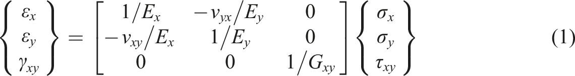
In the equation (1): ε x , ε y -Main strain; γ xy -Shear strain; ν xy , ν yx -Principal Poisson ratio; G xy -Shear modulus; σ x , σ y -Principal stress; τ xy -Shear stress.
It should be noted that the constitutive relation shown in equation (1) can be established only when the coordinate axis direction is consistent with the main direction of the material. Under this condition, the coupling term between normal stress and shear strain is zero. If the coordinate axis along other directions, all elements of the flexibility matrix are not zero, and now there will be coupling terms between the normal and tangential components.
Bending and coupling effects
The stress of the laminates along the x, y and z axis can be determined by its strain. For example, according to equation (2), the stress σ of the laminates at any position on z-axis can be calculated. It should be noted that since the stiffness of laminates is related to its material properties and fiber direction, the same x-y axis must be used as a reference when calculating the stress of the laminates, and the direction of x-y axis can be set arbitrarily.
In the equation (2):
The analysis of the laminates structure and its stress distribution shows that the sum of the stress (σ) in z-axis direction must be equal to the internal force (N) in the unit width.
15
Therefore, the sum of stress N on each layer of laminates can be expressed by the midplane strain ε0 and curvature r, as shown in equation (3).
In the equation (3): σi-Stress on the i-th layer of laminates; zi-Distance from midplane to the bottom of the i-th layer of laminates.
After integral operation of equation (3), it can be rewritten as another form, as shown in equation (4).
In the equation (4): A-Tensile stiffness matrix, as shown in equation (5), and the term reflects the effect of tensile strain ε0 to internal force N in the middle plane;B-Coupling stiffness matrix, as shown in equation (6), and the term reflects the effect of curvature r to internal force N in the middle plane.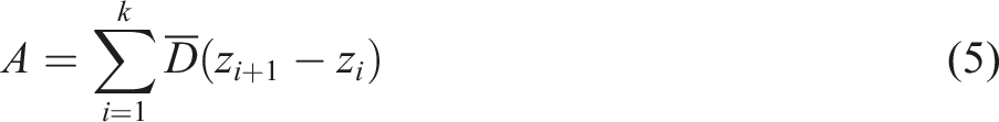

The classical laminate theory is a generalization of the bending theory of uniform plate. Therefore, the bending moment and torque on the cross section of the plate must be considered in the analysis and calculation. As shown in Figure 3, the moment vector M of the standardized internal force couple acting on the x and y can be expressed as the form shown in equation (7). Bending moment and torque on a single-layer laminate.

Since the sum moment of the internal force couple within the unit width must be equal to the moment caused by the internal stress in the laminate, the vector M can be expressed in the form shown in equation (8).
In the equation (8): h-Thickness of laminate; D-Bending stiffness matrix, as shown in equation (9).
According to the above derivation, the relationship between variables N, M and ε0, r can be established as a matrix form, as shown in equation (10). It can be seen that there is a coupling effect between the tensile and bending of the laminate.
Failure criteria
The ideal failure criteria should use as few failure parameters as possible, which is easy to realize for isotropic materials. Because carbon fiber composites have significant anisotropic characteristics, and its failure is closely related to the direction of load, in practice, more parameters are needed to describe the failure state of composite heald frame. Although many failure criteria for composite structures can be found from existing research reports, there is no a universal criteria so far.
It can be seen from the published literature that the damage possibility of carbon fiber composites is generally evaluated by the stress of single-layer laminate. Tsai-Hill criteria is a widely used method in practice, as shown in equation (11), it means that when the sum of the items on the left of the formula is equal to or greater than 1, the single-layer laminate is damaged.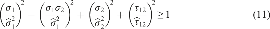
In equation (11):
The failure criteria is also applicable to the heald frame model in this paper, but only in the conditon of static analysis. Besides, It should be noted that this paper mainly studies the dynamic characteristics of the carbon fiber composite heald frame, so the focus is on the natural frequency and vibration mode of the heald frame, which is obviously different from the static analysis.
Parametric modeling
Structural analysis
Although the heald frame can be divided into different types according to loom model and material, the overall structure of any heald frame adopts the form of plane frame. As shown in Figure 4, the main structure of the heald frame is assembled from the crossbeam and side rails, and the other components are installed on the crossbeam or side rails according to their functions and positioning dimensions, such as guide board, heald clip, heald rod and heddle, etc. Structure diagram of heald frame.
In the process of shedding formation, due to the continuous influence of impact load and yarn tension, the heald frame will inevitably vibrate and deform when moving at high speed. In order to ensure the smooth operation of the shedding system, the stiffness and strength reserve of the heald frame must be sufficient. 16 The ideal structure of heald frame should have excellent properties such as light weight, high strength, low vibration and noise.
Laying method of fiber
The plane frame structure of heald frame can well adapt to the laminated manufacturing process of composites laminates, so the laminates used in heald frame can be constructed by integral lamination. In order to avoid the mechanical coupling effect of asymmetric laminates, a symmetrical paving scheme is adopted to design composites laminates suitable for heald frame. As shown in Figure 5, the single laminates is composed of eight layers of carbon fiber, the thickness of each layer of fiber is 0.2 mm, and the fiber laying direction is [0/45/-45/902/-45/45/0]. Fiber paving scheme of laminates.
Property parameters of the material.

Finite element model
The thickness and laying angle of fiber layer will greatly affect the actual mechanical properties of laminates.
18
In order to realize the parametric design of composites heald frame, the key shape parameters of laminates are set as modeling variables, as shown in Figure 6. If the thickness of each fiber layer is represented by the variable t, the total thickness of single laminates should be 8t; Keep the fiber laying angle in the horizontal direction (0o) and vertical direction (90o) unchanged, and used α and θ as the angle variables, it represents the laying direction of 45o and −45o fiber layers respectively, thus the fiber laying angle can be defined as [0/α/θ/902/θ/α/0]. Modeling parameters of laminates.
The composites element Shell181 in ANSYS was used for finite element modeling and simulation calculation of the laminates. As shown in Figure 7, the element Shell181 contains four nodes (I, J, K and L), and each node has six degrees of freedom. Therefore, the element has high simulation accuracy and equivalence, and is suitable for simulating thin to medium thickness of composites laminates shell or sandwich structures. Element geometry of Shell181.
In order to facilitate the parametric modeling and optimization design of heald frame, its structure needs to be properly simplified. Therefore, some unimportant parts such as heald rod, heald clip and heddle are ignored in the modeling process. The parametric finite element modeling program of heald frame driven by design variables t, α and θ is developed by using ANSYS Parametric Design Language (APDL). On this basis, the mesh model of 230 cm width heald frame is generated through APDL command flow. As shown in Figure 8, the heald frame is bonded by eight symmetrical laminates. Each laminates contains eight layers of carbon fiber, and the laying thickness of each layer is 0.2 mm, so the initial design thickness of the heald frame is 12.8 mm. Parametric finite element model of composites heald frame.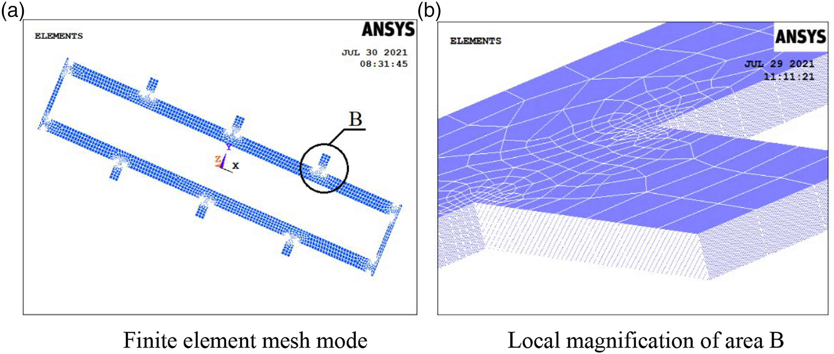
Modal analysis
Dynamics equation
As the theoretical basis of structural dynamics problems, modal analysis can provide a powerful reference for the evaluation of dynamic characteristics of the heald frame. The free vibration differential equation of the heald frame is shown in equation (12). According to the theory of dynamics, there is little effect on the natural frequency and mode shape of the structure which from damping. Therefore, ignoring the damping effect, and now the dynamic equation of the heald frame is shown in equation (13). The equations of equation (13) are a set of coupled second-order homogeneous linear differential equations with constant coefficients.

In the equation (12) and equation (13):M-Mass matrix;C-Damping matrix; K-Stiffness matrix; t-Time variable;δ (t)-Vector of node displacement, its is a function with time as its argument; .δ(t)-Vector of node velocity; .δ(t) Vector of node acceleration.
To solve equation (13) by means of linear transformation, modal coordinates f(t) must be defined, as shown in equation (14).
In the equation (14): δ i (t)-Physical coordinates of heald frame in the i-th vibration mode; u i -The i-th vibration mode of heald frame.
After substituting equation (14) into equation (13), a new equation will be obtained, as shown in equation (15). According to the vibration theory, when the heald frame vibrates freely, the amplitude of its each node is not all zero, so there is a non-zero solution in equation (15). Therefore, the coefficient determinant of equation (15) is equal to 0, as shown in equation (16), which is called characteristic equation or frequency equation of the heald frame vibration system.

In the equation (15) and (16): ω2 i -System eigenvalue; ω i - The i-th natural circular frequency of heald frame, rad/s.
The value of ω i can be calculated by determinant, and the equation (15) is decoupled by using the orthogonality of vibration mode after substituting ω i . On this basis, the vector of vibration mode u i for the heald frame under ω i can be calculated, which is a group of constants that are not all zero.
If the degree of freedom of the vibration system is i, the relationship between natural circular frequency will be ω1<ω2<…<ω i , and the minimum frequency ω1 is called the fundamental frequency. For many practical vibration problems, ω1 is not only the most important dynamic parameter, but also the key indicator to measure the vibration resistance of the structure. 19 When the heald frame vibrates freely, its arbitrary natural frequency f i =ω i /2π, and now the unit of f i is Hz.
Natural frequency

On the basis of the free modal analysis of composite heald frame, the natural frequencies of order 1–3 are extracted by Block Lanczos method, and compared with wood, iron and aluminum alloy heald frames with the same width, as shown in Figure 9. According to the dynamic theory, the higher the natural frequency, the stronger the anti-vibration performance of the structure. Obviously, the heald frame made of carbon fiber composites has great advantages in dynamic performance compared with others. Therefore, the effect of vibration and noise reduction will be better if carbon fiber composite material is used in the design and manufacture of heald frame. Natural frequencies of heald frame with different materials.
Under actual working conditions, the first-order natural frequency (f1) of the heald frame is most prone to co-frequency resonance, because the low order mode is more sensitive to the vibration response of the structure. 20 In order to avoid damaging the resonance of heald frame, the working frequency of loom spindle speed should be avoided f1 as much as possible. The f1 value of the heald frames from small to large as follows: iron (11.75 Hz), wood (17.84 Hz), aluminum alloy (19.96 Hz) and composites (41.13 Hz). It can be seen that the anti-resonance performance of the composites heald frame is 2–3 times that of traditional heald frame.
Vibration mode
The high-speed movement of heald frame is the main source of vibration and noise of loom system. When the frequency of the external interference load approaches or coincides with the natural frequency of the heald frame, it will resonate at the same frequency according to its natural vibration mode. According to the modal analysis theory, the natural frequency and material properties of the structure are important factors affecting its modal vibration mode. As shown in Figure 10 and Figure 11, there are obviously different between composites heald frame and aluminum alloy heald frame in their 1st∼3rd order vibration modes. Vibration modes of composites heald frame. Vibration modes of aluminum alloy heald frame.
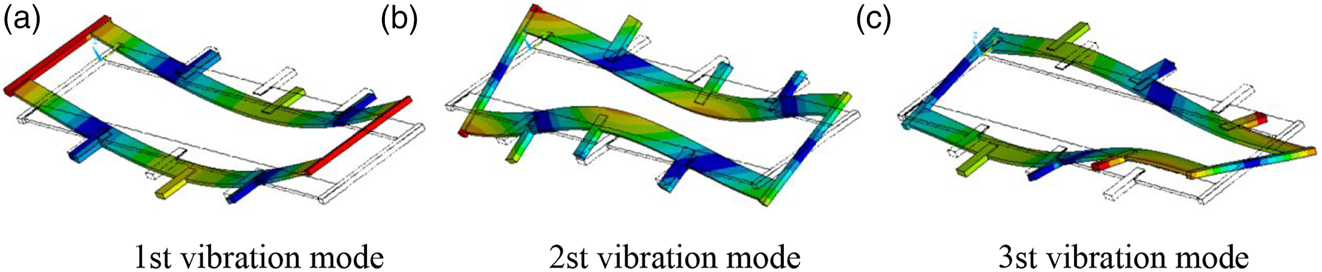
By further comparing the vibration mode, it can be seen that although the natural frequencies and vibration deformation of the two heald frames are different, their vibration modes are basically dominated by the bending or torsional deformation of the crossbeam, indicating that the crossbeam is most vulnerable to damage in the state of low-frequency resonance. Therefore, the structure of the crossbeam is particularly important for the vibration reduction design of the heald frame. In practical application, the strength and stiffness reserve of the crossbeam should be enhanced as much as possible.
Mathematical model of optimization
According to the constitutive relationship of laminates and its layer structure, the parameters (t, α and θ) will specially affect the mass and stiffness of heald frame. 21 Therefore, there is an internal functional relationship between these parameters and any order ω i of heald frame based on structural dynamics. As shown in equation (17), it is an important foundation for constructing the dynamic optimization mathematical model of the heald frame.
On the basis of the design variables (t, α and θ), an optimization mathematical model aiming at improving the fundamental frequency (ω1) of heald frame is constructed. As shown in equation (18), it can be achieved by changing the fiber ply parameters (t, α and θ) to control the parameter ω1, and finally exploring a group of optimal parameter combinations that can significantly increase ω1.
In the equation (18): ω1b- Optimal value of ω1; ω1k-The k-th optimized value of ω1, and ω1k=2πf1k; (t k , α k , θ k )-The k-th optimized value of design variables
Since the optimization principle of ANSYS system is to minimize the objective function, equation (18) can be rewritten according to the principle, as shown in equation (19). In this condition, the optimization goal is to improve the first-order natural frequency (f1) of the heald frame.
In the equation (19): f1b-The optimal value of f1; f1k-The k-th optimal value of f1.
The initial design parameters of laminates are: t=0.2 mm, α=45°, θ=315° (i.e. −45°). In order to facilitate the optimization calculation and result analysis, the fiber ply angle is defined in the counterclockwise direction, as shown in Figure 12. Obviously, the sampling interval of the fiber angle is set as follows: α∈[5o 85o], θ∈[275o 355o], and the variation range of fiber ply thickness is set as: t∈[0.1, 0.35]mm. Ply angle of the fiber.
Results and discussion
In this section, the optimal calculation was carried out based on Sub-problem method. Using this method, the relationship between design variables and objective function is constructed through curve fitting, and the optimization problem is transformed from constrained state to unconstrained state, which can effectively improve calculation accuracy and reliability of the minimization optimization process. 22 On the basis of running APDL program in ANSYS environment, some important results in curve format are obtained, which will provide discussion basis for dynamic characteristics of composites heald frame.
Optimization process and results
It can be clearly seen from the optimization process curves that the process curves of design variables (t, α, θ) and optimization objective (f1) eventually tend to be stable, as shown in Figure 13 and Figure 14, indicating that the optimization result has good convergence. Process curve of design variables. Process curve of optimization objective.

Optimized data of the heald frame.

Sensitivity of design variables
The relationship curve between design variables and objective function is shown in Figure 15. From the comparison of the curve shape, it can be seen that the first natural frequency (f1) of the heald frame is more sensitive to the variation of the thickness variable(t), which is relative to the angle variables (α, θ). Therefore, in determining variable α and variable θ, the fast optimization of f1 can be realized by controlling the variable t. Influence of design variables on optimization objectives.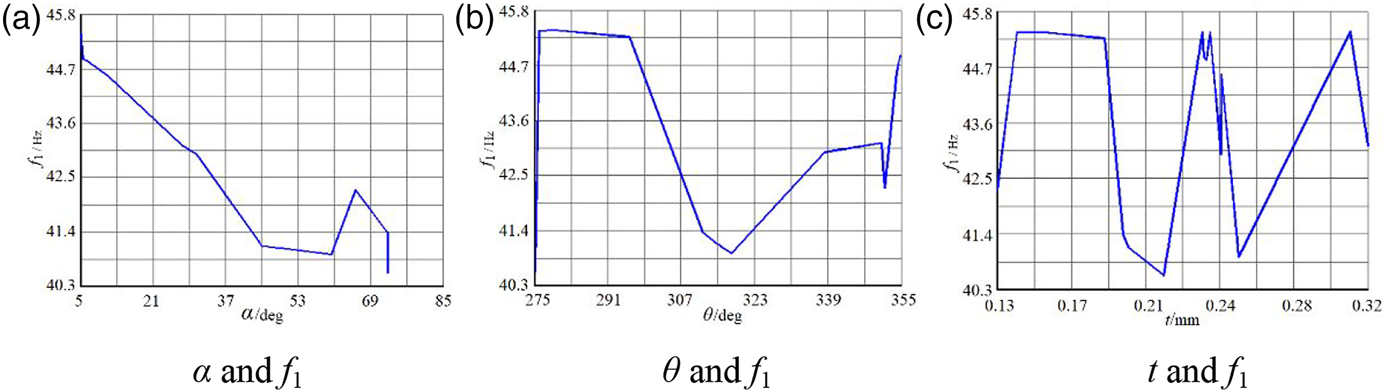
Harmonic response
Warp tension
During the operation of loom shedding mechanism, thereis a periodic impact on heald frame caused by dynamic warp tension. When the frequency of impact load is close to or coincides with natural frequency of heald frame, the loom system will produce strong vibration and noise. Through harmonic response analysis, the continuous dynamic characteristics of the heald frame can be effectively predicted and evaluated, which provides an important basis for vibration reduction design of the heald frame under harmonic load. 23
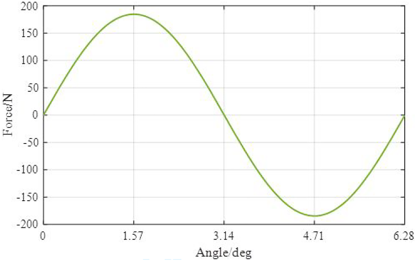
In this study, the variation of dynamic warp tension in the shedding system was simulated by harmonic load, as shown in equation (20) therefore, the dynamic warp tension can be approximately regarded as a sinusoidal load p(t) varying with time.
In the equation (20): P0-Amplitude of harmonic load;
When the shedding mechanism moves to limit position, the maximum tension of single yarn in the vertical direction is Ts=0.06 N.
24
It can be seen from the cotton textile manual that when pure cotton fabric of fine plain cloth is used as weaving object, the warp density ρf is 267.5 yarns/10 cm. According to equation (21), the maximum warp tension Tmax acting on the heald frame is 184.58 N, so P0=184.58 N. It is supposed that initial phase φ=0 and width d=230 cm. According to the results of free modal analysis, the forced frequency range should be set to [40 105]Hz. Therefore, the harmonic load p(t)=184.58sin (2π Curve of harmonic load.
Amplitude frequency characteristics
According to the actual connection of heald frame, two displacement constraints should be set for the lower crossbeam, as shown in Figure 17, and the node displacement U
X
=U
Y
=0 is defined. Since the crossbeam is most prone to vibration deformation, the harmonic load p(t) is used to excite in its maximum bending deformation area, as shown by the red arrow on the upper crossbeam, and the direction of the load is consistent with negative direction of the Y axis. Boundary conditions of composites heald frame.
The harmonic response analysis is carried out based on the constrained modal analysis, and the frequency sweep calculation of the composites heald frame in the range of 40–105 Hz is carried out by the Full method, and then the amplitude frequency response curves of the excitation area is obtained, as shown in Figure 18 and Figure 19. Compared with the displacement response amplitude before and after optimization, it can be seen that the vibration deformation of heald frame mainly occurs in Y direction. By comparison, the displacement response amplitudes in X direction and Z direction are very small, especially in Z direction, and its harmonic response can be ignored. Amplitude frequency response curve with no optimization. Amplitude frequency response curve with optimization.

By comparing Figure.18(b) and Figure.19(b), it can be seen that the harmonic frequencies of heald frame before and after optimization are 48.41 Hz and 53.77 Hz, respectively. The vibration modes of the heald frame close to two harmonic frequencies is shown in Figure 20, and its natural frequencies are 48.47 Hz and 54 Hz, respectively. Although the frequency values are different, their vibration modes are very similar, showing the bending vibration of the crossbeam. It is worth noting that the optimized design not only increases the harmonic frequency of heald frame by 5.36 Hz, but also reduces the harmonic response amplitude from 31.1 mm to 7.3 mm, indicating that the amplitude frequency characteristics of composite heald frame have been effectively improved. Vibration modes of heald frame under harmonic response frequency.
Vibration level
In actual weaving process, considering the speed matching contradiction between heald frame and high-speed loom, it is required that the heald frame must have the characteristics of light weight, low vibration noise, high rigidity and anti fatigue strength. 25 Carbon fiber composites have excellent mechanical and physical properties, such as high specific modulus, specific strength, strong fatigue resistance, etc. By replacing aluminum alloy with composites to manufacture heald frame, the weight of heald frame with the same width can be reduced by about 25%, which will greatly reduce inertia load and vibration noise of the shedding system, and this is the main reason why only carbon fiber composites are used for new heald frame.
From the simulation results of the theoretical model, it can be seen that the fundamental frequency of the optimized composites heald frame is 45.40 Hz, which is more than twice that of the aluminum alloy heald frame (19.96 Hz). Actually, in previous studies, the difference in dynamic performance between the two heald frames has been verified by experiment. For example, the impulse frequency response method was ever used to measure dynamic characteristics of the heald frame by Korean scholars Lee D G, et al., as shown in Figure 21, the natural frequency of the composites heald frame in the lateral direction is improved 43% compared with aluminum heald frame. Vibration test of impulse frequency.
Obviously, the vibration and noise reduction performance of the former is significantly better than that of the latter. Although the structure of the experimental heald frame is slightly different from the theoretical model in this paper, it uses carbon fiber composites with the same mechanical properties. Therefore, the vibration test results can also provide reference and support for our work.
Future work
Due to many factors such as technical difficulty, process complexity and R and D cost, the research theory, design method and preparation process for the overall laminatesd manufacturing of the heald frame are still immature, especially in the optimization of fiber layer parameters of composites heald frame, there are few in-depth research literature and valuable achievements.
In this paper, the design method and optimization idea of the composites heald frame were proposed, and several research results with theoretical reference value and practical guiding significance was obtained, which laid an important foundation for the development and technological progress of new heald frame.
For this research direction, future work should continue to explore sample trial production and experimental research of the heald frame, which based on current study in this paper, and it is also the key work to be carried out in the future.
Conclusion
The results of modal analysis showed that the heald frame made of carbon fiber composites had stronger vibration resistance compared with wood, iron and aluminum alloy heald frame. The bending and torsional deformation of the crossbeam were the main feature of the vibration mode of the heald frame. In practice, the strength and stiffness design of the crossbeam should be enhanced as much as possible.
An optimization mathematical model of the composites heald frame was set up, which provided a theoretical basis for dynamic optimation of the heald frame. On the basis of that, the dynamic optimization of fiber ply parameters (t, α, θ) was realized by using of Sub-problem method, and the optimal thickness t=0.31 mm, the optimal angle was [0/5.19/279.33/902/279.33/5.19/0]. The optimization result increased the fundamental frequency (ω1) by 10.38%, which therefore, effectively improved the dynamic characteristics of carbon fiber composites heald frame.
Besides, the harmonic response frequency of heald frame was increased from 48.41 Hz to 53.77 Hz through dynamic optimization, and the vibration amplitude of crossbeam in Y direction was also reduced. The results indicated that the amplitude frequency characteristics of the heald frame were further improved to reduce the vibration and noise of loom system.
In summary, this aspect of the research suggested that the heald frame made of carbon fiber composites has excellent mechanical and physical properties, and it is conductive to solve the problems of warp breaking, fabric defects, vibration and noise in the weaving process.
Footnotes
Acknowledgements
We like to thank all the participants and institutions for their technical support as well as all further partners supporting our research work within this application area.
Declaration of conflicting interests
The author(s) declared no potential conflicts of interest with respect to the research, authorship, and/or publication of this article.
Funding
The author(s) disclosed receipt of the following financial support for the research, authorship, and/or publication of this article: This work was supported by the Scientific Research Project of Education Department of Shaanxi Provincial Government(grant no. 15JK2177), and also funded by the Special Fund Project for High-level Talents of University(grant no. XJ20B09).