
Abstract
The shear thickening fluid (STF) treatment enhances the low and high velocity impact resistance performances of para-aramid woven fabrics for soft armour application. This research investigates the effects of important parameters on the STF add on and impact energy absorption with the aim to develop a hybrid soft armour. The STF add-on on ultra-high molecular weight polyethylene (UHMWPE) woven fabrics was varied by altering the silica particle size, dilution ratio of STF and padding pressure. The results of the full factorial design of experiment showed that the energy absorption is independent of the add-on. Further, a soft armour panel (SAP) was made from the STF treated woven fabric. The ballistic performance of the panel was evaluated in terms of back face signature (BFS) against a 9 × 19 mm lead core bullet and was compared to that of a weight equivalent untreated panel. A hybrid SAP with unidirectional (UD) laminates of UHMWPE as strike face layers and STF treated woven fabrics as backing layers was prepared, and the BFS was found to be equivalent to that of a SAP containing 100% UD laminates (∼30 mm). The results imply that a certain number of UD laminate layers can be replaced with STF treated flexible woven fabrics without compromising on the ballistic performance of SAP.
Keywords
Introduction
Soft armour panel (SAP) is a textile based flexible protective gear that provides protection against small arms like a revolver, pistol and handguns. At present, SAPs are made of multiple layers of woven fabrics or unidirectional (UD) laminates of para-aramid or ultra-high molecular weight polyethylene (UHMWPE) fibres.1–7 In recent years, UD laminates of UHMWPE have gained more attention due to its weight advantage and superior ballistic performance.
Over the last two decades, researchers have adopted several techniques to improve the bullet resistant jackets with respect to performance, weight and flexibility. Some of the noteworthy approaches include impregnation of high-performance fabrics with shear thickening fluid (STF),8–12 fabric surface treatment,13–16 growth of nanostructures on textile substrates,17–20 and hybridisation using different fibres and fabric structures.21–25 Among these, STF treatment and hybridisation, and a combination of both have been explored to a greater extent. For instance, Park et al.10,26 developed SAPs from different combinations of UD UHMWPE laminates and para-aramid fabrics, with and without STF treatment. It was concluded that the placement of STF impregnated fabrics as backing layers is beneficial in terms of ballistic performance and weight because the strategy offers enough time for the STF to trigger the thickening phenomenon.1,8,26 A similar observation was also reported by other researchers. 9 It is hypothesised that the placement of stiff materials at the front layers helps in deforming the bullet and placement at the back layers, aids in restraining the backward deflection of the SAP. On similar grounds, hybridisation with stiff polycarbonate sheets and steel meshes have also been explored as sacrificial strike layers for V50 analysis. 27 Further, logical sequencing and layering orientation have also been explored on different occasions with the sole intention of optimising the use of high-performance materials3,8 to prevent under or over designing of SAP with respect to the target performance. In this regard, UHMWPE is preferred to para-aramid due to lower density and higher speed of wave propagation in case of the former. Although the superiority of UHMWPE UD laminates is well documented in literature,3,28–32 however, its performance in combination with STF has not been explored thoroughly. An initial investigation was conducted by Mawkhlieng and Majumdar 8 using coarse and low-grade UHMWPE fabrics to study the effect of modulus. It was observed by Arora et al. 33 in their low velocity impact experiment that there is a strong dependence of efficacy of STF on fabric structure, an interaction that was not taken into consideration in most of the studies.
Further, the enhancement in the performance of STF treated fabrics logically questions the level of STF add-on that is required to gain positive outcomes. In the literature, the add-on spans over a wide spectrum with values as low as 2%34–36 to values as high as 237%. 37 Since performance gain is observed at all the different levels of add-on, it is therefore important to understand if more add-on translates to even better impact resistance. From the available literature, it is observed that the efficacy of STF treated UHMWPE woven fabrics against high velocity impact has not been explored in isolation. Further, the strategic design of hybrid SAP employing STF treated UHMWPE fabrics deserves more attention.
Thus, in the present study, STF add-on optimisation was studied through a full factorial design of experiments. From the STF treated UHMWPE woven fabric, a panel was assembled and was compared to a weight equivalent panel constructed from 100% neat woven fabrics of UHMWPE in terms of BFS. Additionally, a hybrid panel with backing of STF treated fabrics was compared with a 100% UD panel to observe if STF treatment helps in maintaining or reducing the BFS.
Materials and methods
Materials
UHMWPE yarns having a linear density of 400 dtex and UD laminates of UHMWPE were used in the present study. From the yarns, a balanced woven UHMWPE fabric having thread density of 40 × 40 inch−2 was manufactured on a CCI sample loom. The areal density of the fabric was 150 ± 5 g.m−2. On the other hand, the UD laminates with an areal density of 216 ± 8 g.m−2 contained UHMWPE filament sheets layered orthogonally one above the other in (0°/90°)3 pattern and consolidated between two layers of low-density polyethylene films.
For the STF add-on optimisation experiment, three sizes of silica nanoparticles were used: 100 nm, 300 nm, and 500 nm. Polyethylene glycol (PEG Mw 200) was chosen as the carrier fluid. Silica nanoparticles were obtained from Nippon Shokubai, Japan, whereas PEG 200 was procured from Merck Specialities Pvt Ltd. Ethanol was used as a diluent for STF to facilitate easy mixing and proper impregnation.
Fabric manufacturing
Fabric manufacturing was carried out according to the standard weaving protocol: sizing (coating), warping (beam preparation) and weaving. Sizing of yarns was done on a single end sizing machine using polyvinyl alcohol (PVA) as a film-forming agent, and the sized yarns were dried at 80°C. Warping and weaving were carried out on a single end warping machine and single rapier loom, respectively. Fabric sett of 40 × 40 inch−2 was used as optimised by Arora et al. 33 to obtain an areal density of 150 ± 5 g.m−2.
Preparation of shear thickening fluid
STF was prepared by dispersing a known amount of silica particles in PEG 200 such that the solid (silica) fraction was 0.65 by weight (w/w). The remaining 0.35 weight fraction was contributed by PEG 200. Three silica particle sizes were chosen: 100 nm, 300 nm and 500 nm and hence, three STFs were prepared- STF-100, STF-300 and STF-500. Prior to making the STF, the silica particles were oven dried for 2 h above 100°C to remove any volatile impurity or remnant moisture. The silica particles were initially dispersed in ethanol by using a high-speed homogeniser (17,400 rpm) and a probe sonicator sequentially for 5 min each. After the process, the ethanol dispersed silica was mixed with PEG 200 with the help of a homogeniser for 5 min and then with a probe sonicator for another 20 min. The prepared mixture of silica, PEG and ethanol was kept inside an oven at 120°C for 2 h to remove the ethanol. This resulted the STF that contains silica particles and PEG.
Impregnation of UHMWPE woven fabric with shear thickening fluid
To impregnate the UHMWPE woven fabric with STF, dilution of the highly viscous STF with ethanol was necessary. The PEG: Ethanol ratio was varied at three levels, namely 1:4, 1:6 and 1:8. A high-speed homogeniser was used to prevent agglomeration and to ensure the uniform dispersion of silica nanoparticles in the diluted suspension. Woven fabrics were impregnated with the diluted STF solution on a padding mangle keeping 3 m·min−1 surface speed of padding rollers and at three different squeezing pressures (2 bar, 4 bar and 6 bar) to vary the amount of STF add-on. Figure 1 shows the schematic representation of the STF impregnation process. Each fabric was passed twice through the nip of padding rollers and thereafter, the samples were kept in a hot air oven at 70°C for 30 min to evaporate the ethanol. Add-on (%) for each sample was calculated using equation (1). Shear thickening fluid impregnation of fabric by padding process.

Preparation of soft armour panels
Materials used for soft armour panels.

Configuration details of soft armour panels.


Stitching pattern and shot locations for woven fabric and UD laminates.
Rheological analysis of shear thickening fluids
The STFs were evaluated for their flow behaviour using Anton Paar Physica MCR 51 stress-controlled rheometer using a parallel plate geometry with 0.3 mm gap. The diameters of the upper and lower plates were 25 mm and 50 mm, respectively. The test was conducted at three different temperatures, i.e. 15°C, 25°C and 35°C, and the shear rate varied from 1 s−1 to 1000 s−1.
Scanning electron microscopy
ZEISS EVO 15 Scanning Electron Microscope (SEM) was used to analyse the morphology of fibre surface, the cross-sections of woven fabrics and UD laminates as well as to determine the failure modes during ballistic impact. For failure mode analysis, small samples were cut from the striking point on the SAPs. For cross-sectional view, small samples were cut by using a sharp surgical blade and were mounted vertically on a stub with the help of silver tape.
Full factorial design for optimisation of shear thickening fluid add-on
Full factorial design and sample codes.

Tensile testing
The tensile testing of woven fabrics and UD laminates was conducted on a universal testing machine (Tinius Olsen) following ASTM D 5035. The specimens were cut in rectangular strips having 250 mm length and 25 mm width and were clamped between two serrated jaws at 75 mm gauge length. The test was conducted at a rate of extension of 300 mm·min−1. Five specimens were tested for each sample in standard atmospheric conditions for tropical region (25 ± 2°C temperature and 65 ± 4% relative humidity).
Dynamic impact testing
The dynamic impact testing was conducted for both neat and STF impregnated fabrics on a falling dart type impact tester (CEAST, Model: FRACTOVIS PLUS). An indenter of 12.7 mm diameter that was attached to a mass of 20 kg was made to fall freely on the samples with an impact velocity of 4.5 m.s−1, releasing impact energy of 200 J. Five specimens, each of 150 mm × 150 mm were tested for each set using ASTM D3763. The specimens were placed between the two circular annular jaws having a knurled surface that gripped the sample with a clamping force of 7000 N. The test set-up is shown in Figure 3. Dynamic impact testing set-up.
Ballistic testing
Ballistic testing set up
The ballistic testing was conducted according to NIJ 0101.06 standard, as shown in Figure 4. The distance between the universal mounting barrel and the target was kept at 5 m to ensure maximum bullet stability with a minimal air drag effect. Furthermore, the optical velocity measurement system was kept in the mid position (2.5 m) of the barrel and target. A submachine carbine (SMC) gun was used to propel the bullets (7.5 g, 9 mm diameter) at a velocity of 430 ms−1. Roma Plastilina #1® Grey moulding clay was used as the backing against which the SAPs were strapped using hook and loop fasteners in accordance to NIJ 0101.06. The hardness of moulding clay was calibrated before each test by ensuring that the depth of the indentation, when a steel sphere (1.043 kg weight and 63.5 mm diameter) was dropped on the clay, fell within the prescribed limit of 19 ± 2 mm. Ballistic testing set-up.
Results and discussion
Tensile properties
Figure 5 shows the stress-strain behaviour of UHMWPE woven fabric (W) and UD laminate (U). It is observed that the former exhibits lower initial slope of strain-strain curve, lower ultimate stress (0.64 N·tex−1) and higher strain at break (18%) as compared to the latter (stress of 0.86 N·tex−1, strain of 4.6%). Lower ultimate stress and higher strain at break in case of woven fabrics are due to the presence of undulation or crimp in the yarn which is completely absent in case of UD laminate. However, the toughness of woven fabric is higher than that of UD laminate because of the higher strain in the woven fabric arising from the removal of yarn crimp during tensile testing. Stress-strain curve of UHMWPE UD laminate and woven fabrics.
Rheological analysis
Figure 6 depicts the rheological flow behaviour of the STFs. All three STFs show discontinuous shear thickening behaviour. It is also observed that for given particle size, the viscosity drops with increasing temperature, a trend that is well documented in the literature. Additionally, among the different STFs, the critical shear rate reduces with increasing particle size. An interesting phenomenon which is presently termed as “span” (shear thickening plateau) is seen to be prominent in STFs with larger particle sizes of silica. It is generally observed that the span increases with increasing particle size and that it decreases with increasing temperature. At present, the significance of this zone is not fully understood. However, it is envisaged that as shear thickening spans over a range of shear rates, the benefit of high viscosity may be more exploitable for impact applications. Flow curves of STF-100, STF-300, and STF-500.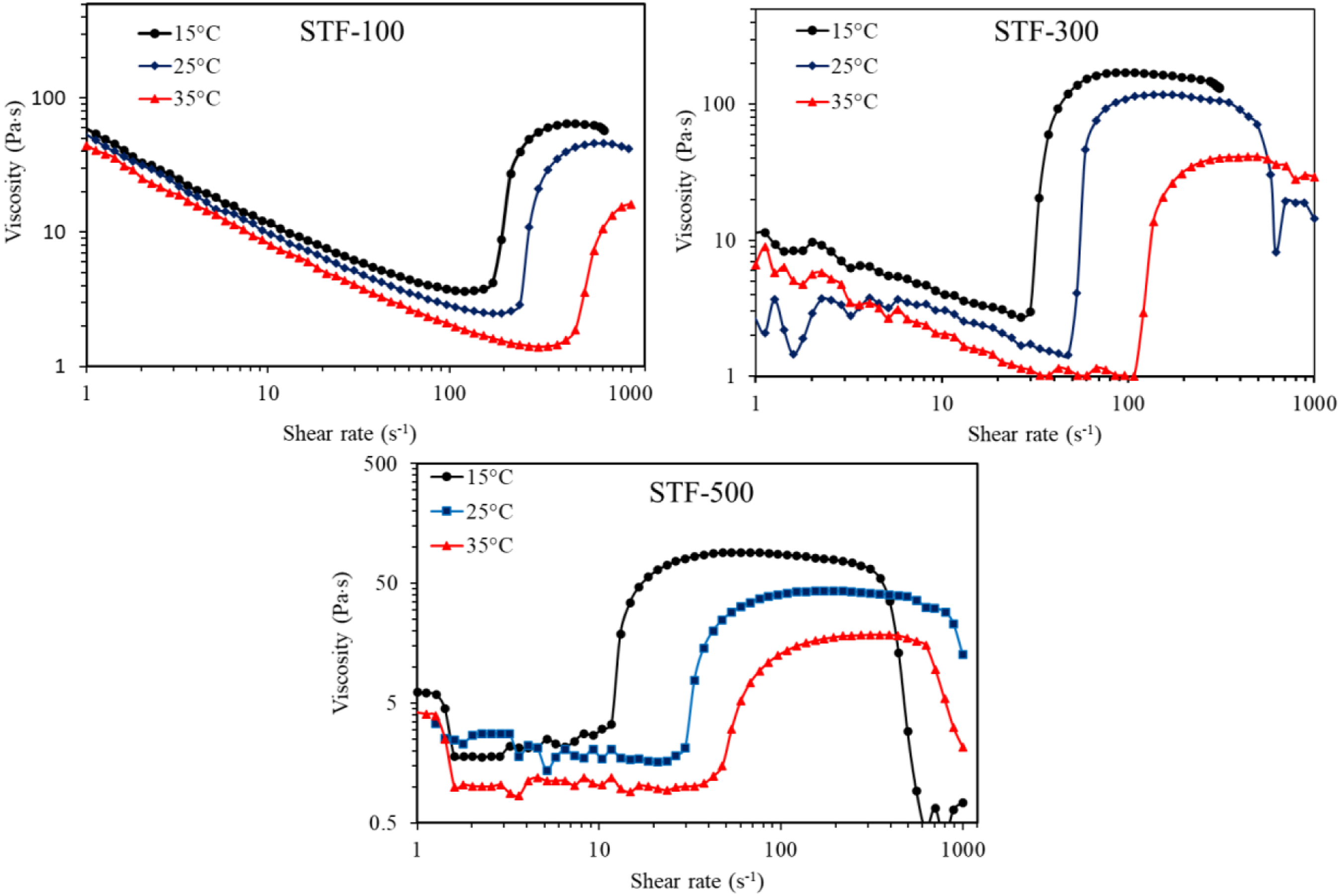
Optimisation of shear thickening fluid treatment parameters
ANOVA for shear thickening fluid add-on.

ANOVA for impact energy absorption.


Contour plot showing the effect of dilution ratio and padding pressure on add-on (LHS) and energy absorption (RHS): (a), (d) STF-100; (b), (e) STF-300; (c), (f) STF-500.
Table 5 reveals that the model considering the effect of the three considered parameters on impact energy absorption is statistically insignificant (p-value = 0.217). However, akin to the effect on add-on, dilution ratio seems to be statistically significant and the most effective parameter (p-value = 0.031). The effect of particle size is found to be statistically insignificant which may be attributed to the opposing effect of particle size on surface coverage and dilatancy both of which have role in influencing impact energy absorption. While looking at the energy absorption values at three different pressures, it is noted that the range of energy absorption varies from 41 J to 51 J at low pressure (2 bar), 39 J–49 J at medium pressure (4 bar) and 41 J–52 J at high pressure (6 bar). Therefore, it is observed that padding pressure is not playing any significant role on energy absorption. This may be due to the fact that low pressure induces surface coating of fibre and yarn by STF but low penetration inside the yarn and fabric structure. On the other hand, high pressure facilitates deeper penetration but less surface coating by STF.
Figure 8 depicts the scatter plot of STF add-on and energy absorption by UHMWPE woven fabrics. It is witnessed that while STF addition is beneficial for augmenting impact resistance, its undue add-on does not have any beneficial effect other than increasing the weight and cost. The independency is clearly highlighted in Figures 7(d)–(f) and 8 which show no distinct relationship between STF add-on and impact energy absorption. Therefore, the minimum add-on should be standardised to obtain the benefit of STF in terms of enhanced specific impact resistance, i.e. energy absorption as a ratio of areal density of STF treated fabric. Therefore, for the present study, 500 nm is chosen based on the shear thickening span as observed in the rheological analysis, whereas the highest level of dilution ratio (1:8) and padding pressure (6 bar) are chosen based on the result of the experiment design. Scatter plot of shear thickening fluid add-on and impact energy absorption.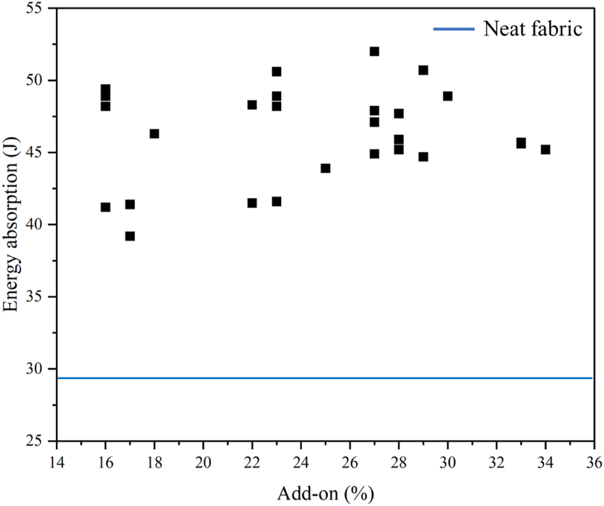
Energy absorption and deformation behaviour
Figure 9(a)–(c)show the energy absorption by neat, STF-100, STF-300 and STF-500 impregnated fabrics. All STF impregnated fabrics show higher impact energy absorption compared to the neat fabric. The range of improvement in energy absorption for STF-100, STF-300 and STF-500 impregnated fabrics, compared to neat fabric, is found to be from 43% to 79%, from 35% to 66% and from 51% to 75%, respectively. STF-100 and STF-300 impregnated fabric indicate less within-sample variation which can be observed from the smaller error bar when compared to STF-500. Figure 9(d) depicts the force and deformation behaviour of neat and STFs impregnated fabrics (1:4 dilution ratio and 2 bar pressure). The peak force of neat fabric is much lower (∼2000 N) than those of STFs impregnated fabrics. The impregnation of fabric with STF increases the inter-yarn friction. Besides, due to the dilatancy of STF, the entire fabric behaves coherently resisting the impacting force. Therefore, more force is needed to either break or push apart the yarns. It is conspicuous that the neat fabric has an elongated failure zone signifying the yarn pull-out whereas the failure of STF treated fabrics is more catastrophic. Energy absorption and deformation behaviour of STF impregnated UHMWPE fabric (a) Neat, (b) STF-100, (c) STF-300 and (d) Force deformation curve.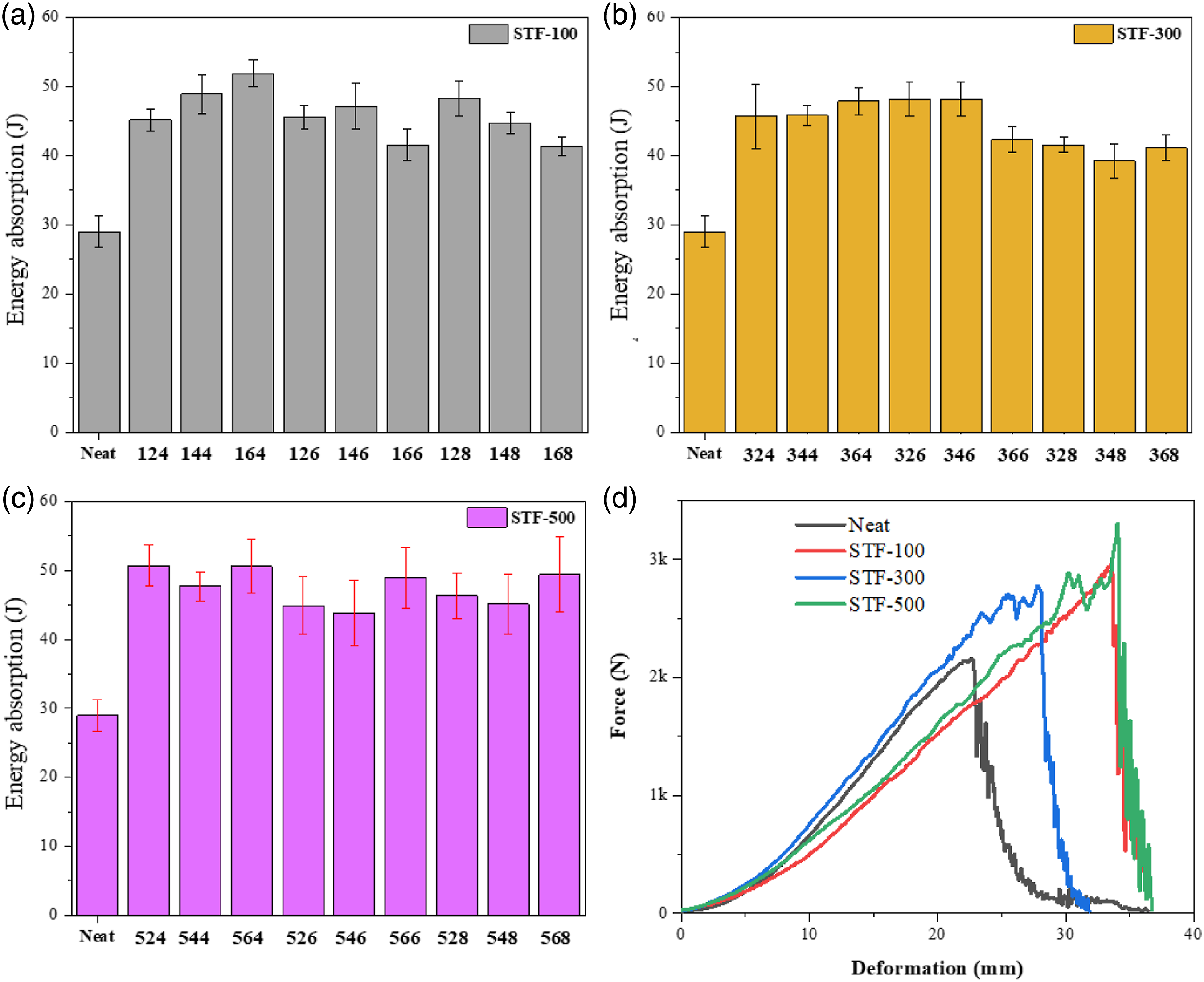
Scanning electron microscope analysis of shear thickening fluid impregnated UHMWPE
Figure 10 shows the scanning electron micrographs of neat and STF-100, STF-300, and STF-500 impregnated UHMWPE woven fabrics (1:4 dilution ratio and 2 bar pressure). It is seen that the nanoparticles are evenly distributed on the yarn surface and fabric interstices. It is noticed that the coverage of STF-100 on the yarn surface is better than that of STF-300 and STF-500. This can be attributed to the fact that even for the same add-on%, the total surface area is the maximum for 100 nm silica particle and the minimum for 500 nm silica particle. In case of STF-500, silica particles seem to cover the minimum area of filament surface. Scanning electron micrographs of fabric impregnated with Neat, STF-100, STF-300 STF-500.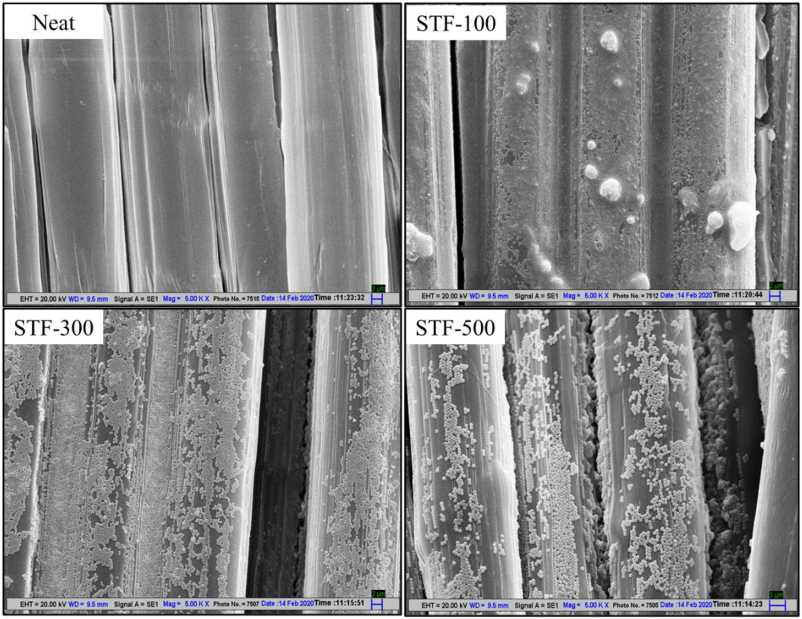
Ballistic performance
Back face signature
Hybrid soft armour panels configuration details.

Soft armour panels after ballistic evaluation.
Failure mechanisms
Figure 12 depicts the cross-section of woven and UD laminates, along with the schematic of failure mechanism of woven fabrics and UD laminates. In the case of the UHMWPE woven structure, the yarns are arranged in warp (0°) and weft (90°) directions. In other words, it can be postulated that woven fabrics are thick orthotropic membranes of UHMWPE yarn assemblies having crimp as seen in the SEM images. The schematic shows that the bullet impacting the woven fabric-based SAP deforms minimally as the resistance offered by the woven fabric is less. This is because the bullet follows the path of least resistance (inter yarn spacing) and waviness (crimp) in the yarn. Contrary to this, UD laminate is an arrangement of straight crimp-less filaments laid parallel, one over the other orthogonally as seen from the SEM micrographs. In case of UD structure, the filament assembly creates a net like structure of very thin orthotropic membrane. From the schematic, it can be seen that the bullet impacting on the SAP made from UD laminates deforms more extensively, resulting in less stress concentration at the point of impact. Besides, the absence of crimp also facilitates the faster travel of the stress wave away from the impact point. Therefore, the bullet gets trapped after penetrating a few layers of UD laminate. Failure mechanism: (a) woven fabric; (b) UD laminate.
Failure mode analysis
Figure 13(a)–(c) show the electron micrographs of failure zones at the front layers of SAPs made from neat and STF treated UHMWPE woven fabrics and UD laminates. Figure 13(a) depicts the partial melting and fusing of multifilaments in the woven fabric due to the lower melting point (155°C) of UHWMPE fibres. Figure 13(b) shows the failure behaviour of STF impregnated woven fabric. It can be seen from the failure zone that the silica particles present on the STF impregnated woven fabric enhances the coefficient of friction between the yarns and filaments. Partial melting and fusing of filaments is also visible in this case. The failure mode of UHMWPE UD laminates depicted in Figure 13(c) reveals similar observations to that of the woven fabric with additional evidence of delamination of cross ply layers and bead formation due to fusing. Similar types of failure modes of different grade of UD laminates have also been reported by other researchers.3,39–42 Scanning electron micrographs of front layer of SAP: (a) neat woven fabric (b) STF impregnated woven fabric (c) UD laminate.
Conclusion
Influence of process parameters (silica particle size, padding pressure and dilution ratio) for STF application on UHMWPE woven fabrics has been investigated in this research by using a full factorial experimental design plan. Contour plots were generated along with ANOVA to explain the role of these parameters on STF add-on and impact energy absorption of UHMWPE woven fabric. It was found that the effects of silica particle size, padding pressure and dilution ratio were statistically significant on STF add on while only the effect of dilution ratio was statistically significant on impact energy absorption. Increasing both the padding pressure and dilution ratio resulted in the least amount of STF add on due to excess STF being squeezed out. Scatter plot of STF add-on and impact energy absorption showed no correlation within the range of add-on observed (16%–34%). All STF impregnated UHMWPE fabrics at low velocity impact tests showed significant improvement in energy absorption compared to neat fabric. Furthermore, the performance of neat and STF impregnated multi-layered SAPs were evaluated at higher impact velocity (430 ms−1). It was found that similar to the neat panel, STF treated panel of UHMWPE was also unable to stop the bullet from perforating. However, when the STF treated fabric layers were strategically placed at the rear side of an assembly of UHMWPE UD laminates forming a hybrid panel, all the bullets were stopped. Moreover, BFS obtained (∼30 mm) was similar to that obtained in SAP with 100% UHMWPE UD panel. Outcome of this research will be useful to design hybrid SAPs using UD laminate and STF treated woven fabrics to ensure ballistic protection as well as flexibility of soft armour.
Footnotes
Declaration of conflicting interests
The author(s) declared no potential conflicts of interest with respect to the research, authorship, and/or publication of this article.
Funding
The author(s) disclosed receipt of the following financial support for the research, authorship, and/or publication of this article: This work was supported by the SERB-FICCI and RIL and Defence Research (SERB-PM Fellow/CII-FICCI/Meeting/2018) and Development Organisation (DFTM/03/3203/ M/01/JATC).