
Abstract
The present study endeavoured to examine the tensile strength of the laminates, which were made of carbon/Kevlar hybrid reinforced fibre with carbon nanotubes (CNTs) post oblique impacts. Although a number of experimental investigations on tensile properties of CNTs have been already performed, the coupling effects of CNTs and oblique impacts on tensile strength have yet to be reported. Due to the superior elastic modulus, the advanced nano-fillers were chosen as reinforcement of the carbon/Kevlar hybrid fibre. The inter-ply woven fabric possess high strength and excellent toughness due to the carbon and Kevlar fibre respectively and therefore well suited for ballistic impact applications. In spite of the fact that the effects of direct impact is most detrimental and widely reported, the effect of nano-fillers on the tensile integrity of oblique impacted specimens are of primary interest as most impact events are random in nature. CNTs with 0.1–1.5% loading ratios are dispersed into the epoxy resin and intra-ply Carbon Kevlar hybrid fabrics composite plates are fabricated via hand layup process. A loading of minimum 0.1% to maximum 1.5% CNTs were dispersed into liquid epoxy resin. The reinforced epoxy resin was applied to carbon/Kevlar fabric composite by layup process. Inclusion of CNT revealed depreciating mechanical properties in terms of tensile toughness; however, the inclusion demonstrated a potential reinforcement in a high modulus/strength in composite laminate’s specimens. Findings indicated that 0.7% of CNT had maximum tensile toughness values; whereas, the highest values of Young modulus were followed by tensile strength at 1.5% CNT. Moreover, compared with other factors, the impact load had a great influence on its specimens’ strength, and the effects of angled targets on the impact load of the specimens as well as CNTs' value were mostly obvious. Consequently, this investigation may be considered as a practical basis for designing and optimising of CNT contents and possible angle degrees and analysing tensile behaviour after the impact events.
Keywords
Introduction
In aerial navigation industries, bird strikes as well as their impact consequences are controversial topics in spacecraft mechanisms, structures, materials, and manufacturing processes. To compound the situation, in case of any probable bird strikes, the lives of aircraft crewmembers and their passengers are at risk. According to the report of the Associate Administrator of Airports in 2012, over 219 people have lost their lives worldwide due to the wildlife strikes since 1988.1–3 Although, the reported number of annual animal strikes decreased from a number of 1793 in 1990 to 9622 in 2010, the birds were involved in 97.2% of the strikes.4–6 Accordingly, 70 percent of bird strikes occurred when the aircraft was at a height of less than 150 m elevation.6–8 Moreover, in 2019 Federal Aviation Administration’s report estimated annual bird strikes damages to commercial aircraft about $1.2 billion worldwide. The damages mostly affected engines, wings, aircraft’s body, and nose respectively.8–10
In the modern global economy, maintenance of industrial equipment has been increasingly become significant for the used structures in the different industrial plants. Therefore, embedding the CNTs into the matrix has been a common maintenance procedure in different technological industries, transportation, defence, space, and advanced manufacturers that may result in reduction of expenditures on manufacturing activities as well as on the development of production.10–14 One of the most used nanoparticles as reinforcement is the CNTs, which possess excellent mechanical properties such as the elastic modulus of (0.27–0.95) TPa, tensile resistance between 11 and 63 GPa14–18 and low specific mass. Since lightweight is one of the major goals that improves fuel saving,18–21 the mentioned properties of CNTs make them suitable to be used in aerospace structures. In consequence, reinforced elements, carbon fibres although they are relatively expensive, improve the strength as well as the rigidity of used materials in different industries such as defence, advanced manufacturing, and space.22–25
On the other hand, in comparison to carbon fibres, Kevlar fibres technologically offer a superior abrasive strength to materials, which this quality justifies their uses in the bullet-resistant vests.26–29 Moreover, in comparison to carbon fibres, Kevlar fibres are remarkably resistant in extremely high temperatures. This recent property of Kevlar fibres also justifies their application in marine technology sectors.30–32 Moreover, Kevlar fibres have validated the sensitivity or specificity of reinforcing matrix by CNT for tensile strength of post oblique impact on carbon/Kevlar® hybrid fabric.17–23 Accordingly, to perform an investigation about the effects of CNTs on carbon Kevlar hybrid fabrics, conducting a tensile test is necessary to recognise the strength of a material and specially to obtain the mechanical characteristics of materials after oblique impact tests. 17 Only few studies investigated the effect of high density of fibre on the composite behaviour in order to exploit it for the innovative products of spacecraft mechanisms, structures, materials, and manufacturing processes. As such, the current study examined the tensile strength of carbon/Kevlar hybrid laminates reinforced with carbon nanotubes (CNTs) subjected to oblique ballistic impact loads with varying CNTs loading ratio up to 1.5% as larger amount of CNTs will result in agglomerations.
Method and materials
The procedure of performing the study, which consisted of four steps. The first step is the fabrication of composite panels with eight layers of carbon-Kevlar hybrid by adding CNT into epoxy or neat epoxy. In the second step, samples were cut and resized to form two different groups, in other words, five samples for each test were fabricated. The first group of samples were used for tensile testing and the second group was used to resize the samples to conduct normal and oblique impact. 17 Step 3 is comprised of conducting the tensile strength tests according to ASTM D3039M-17, 24 which was applied to both groups of samples (post impact and intact specimens). Step 4 is the stage to collect the test results of 175 of the final produced samples. Last step is explicable in terms of investigation of the tensile strength data and microstructural analysis, which was performed to offer values so that industry processes could be experimentally accomplished.
Principally, performing tensile tests on the impacted specimens is rare in the field of mechanical testing. Importantly, one of the major topics of experimental investigation in the general field of materials science engineering is epoxy-CNT composites. However, a challenging issue, which requires more attention, is the manufacturing costs that according to the present experimental research is negligible


Additionally, firstly, CNTs and BYK®-9077 (as a solvent-free wetting and a dispersing additive) in ethanol environment were blended for 5 minutes. Then for agitation purpose, dispersing by an ultrasonic bath homogeniser (sonicator) with a fixed power of 25 Watts was applied to the mixture of CNTs with a surfactant for an hour. In the third step, for 10 min the mixture was added and blended with high shear blending homogenisers at 3500 revolutions per minute (RPM). This step was followed by 45-min sonication treatment. Importantly, the combination was then placed in an oven and remained at a temperature of 25°C for 48 h under a pressure of 1-Bar. This process was continued for another 24 h in a temperature of 80°C for degassing procedures (see Figure 1). Consequently, the hand lay-up manufacturing technique with MWCNTs in the type of liquid were used for fabricating composite. Finally, the laminates were allowed to cure in air for 48 h.17–23
In order to observe the failure mode and deformation patterns of the specimens, Scanning Electron Microscopy (SEM) images were used. Incidentally, for reducing the charge transfer resistance of the interface, the specimens were coated by a sputter coating for SEM (5% Pa and 95% gold). In addition, the coating process was applied to fabricate the initial catalyst layer in a separate vacuum chamber with ranging pressures of 10–1 to 10–2 bar(s). Initially, 1 kV voltage applied to the specimens, which were mounted on some round plates in the vacuum chamber, proceeding under calefaction status of the plates. Due to falling of the coating material in the form of rays on the specimens, electrical current was controlled at 20 mA for 150 s. Moreover, the thickness of the coating layers was 0.021 μm.41–44
The plies show much stronger and stiffer than the previous forms. The loads were transverse (90°) to the fibre direction when the applied loads were parallel to the fibres (0°).45–48 Therefore, the plies’ orientation was (0°), the thickness of all of them was equally 2 mm, and the density of all the specimens was about 1.71 g.cm−3.
Oblique impact test
Figure 2 illustrates the inclined target, all made of stainless steel, which could be rotated from zero to 40° with an angle indicator. The bullet trap features a spent bullet depository and ballistic rubber front panel, with a thickness of 12.7 mm as well as self-healing properties. The ballistic front panel could slow down the rounds, minimise the impact of noise, and lead dust generations.
17
Setup for oblique target at 0, 10, 20, 30, 40 degrees.
17

Tensile test
Test specimens were adopted from the composite laminates, which performed on five specimens for a single condition of testing. Unidirectional tensile composite laminates were divided into fibre and matrix directions according to ASTM D3039M-17, 24 which is used to measure the force required to break a polymer composite specimen and the extent to the specimen stretches or elongates to that breaking point. Basically, tensile tests produce a stress-strain diagram using to determine tensile modulus. Accompanying, fracture force of various specimens was calculated from the stress-strain curve.47–49 The tensile testing services frequently involve the breakage and deformation of specimens of the materials, which are called fracture mechanics test specimens to the ASTM specifications.24–26 The specimen size was 250×25×1 mm3 and the skin specimens did not slip and slide out of the grips while conducting the tensile testing.19,24,25,33
Tensile after impact testing scenarios of the impacted specimens were conducted in order to investigate the strength reduction (or residual tensile strength) after impact damage, using the Instron 6025 mechanical test machine with a crosshead speed of 0.1 mm/min and 100 kN load cell. The assorted composite specimens were investigated in the Universal Testing Machine (UTM). Moreover, the reinforced material was allowed to damage in order to discover the maximum tensile strength values. 19
Predominantly, testing methodology is critically elaborated as it is considered the pristine specimens by resizing the impacted specimens. Damaged samples in terms of shape are slightly bent, axial, or lateral wise. Therefore, this may impose additional stress during testing and discussed in the following results and discussion section.
Results and discussion
Figure 3(a) as a sample fracture shows the excellent adhesion between fibre and reinforced epoxy resins. This inconsistency may be due to the surface attributes of fibre. Similarly, the layer values demonstrate similar behaviour in comparison to the neat epoxy, as it is shown in Figure 3(b), respectively. Furthermore, a comparison of these two images reveals the amount of fabrics adhered resin. Moreover, Figure 3(b) shows the resin not only exists around the bundles but also appears within the fabrics. Likewise, this phenomenon indicates that high pressure due to lower thickness squeezes unfilled resin, which has more resin matrices presented into the bundles. Therefore, superior bonding between the matrix and the reinforcement was achieved. Figure 3(c) illustrates an SEM image of propagation and initiation of damage in the sample under the tensile load. Essentially, the weakest assortments of fibre bundles were observed to be collapsed and evicted (to be covalently bonded to CNTs frameworks) that was the response of stress concentrations to the propagation of damage under the force. Subsequently, by increasing the load, the crack tended to propagate into the resin. SEM images of reinforced matrices with MWCNTs.
The collapse was almost uniform throughout the layers since the pull-out length was the lowest amount. The direction of propagation of crack was analysed visually. Besides, it was tested by analysing the radial directions on the single cracked fibres. Tension after impact was observed by the collapse in the specimens, which was principally detected the adhesion’s degree of fibre/matrix. At roughly low degree, the structure could be predominantly delaminated. However, at an intermediate degree, it could be fibre micro buckling. Finally, at a high degree of adhesion, it could be the buckling of elastic structures under tensile loads on the fibres. The kink band defect on the tensile properties, as is shown in Figure 3(d) was analysed as the macroscopic failure criteria because of the structure of shear crippling in a thick cross-ply similar to the slip lines regarding the non-polymeric substances. A few fibre cracks were detected in the image, which was not accepted in the transverse tensile failure surfaces; however, the fibres were not disordered. Consequently, the fibres and matrix became brittle due to the CNT inclusion into the epoxy. The SEM inspection of the specimens showed that the fibres were arranged unpredictably at various locations of the samples, consisting of different fractured and angled crushed filaments. This system caused precipitation of the fracture as well as kinging/buckling filaments. Figure 3(e) revealed the SEM image of the composite samples under tension load. Tensile failure initiated with segregation of the matrix layer from fibre bundles. Consequently, forming a distinct gap followed by tensile of fibres away, as it was observed in Figure 3(f), culminated in two typical situations that were formed the matrix cracking to debonding, by boosting in the fraction of fibre reinforcement. The matrix cracking was revealed over all ranges of fibre volume fractions indicating the high transverse tensile strength.
The delamination appeared as the controlling failure mechanism due to the fibre bundles in the woven layers. However, the fibre-matrix interface demonstrated to be rather acceptable. The micrographs that is illustrated in Figure 3(g) displayed the failure model of laminated samples that were subjected to the doubled cantilever bending fibres. Due to the developing of transverse micro cracks along with the interfacial region, Figure 3(g) revealed the structure of a pull-out of the fibres and profile of epoxy after tensile testing. Figure 3(h) exhibits an extraordinary number of little lattice of epoxy fragments bonded to the surface of the fibres and illustrated the poor level of adhesion between fibre and matrix. On the contrary, the ordinary smooth surface of the fibre could be a reasonable explanation for poor adhesion. Due to the strength of the layers that is to a great extent overwhelmed by the reinforcement fabrics, the final failure of composites could only occur when these main load-bearing components failed and not when the load transmitting resin matrix cracked. Additionally, it demonstrated the breakage of the layers happened because of fibre damage not because of the matrix failure.
On the other hand, observation of all fibres revealed a considerable compromise of matrices on their surface expressing a great interfacial bond, and chiefly the collapse mode was the failure of the matrix. In addition, fractures of the composite appeared when the cracks merged and accumulated to find a longitudinal fracture along fibres. Finally, the new substances were perpendicularly increased the axis of the fibres and shaped a radially aligned orientation of them after tension testing.
Energy-dispersive x-ray spectroscopy (EDX) analysis
Energy-dispersive X-ray spectroscopy analysis (EDX) is a conventional technique for quantifying and identifying elemental compositions in an even nano sized specimen of material. In an accordingly equipped SEM, the electron beam separately excited the atoms of elements on the surfaces. Moreover, emitting particular wavelengths of Röntgen rays are a feature of the elements' atomic formation. An energy-dispersive detector analyses the Röntgen ray emissions. Therefore, the applicable elements are accredited, yielding the composition of the atoms on the specimen’s surface. Current procedure is named energy dispersive EDX analysis and is beneficial to inspect the structure of the surface of a sample. Figure 4 Röntgen ray spectra the energy in kilo-electron volts (keV) on the X-axis and the number of counts on the Y-axis. The spectrum observes that it contains significant amounts of strong peaks for carbon, aluminium, silicon, and oxygen. Energy-dispersive Röntgen ray spectra (EDX) of the recovered 0.7% CNT.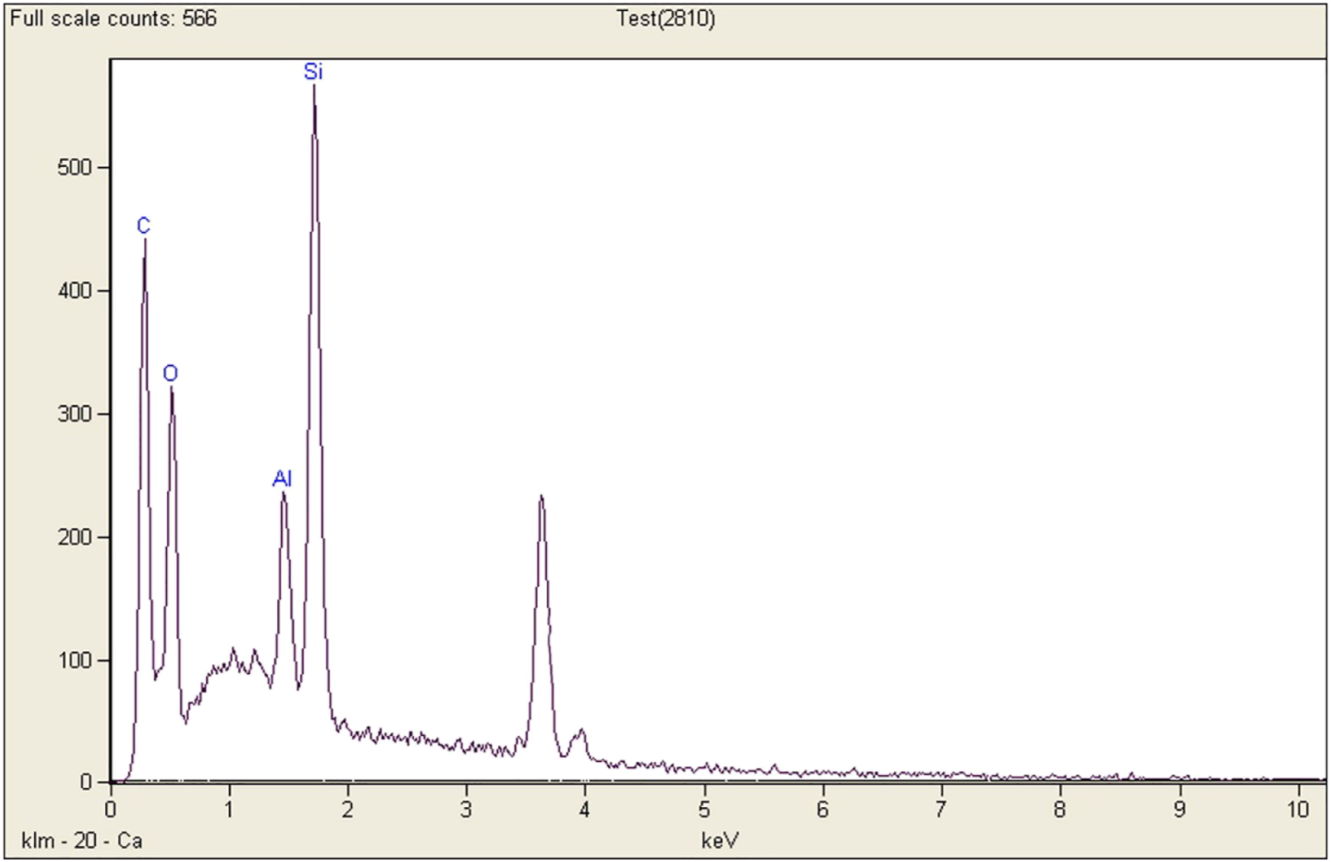
EDX analysis was applied to observe and clarify the chemical composition of the elements as shown in Figure 8, which was received to provide the details of the element percentage in the sample. The EDX pattern of MWCNT includes carbon, oxygen, silicon, and aluminium atoms in which weight percentages (W %) of carbon, oxygen, silicon, and aluminium were 66.74, 18.70, 11.26, and 3.30, respectively. This result clearly illustrated the presence of the dispersing 0.7% of MWCNTs in resin epoxy.
Tensile tests and tensile after impact
The current arrangement of analyses focused on demonstrating the modulus, tensile strength, and toughness subsequent to endeavour six projectile penetrations and of subsequent. Further, they were at the different targets' angles between 0 and 40°. 17 Subsequently, the motivation behind the tensile tests was to decide the conduct of the materials under applied forces.
Figures 5–11 display the post-impacts and the intact specimens, at the various inclined targets with the different volumes of the CNT. Furthermore, X-axis indicates tensile strain (out of 100) and Y-axis indicates tensile stress in megapascal (MPa) in neat epoxy/carbon-Kevlar hybrid fabrics, in post oblique impacts, and all ultimate amounts of stress and strain of tensile strength firmly dropped with increasing the angles of the targets from 0 as a normal impact to 40°. Suddenly, they recently collapsed or slumped specimens already reached to a maximum amount of stress, the decline for the departed commenced in 0 as stress and various levels of the strain. Nevertheless, a sharp rise was observed in the crack initiation. Moreover, formerly initiated across the matrix cracking and the multiple fibre fracture cases as shown in Figure 3 where the interlinear stresses make a considerable contribution. In addition, the post-impact specimens were represented a small and not significant proportion of total tensile stress apply and despite small projected gains compare the intact one. Besides, it is projected that they continue dropping as well. Comparison of stress-strain curves for the ultimate tensile strength values in the neat epoxy specimens Comparison of stress-strain curves for the ultimate tensile strength values in the 0.1% CNT specimens Comparison of stress-strain curves for the ultimate tensile strength values in the 0.3% CNT specimens Comparison of stress-strain curves for the ultimate tensile strength values in the 0.5% CNT specimens. Comparison of stress-strain curves for the ultimate tensile strength values in the 0.7% CNT specimens. Comparison of stress-strain curves for the ultimate tensile strength values in the 1% CNT specimens. Comparison of stress-strain curves for the ultimate tensile strength values in the 1.5% CNT specimens.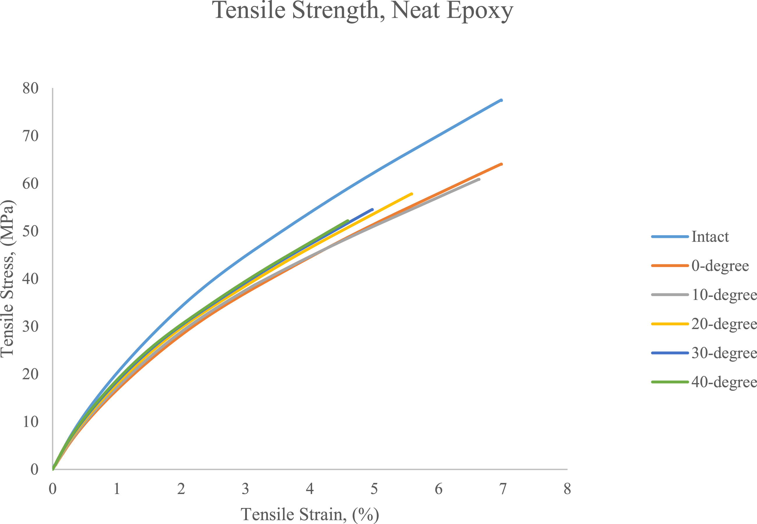


Furthermore, Figure 5 compares changes in the tensile testing experiment distribution among the six various specimens with neat epoxy from zero to about 6.97% strain. The only specimen where the minimum amount of tensile is expected to rise by 77.51 MPa is the intact specimen while 40-degree one is expected to show the highest drop in amount of tension stress over the tensile test. Additionally, all the specimens display the fluctuations by reaching to the tensile strength until cracking. Therefore, it is equally important to indicate from relatively minimum amounts of strain for the post oblique impact specimens from 0.88% to 2.03%. Namely, by rising the inclines the highest variation was about 67%. Besides, for normal post impact specimens, first signs of cracking appear at 64.07 MPa and about 5.3% more than 10-degree impact. Then maximum of strain is 6.89%, about 4% more than 10-degree. In addition, the plot shows in 30 and 40-degree impact samples standing at 4.97% and 4.58% strain, and 54.54 MPa and 52.18 MPa. Furthermore, expecting to reach its steady downturn to lead the points of failure. Likewise, a distinctly remarkable trend was shown in the specimens' data being the region of strain at the ultimate of tensile stress to be seen a rise in all over exploring experiences with tensile testing. Nonetheless, the prediction of a deterioration is looking forward to collapsing.
Figure 6 illustrates 0.1% CNT for the intact and post oblique impact sample from 0% to 82.16% tensile strain and between 0-82.16 MPa for tensile stress. Predominantly, it was seen tensile strength was far greater in the intact sample than in the five post-impact samples via the tension testing. Correspondingly, the tensile stress at the collapse of post impacts followed an adequately similar pattern at the breaking points. Additionally, the general trends, though for the post-impact specimens, were a reduction in the value of tensile stress over the collapsing points. Conversely, the intact sample tested a higher trend, cracking at 82.16 MPa tensile stress and 7.51% strain. Conclusively, they suddenly fluctuated over the breaking points, striking the highest and cracking much less than an intact specimen.
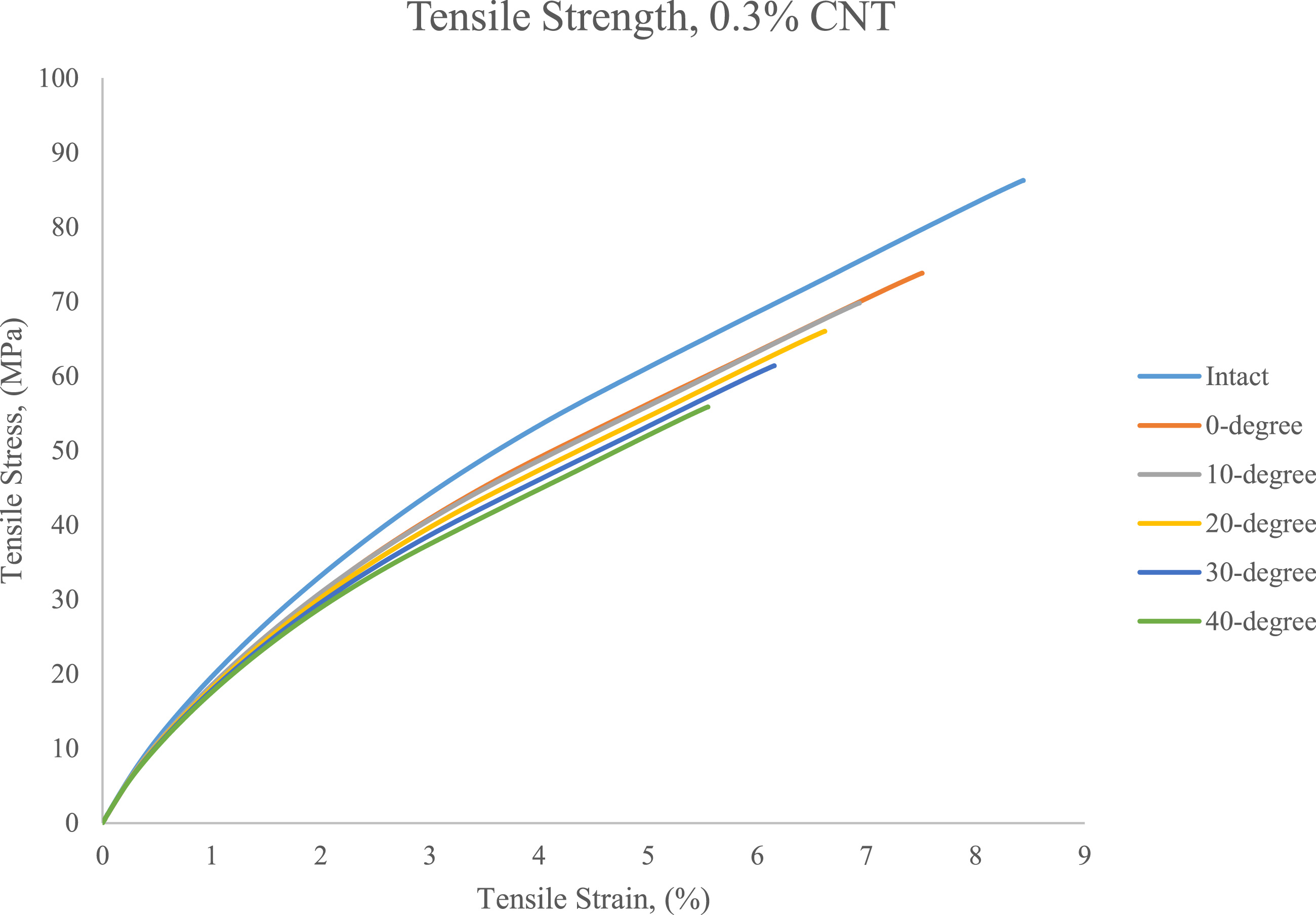
Figure 12 displays the values of stress-strain plots in the compression tensile tests between 5.55-8.44% tensile strains for laminated composite plates reinforced by 0.3%. Overall, the value of tensile stress obtained by tensile developed at first and decreased at the culmination with a stable trend. In addition, by increasing the inclines of the targets in post oblique impact specimens, the value of failure stress gradually dropped from 73.82 MPa to 55.86 MPa and the tensile strain worsened slowly from 7.51% to 5.56%. For the intact one, from zero to about 8.44% strain, the tensile stress’s value boomed to 86.28 MPa. Furthermore, for the intact sample compares with the normal one, the value of the failure tensile stress rapidly downturned from 86.28 MPa to 73.82 MPa, i.e. about 18% higher. At the end of the breaking of all the specimens, the value of tensile stress for the intact one plummeted from 86.28 MPa to 55.86 MPa for the 40-degree one, i.e. 57% higher than post 40-degree one. Ultimately, the plot compares the ultimate value of failure tensile stress was tested for the post-impact specimens is 73.82 MPa although the worst is 55.86, i.e. normal impact one is 34% more than the post 40-degree one. Young’s modulus values of neat and post oblique impact specimens.
Figure 7 shows the tensile testing behaviour of composite laminates reinforced epoxy by 0.5% CNT. Overall, the intact specimen was the dominant type and continues up to the fracture point with 92.64 MPa stress at 8.15% strain. Accordingly, post impact at 40-degree one commands the minimum amount of stress with 60.06 MPa in 5.61% tensile strain. At the same point, on post 30-degree impact specimen rising relatively to 50.23 MPa in 5.68% strain to break, respectively. Moreover, current trend is confirmed to extend constantly with a projected highest tensile stress value of the others. Categorically, 0-degree impact one came in second rank with 77.51 MPa stress and 7.83% tensile strain. In sharp contrast to this, the intact one valued the others at much higher levels.
Figure 8 displays the tensile testing experiments on various composites reinforced by 0.7% CNT; intact and post oblique impact from 55.11 MPa to 95.35 MPa of the tensile strength, and between 6.01-10.59% of tensile strain. Particularly, whereas the value of intact specimens that rose after loading the value of tensile stress and strain of 40-degree impact one decreased over the 77% of strain and the 73% of tensile stress. Furthermore, in 8.83% of the strain, the highest value of the tensile strength with post-impact one was 73.62 MPa, which was evaluated 7% more than 10-degree, 23% more than 10-degree, 20% more than 30-degree one. Therefore, normal impact value was more than the stressed amount of post impact 40-degree one, which reached nearly 34%. However, apart from a brief increase from the initial point to 6.01%, and the amount of tensile strength in the post-impact 20-degree specimen, which continuously increased until collapse at 64.48 MPa. Furthermore, the tensile strength amounts rose until they broke; the intact one at 95.35 MPa, post normal impact at 73.62 MPa, post 10-degree at 68.95 MPa, post 20-degree at 64.48 MPa, post 30-degree at 61.25 MPa, and post 40-degree at 55.11 MPa.
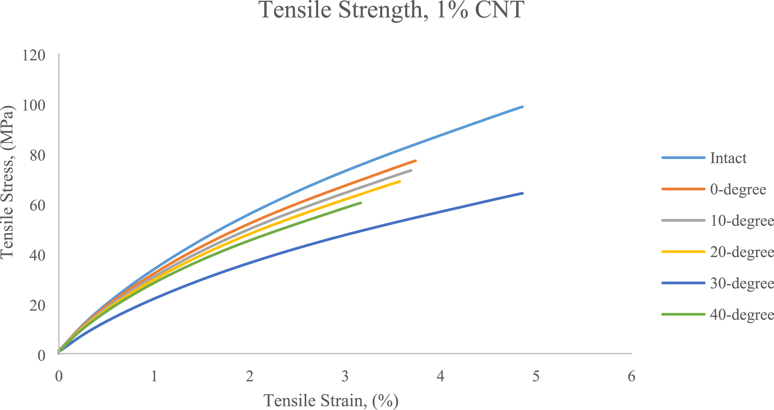
Figure 9 shows the number of stress–strain curves plotted by the tensile testing experiments on epoxy reinforced by 1% CNT. In addition, according to the tensile stress and strain in the intact and post oblique impact specimens, the strain range was between 0- 4.86%. During the tensile experiments, the figure for the specimens steadily increased and reached the highest point for post-normal impact at 76.98, for 10-degree at 73.12, for 20-degree at 68.72, for 30-degree at 64.02, for 40-degree at 60.15, and for the intact at 98.54 MPa tensile stress. The stress slightly decreased from 98.54 to 60.15 MPa before experiencing a dramatic acceleration to the peak of nearly 64% less than an intact specimen value. The value of tensile strain concerning the inclines of targets against the impact between 0 and 4.86% when it initiated with yield points then the fracture initiation at the different points. On the contrary, the amount of stress gradually increased in the intact specimen at 46.28 MPa when that rest of values reasonably decreased stable within the same value. Consequently, the last remarkable feature in the post impact at 30-degree specimen was the value of tensile stress causing by tension stabilised, which was climbing until breaking to a low point of 76.98 MPa until 3.73% strain then it continued to incline steadily until the breaking point. Although the main reason for breaking was indicating lower energy absorption characteristics or brittleness of the specimens, the intact specimen showed the largest amount of tensile stress in relation to the tensile testing.
Figure 10 shows the tensile testing investigation of composite laminates reinforced epoxy by 1.5% CNT. Admittedly, the post-impact specimens were demonstrated a small-scale and not considerable proportion of complete tensile stress utilise and despite small projected achieves compare the intact one; it is calculated they reach falling so. Accordingly, post 40-degree impact commands the minimum amount of tensile stress with 64.66 MPa in 2.26% strain. Therefore, at the same point on post 30-degree impact specimen was relatively rising to 68.79 MPa in 2.34% tensile strain to break. Furthermore, mentioned trends gradually continues with a projected maximum tensile stress value of the others. An additional post normal one came in second with 78.41 MPa tensile stress and 2.44% strain, respectively.
The bar chart in Figure 12 displays the Young’s moduli of tension testing experiments in hybrid fabrics reinforced epoxy by various values of CNT for seven classes of the specimens, including intact one and post-impact ones. According to the inclined target impact and the fraction of the CNT volume, the intact specimens are expected to be the illustrations of the highest ones. Therefore, they undoubtedly show the maximum in each group of the CNT contents. Consequently, in 0.1% CNT specimens, as it was expected the intact one is the maximum, but among the impact ones, normal impact anticipated the highest amount, but the greatest one was the 40-degree impact at 7.75 GPa. The ratio of stress to strain, Young’s modulus, for 1.5% CNT at post 10-degree impact was 35.95 GPa compared to the 0.1% CNT after 10-degree impact. Presently, it means the difference between the highest and the lowest one was about 45%. For 1% CNT, at post 10, 20, 30, and 40-degree impact about 13 GPa and the difference among them was negligible. Correspondingly, the difference between the maximum and the minimum one was about 32%. On the other hand, the lowest Young’s modulus was on the neat epoxy specimens at post 30-degree impact, which was calculated for 7.81 GPa in all the intact specimens. The 0.3% CNT, the range of the Young’s modulus is around 7 GPa the difference among them was negligible. Otherwise, for the neat epoxy CNT, the difference between maximum and minimum of this category is about 24%. Overall, the category of the richest volume of CNT content acquired the maximum level of tensile moduli. However, Young’s moduli after 40-degree impacts were expected to show the minimum, but some of its amounts showed no signs of the decrease were found.
The calculation of properties applying tensile toughness of each specimen illustrated assorted results of tensile strength as well as elongation for them. The tensile toughness of the reinforced composite laminates is presented in Figure 13, which illustrates the tensile toughness values range between 73.28 and 504.72 J.m−3. Theoretically, it was expected the value to be increased within this range with increasing in CNT weight ratio. Practically, the intact specimen with the highest weight percent of 1.5% CNT had the highest tensile toughness at 145.39 J.m−3, while for the maximum inclined post impact with neat epoxy had the least tensile toughness at 119.67 J.m−3. Since the material is under tension, the toughness relatively reflects the property of resisting damage and absorbing energy. The horizontal bar chart in Figure 13 compares some experimental results of the toughness. Moreover, comparisons between the specimens are admitted by owning the various CNT volume, which versus intact and post impact. Plus, it illustrates the specimens possessing of the maximum and the minimum amount of toughness. Additionally, the intact specimen by 1.5% of CNT, as the toughest specimen, strikes at 3688.48 J.m−3. Besides, specimens by 0.1% of CNT compared to the other specimens demonstrates the second toughest specimens collapse because of the toughness amount is between 54.24 and 1026.82 J.m−3. Systematically, 0.7% CNT is third tough one, roughly triple as much as the rich CNT content and doubled more than the normal impact by neat epoxy being the only specimen exposing less energy absorbed by 8.45 J.m−3 than all of them. In addition, in terms of toughness for less volume of CNT by 0.1%, the intact one is the toughest specimens by 1026.82 J.m−3, more than approximately four times of post-normal ballistic impact at 250.15 J.m−3. Comparatively, 0.3% CNT is the third tough material to absorb at 1615.19 J.m-3 by the peak toughness amount of the intact specimen then by raising the angle of impact on the level of toughness dropped to 129.05 J.m−3. Relatively, at 20-degree, 0.5% CNT has over doubled more than neat epoxy, 46% is more than 0.1% CNT, and is closed to the toughness of 0.3% CNT. As for neat epoxy at the post impact, 40-degree is the least value of toughness with 46.75 J.m−3. Furthermore, in the post-40-degree impact, 1.5% CNT shows the maximum amount of the toughness; about more than triple the intact specimen, nearly double the 0.3%. Finally, the maximum value of the toughness is 3688.48 MPa for 1.5% CNT at the intact specimen and the minimum amount is 46.75 MPa for the neat epoxy at 40-degree. Tensile toughness values of neat and post oblique impact specimens.
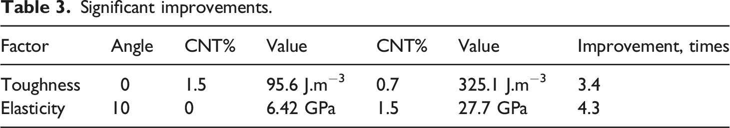
Significant improvements.
Categorically, for the brittle-reinforced composite systems, the increased toughness value in the systems was experimentally attributed to the fibre breakage and pull out, which accompanied generally system crack growth. In the ductile matrix for the composite panels, the low transfer efficiency of tensile toughness of the epoxy resin (with or without CNT) into delamination tensile toughness. An equally important issue was the result of the constraint on the evaluation of an extended area of the curve. Therefore, another problem was in the region of enriched resin between plies by the fabrics in the adjacent plies.
By observing the experimental results, a nonlinear increase in tensile toughness is observed as the CNTs weight fraction rises from 0.1% to 1.5%, which this result is in harmony with Bochnia et al. 25 The experimental results are also dependent on the availability of the CNTs with controlled shape and size. 3 For instance, the diameters and the lengths and of all CNTs are not equal to each other in the fabricated specimens. Similarly, as Ahmed et al. 33 discussed, the CNTs do not have the same waviness factors. Another reason for the observed nonlinear behaviour in the experimental results may be explicable in terms of some lattice defects within the CNTs’ particles in the various specimens of the CNTs-reinforced matrix composites. These results are in line with Habibi et al. 50 Moreover, these results can be some sources of the nonlinear behaviour of the tensile toughness and other mechanical properties including the yield strength and the ultimate tensile strength of the specimens that are harmonious with related literature. 25 Comprehensively, these experimental results may be used to explain the relatively proper correlation between impacted specimens and the amount of tensile toughness.
Conclusion
The aim of this experimental study was explicable in terms of assessing the effects of tensile testing on two different types of specimens. The first type of the specimens were impacted ballistically, whereas the second type of specimens were not impacted, i.e. they were intact. The results of the study showed that the intact types reacted totally different from the impacted types. Moreover, the findings of this research provided extra insights into an optimum approach that by increasing the amount of CNTs into the resin epoxy systems the tensile strength values may improve, too. One of the more significant findings to emerge from this study was that the incorporation of CNTs, for the intact specimens, increased the Young’s modulus value by up to 36 GPa. However, the tensile toughness value dropped by up to 145 J.m−3. Concisely, the experimental findings of the study provided new insights into tensile after oblique impact. Furthermore, results from this study indicated that 0.7% CNTs showed maximum tensile toughness values and the highest values of Young modulus were followed by tensile strength at 1.5% CNTs. In addition, the findings of this research provided a vision that relatively limited specimens size may offer better application of materials in advanced manufacturing and space industries. Therefore, it will be interesting to address all the concerns raised in the forthcoming investigations on utilising the potentials of CNTs in polymer composites. Finally, the study provided a number of important implications for the future research including techniques of inclusion of CNTs into the epoxy resin, which may help the researchers to establish a greater degree of accuracy on this area of research.
Footnotes
Acknowledgements
The authors would like to thank the Ministry of Higher Education, Malaysia for funding the research and the support from the Department of Aerospace Engineering, Universiti Putra Malaysia.
Declaration of conflicting interests
The author(s) declared no potential conflicts of interest with respect to the research, authorship, and/or publication of this article.
Funding
The author(s) disclosed receipt of the following financial support for the research, authorship, and/or publication of this article: This work was funded by the Ministry of Higher Education under the Fundamental Research Grant Scheme with Grant No. FRGS/1/2019/STG07/UPM/02/10.