
Abstract
Three dimensional (3-D) braided composite is one element of the structures which must connect with other structural elements, to form load transmission path during its service in aerospace, transport and engineering structures. Bolted joints are usually the lower-cost option because of its simplicity, low-cost tooling, and inspection requirements. Secondary bending induced by minor eccentricity of the loads occurs in many types of joints and can cause serious problems. In this study, flexural performance of 3-D braided open-hole composite (3DBOHC) considering open-hole diameter and preform size is systematically studied. Three-point bending test combined with a high-speed camera observation was conducted. The results show that the damage initiates in the top surface of 3DBOHC. Failure mode gradually changed from fiber breakage into interface debonding, when increasing the braiding angle. The reduction of composite strength becomes less sensitive to drilling process when braiding angle increased. The strength reduction of 3DBOHC with hole diameter of 1.5 is 13.8%, 10.3% and 5.8% for 10°, 20° and 30°, respectively. The increase in modulus and strength achieved by increasing preform size is higher for larger braiding angle 3DBOHCs. When the preform size increased from 3 ⅹ 9 to 3 ⅹ 17, the modulus increase for 10°20°and 30° 3DBOHCs is 25.4%, 42.5% and 43.2%, respectively. The strength increase for 10°20°and 30°3DBOHCs is 20.3%, 26.3% and 30.2%, respectively. This research provides a comprehensive insight for the design and application of 3-D braided composite joints.
Introduction
Three-dimensional (3-D) braided carbon fiber reinforced resin composites have been widely used in aerospace, aircraft and transport industries 1 due to its high strength-to-weight ratio, excellent delamination-resistance and high impact tolerance. 2 For the commercial viability of products/structures, joining operation is required to assemble the individual braided composites and other parts into the intricate final product. The joining of components is generally accomplished by adhesive joining, mechanical joining and fusion joining processes. The mechanical joining provides adequate strength by using mechanical fasteners like rivets, bolts, screws, etc. However, the drilling process in elements is required before their mechanical joining. Joints and connections are perceived as the weakest links in the structures and they often turn out to be the initiators of structural collapse. 3 The optimization of all the drilling parameters including opening diameter and preform size is required otherwise, it leads to various types of defects during the mechanical joining of braided composites.4,5
The strength of mechanical joint is a function of fastener loading, fastener fit tolerance, clamping area, geometry size and bolt diameter, etc.6,7
Bolt diameter and geometry size are two of the most import parameters in determination of joint strength. The failure load of bolt increases, with increase in the bolt diameter. However, the available width of composite decreases due to the increased bolt diameter, which declined the bearing capacity of composite joint. 8 Sun et al. 9 investigated the effects of notch size on the tensile properties of laminates. When the notch size increased from 0 to 18 mm, the tensile strength showed 69% reduction. Hu et al. 10 found that the notched composite strength is 60% of the unnotched composite. The stiffness of composite was found to be decreasing with increasing the hole size. 11 Wu and Lai 12 investigated the failure strain of open-hole composite under tensile load. The failure strain decreased from 24% to 7.9% with increasing the hole size. The strength of open-hole composite is sensitive to its geometry size. Bian et al. 13 found the compressive strength of the WTDR-6 (width-to-diameter ratio is 6) open-hole plate is larger than that of the WTDR-4 open-hole plate. The carbon/carbon composite plate is insensitive to the opening hole when the WTDR exceeds 6. Li et al. 14 found that the average load declined gradually from 12655 N to 12608.5 N, when width to bolt diameter ratio changed from 5 to 7. The average load declined gradually from 12626.5 N to 12615.5 N when edge distance to diameter ratio (e/D) changed from 3 to 3.33. A clear increase in offset bearing strength was observed as the e/D ratio increases. 15
The cracks and deformation of composite is more obvious with bigger open holes. 16 Laminates present various deformation and failure modes. The failure of laminated composites initiated at the stress concentration region, 17 especially at the edge of the hole. Then it propagated to the two sides of matrix 18 or fiber 19 depending on the load direction. The cracks not only propagated along the fiber direction, but also propagated along the transverse direction. 20 As the hole size increased, the main failure mode of woven composite changed from fiber pull-out to fiber breakage. 21 Damage evolution changes with varying composite size. With the increase of the width to thickness ratio, the joint becomes more prone to deformation under the same condition. When the width to thickness ratio reaches 50, the joint fails in advance due to poor load-resistance. 22 With the increase of width to bolt diameter ratio, the failure mode of the joint gradually changes from net tension to extrusion. 14 The shear-out failure mode was dominant with low e/D ratios. The bearing failure mode was observed for specimens with larger e/D ratios. 15 Braided composite possesses a very special structure in which all the yarns interact with each other. The interlaced braided structure can effectively block the cracks23,24 and makes stress distribution as well as damage evolution around the open holes. 25 The stress concentration around the open holes results in the damage modes of composites different from the unperforated composites. Hence the mechanical behavior of braided composite structures is considered critical in joints design, but it is unclear yet. A study upon this issue is urgently needed.
Mechanical performance of composites shows significant differences after the open-hole is introduced. 3-D braided composites have demonstrated superior notch insensitivity than laminated composites. 19 When used as joint parts, various types of loads are applied to braided composites in practical. Primary bending load can be avoided by keeping the loading as close as possible to collinear. However, secondary bending induced by minor eccentricity of the loads occurs in many types of joints and can cause serious problems. 26 Kabche presented an investigation of the structural performance of hybrid composite-to-metal bolted joints under flexural load. The joint using a short plate, a foam insert and a single row of bolts was found at least 33% stronger and 29% stiffer compared to a standard bolted joint. 27 Ben et al. 22 presented a comprehensive numerical and theoretical investigation on the flexural capacities of composite joints. The results showed that the yield bending moment and the plastic bending moment decreased, when width-to-thickness ratio of composite increased. Haeger et al. 28 presented a detailed investigation of the open hole bending fatigue behavior of carbon fiber reinforced plastic under consideration of drilling-induced damage. A negative impact of drilling defects on lifetime of composite was found in the early stage of fatigue. Multi-layer failure occurs at high loading while delamination is the characteristic failure mode at low loading. Gupta et al. 29 evaluated the flexural behavior of open-hole laminates with varying stacking sequences. The tensile and compressive failure was observed during three-point bending test. The damage mode of laminates becomes more complex with introduction of open holes due to the variation in stress distribution. Textile structures significantly influence the mechanical behavior of fiber reinforced composites.30,31 Braided composite exhibits particular damage evolution mechanism under flexural load due to its excellent structural integrity. 32 Liu et al. 33 studied the failure mechanism of 3D braided composite under flexural loading. The tensile cracks can be arrested by the heterogeneous microstructure. The ultimate failure under flexural loading was resulted from the multiple cracking in compression. Singh et al. 34 investigated flexural property of braided composite with braiding angle of 30°, 45°and 60°. Localized crushing decreased significantly with increasing braiding angle. Hu et al. 35 studied the bending properties of 3D five directional braided composite considering the difference of yarns configuration in corner, surface and interior unit cells. The damage areas in surface unit cell and corner RUC were much bigger than that in the interior RUC. More damage was observed on the top zone than the bottom zone in all the three RUC regions. A conclusion can be draw from above literatures that the flexural behavior of 3D braided composite is significantly influenced by the braided structure.
Braiding structures with different braiding angles are designed for composites to satisfy the strength requirement of composite joints and can significantly influence the flexural property of braided composite. The flexural performance of composite is obviously affected by the introduction of open holes. Chamis investigated damage initiation and progressive fracture of composite joints under various loading conditions. The results show that flexural loading is detrimental to damage tolerance characteristics of composite joints. 36 The response of the open-hole braided composite with different braiding angles under flexural load is vital in braided composite joint design and it has not been explored yet. The related research is urgently needed. In addition, different preform sizes are used to satisfy the strength requirement. Hence, a study to investigate the flexural performance of 3DBOHCs with various preform sizes, hole diameters and braid angles was conducted for their appropriate selection in engineering design of braided composite joints, which can retain the structural performance instead of potentially compromising the whole system. Three-point bending test of 3DBOHCs was conducted. A high-speed camera system was used to capture the damage process information. Flexural response of open-hole braided composite with different hole diameter, preform size and braiding angle were thoroughly discussed. This study can provide a comprehensive insight for design and application of 3-D open-hole braided composite.
Experiment
Preparation of 3-D braided open-hole composite
Mechanical property of carbon fiber.

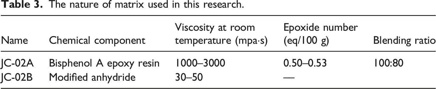
Mechanical property of epoxy resin.

Figure 1 presents the manufacturing process of 3D braided composite. 3-D braided preforms were fabricated in a four-step 1 ⅹ 1 braided machine. Braided yarns were fixed to the carriers on the machine basis. The carriers moved in the basis plane along row and column direction alternatively during four-step braiding process. The yarns interlaced with each other during the movement. The carriers returned to the initial arrangement after four-step movements. The oblique angle between braided yarns and the longitudinal axial is called “braiding angle.” Different braiding angles were realized by adjusting the beating-up force. Different braided preform sizes were fabricated by changing the number of braided yarns in row and column. 3D braided preform was impregnated with resin by vacuum assisted resin transfer molding (VARTM) technique. The pressure of pump was −0.1 MPa during VARTM process. Manufacturing process of 3-D braided composite.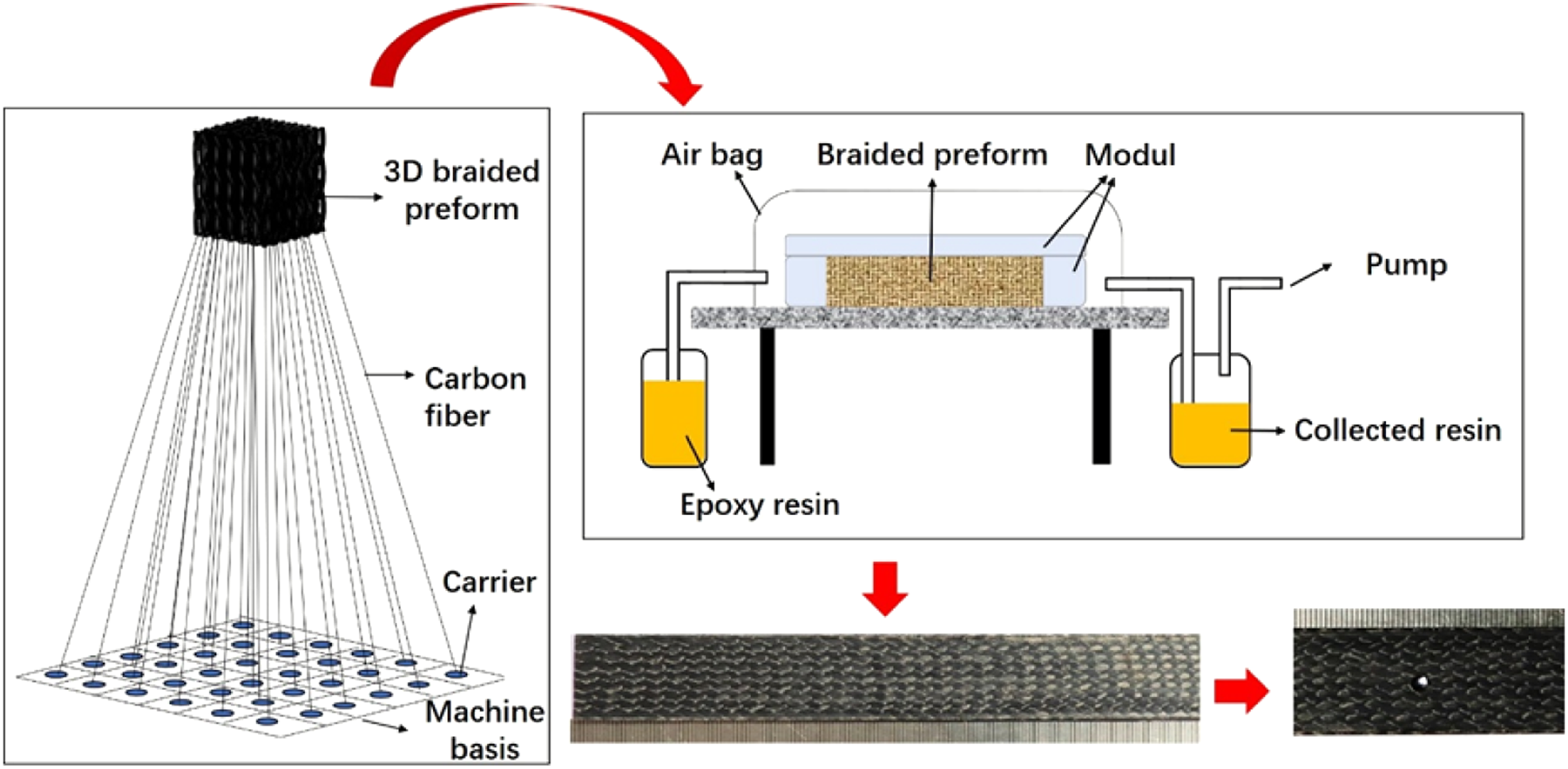
The nature of matrix used in this research.
Fiber volume fraction for each sample.

Figure 2 shows the braided parameters used in this research. The larger the braiding angle, the higher the beating-up force. The high beating-up force generates more serious yarn damage due to the large frictional force between the fibers and beating-up facility. This can weaken the mechanical performance of composites and cause more uncertainty of experimental results. Thus, the maximum braiding angle in our research is 30°. We selected three braiding angles with equal interval (10°, 20° and 30°) to reveal the effect of braiding angle on mechanical performance of 3D open-hole braided composite. Braided preforms with braiding angle of 10°, 20° and 30° were presented in Figure 2(a). Different preform sizes with row and column yarn number of 3 ⅹ 9, 3 ⅹ 13 and 3 ⅹ 17 were fabricated as shown in Figure 2(b). 3-D braided preform with different (a) braiding angles and (b) preform size.
Composites were cut into test samples according to GB/T 1449-2005. The length of sample is 20 times than the thickness. 3DBOHC samples were manufactured by drilling a circular hole in the centroid of composites. Holes with diameters of 1.5 mm, 3 mm and 6 mm were drilled. Figure 3 shows 3DBOHC samples with different diameters holes. Figure 4 presents 3DBOHC samples with different yarn numbers in column and row as well as braiding angles. 3DBOHC samples with different diameters holes: (a) 0 mm, (b) 1.5 mm, (c) 3 mm, (d) 6 mm. 3DBOHC samples with different preform size and braiding angles: (a) 3ⅹ9, 10°, (b) 3ⅹ9, 20°, (c) 3ⅹ9, 30°, (d) 3ⅹ13, 10°, (e) 3ⅹ13, 20°, (f) 3ⅹ13, 30°, (g) 3ⅹ17, 10°, (h) 3ⅹ17, 20°, (i) 3ⅹ17, 30°.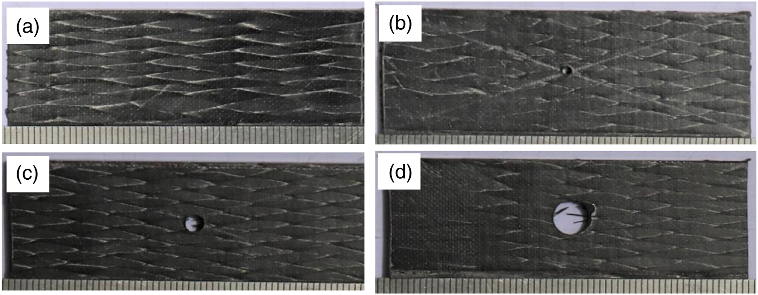

Three-point bending test
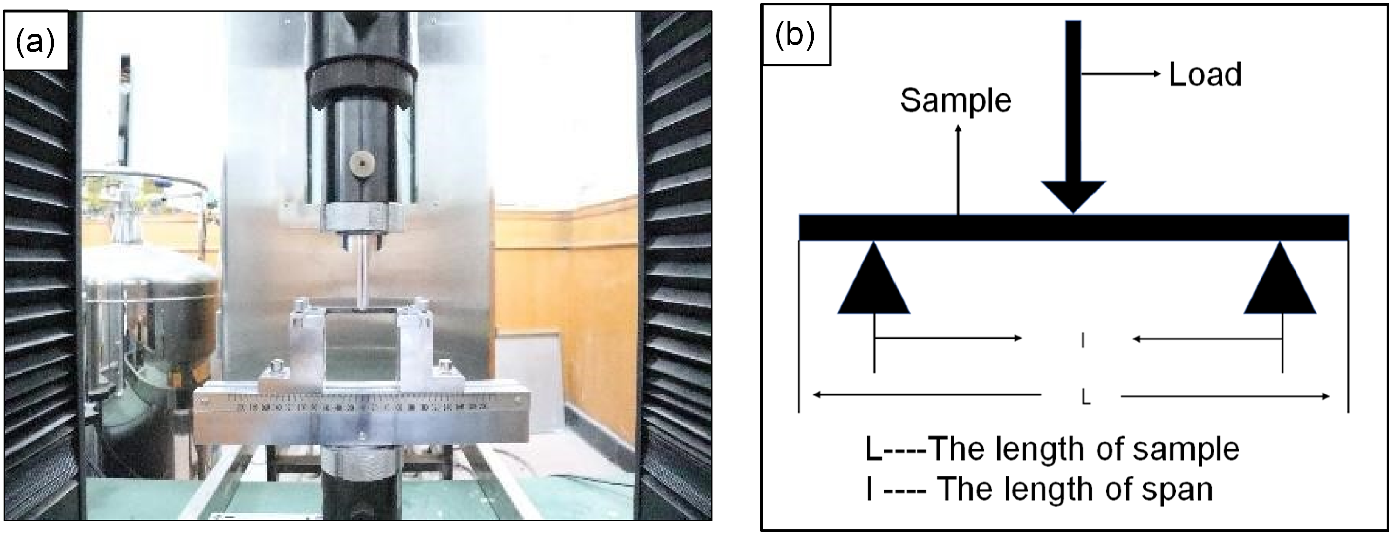
Three-point bending test was conducted on a universal testing machine. The universal testing machine was supplied by Shenzhen Sun Technology Co., Ltd, China. The model is CMT6000. Figure 5 presents the setup of bending test. 3DBOHC samples were fixed between two sporting rollers and pressure punch. According to GB/T 1449-2005, the span between two sporting rollers is 16 times the width of 3DBOHC samples. The loading rate was 2 mm/min. The load and deflection of 3DBOHC were detected by the sensor. The flexural strength and modulus were calculated by equations (1) and (2), respectively. Three-point bending test apparatus: (a) Test machine, (b) Schematic diagram of loading device.

Characterization of failure mechanisms
A high-speed camera system (IX Camera Ltd, United Kingdom) was used during three-point bending test to capture damage initiation and development of 3DBOHC. The high-speed camera system was triggered synchronously with the three-point bending machine. The frequency of high-speed camera photography is 2000 fps. Observation of damage morphology was conducted with a 3-D microscopic system (VHX-5000, Keyence, Japan).
Result and discussion
Damage process of 3-D braided open-hole composites was characterized with the high-speed camera system. The flexural property of 3DBOHC with different hole diameters, preform sizes and braiding angle was investigated.
Damage initiation
Figure 6 presents typical damage process of 3DBOHC under three-point bending load. The arrow in Figure 6 points out the damage initiation of 3DBOHC. In the case of three-point bending load, composites undertake compressive load in the top surface and tensile load in the bottom surface.
37
The pictures obtained from high-speed camera demonstrated that the crack initiates in the compressive-loaded surface at 40 s. The crack enlarged at 60 s. No damage was observed in the bottom surface. This is accordant with the results found by Gholizadeh et al.
38
This is attributed to the excellent tensile property but poor compressive load-bearing capacity of carbon fibers. During the flexural deformation, the fibers in bottom surface can withstand tensile load and prevent the damage initiating. However, due to the inferior compressive strength of yarns and resin, crack initiates in the top surface under compressive load and then extends outwards. Damage process of 3DBOHC under three-point bending load: (a) 0 s, (b) 40 s, (c) 60 s. (The arrow in figure points out the damage initiation of 3DBOHC).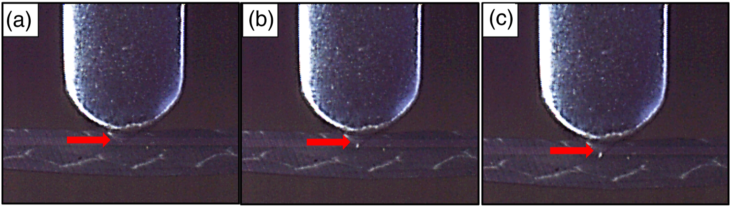
Different open hole sizes of braided composites are required to assemble the components through mechanical fasteners. Circular holes with varied diameters (1.5 mm, 3 mm and 6 mm) were perforated in the centroid of composite. Figure 7 shows the load-displacement curve of 3DBOHC with different braiding angles and hole diameters. The load increases steadily first. After exceeding the peak load, it decreased in a zigzag pattern. When the stress exceeds the ultimate strength, the interlaced yarns progressively fractured. A time interval exists between the breakage of two adjacent yarns. When the crack propagates to the yarn, the superior load-carrying capacity of braided yarns blocks the crack, rising the load on composite until the yarn breakage. After that, the load declines until the crack extends to the next braided yarn. This failure process generates a zigzag-pattern decreasing curve of composite. Load-displacement curve of 3DBOHC with different hole diameters and braiding angles.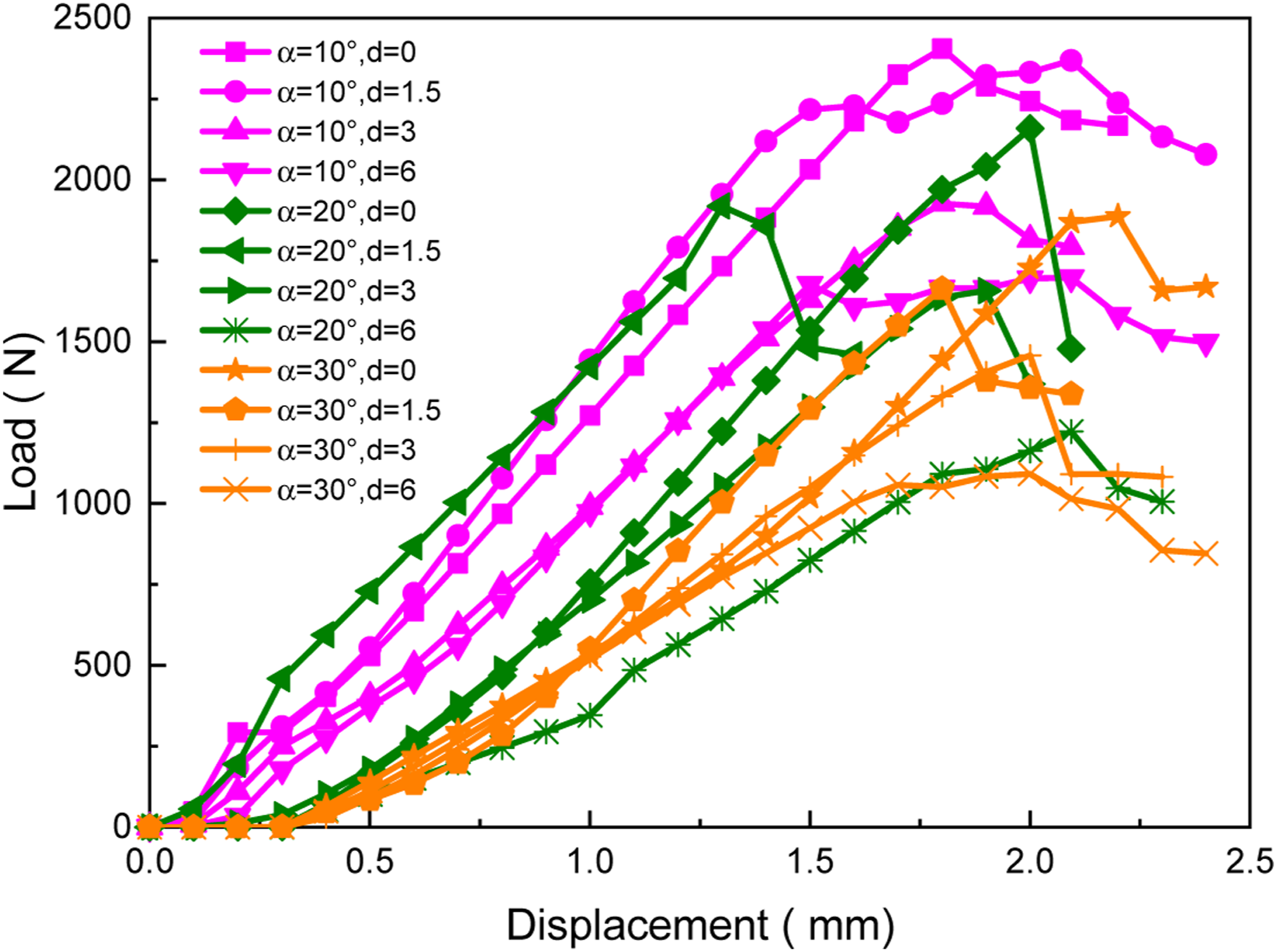
3DBOHCs present varied load-bearing capacity under three-point bending load. Figure 8 presents the flexural modulus of 3DBOHC with different hole diameters and braiding angles. It can be seen from Figure 8(a) that flexural modulus decreased with introducing the open hole. The larger the hole diameter, the smaller the flexural modulus. Flexural modulus of 3DBOHC decreased with increasing braiding angle. This is due to the increase in inclination angle of braided yarns by increase of braiding angle. This results in declining mechanical performance of carbon fibers along the axial direction. The braided composite is more prone to deformation under three-point bending load. Thus, the modulus decreases by increasing the braiding angle. However, the decreasing rate is different. As shown in Figure 8(b), the decreasing rate of flexural modulus slowed down when the braiding angle exceeds 20°. This is due to the changed failure mode of 3DBOHCs. As braiding angle increased, the failure mode gradually transformed from fiber breakage to interface debonding. As the braiding angle exceeds 20°, the debonding of interface dominates the failure process (discussed in failure mode section). The fibers play less role in the determination of flexural modulus at higher braiding angle. Thus, the dependence in braiding angle in determining the flexural modulus weakened. The decrease rate of flexure modulus slowed down. Flexural modulus of 3DBOHC with different hole diameters and braiding angles. (a) Bar graph, (b) Line graph.
Figure 9 shows the flexural strength of 3DBOHC with different hole diameters and braiding angles. Figure 9(a) presents the bar graph of flexural strength for 3DBOHCs. When the hole diameter is 1.5 mm, the flexural strength decreased from 1013.5 MPa at 10° to 745.4 MPa at 20° and 620.0 MPa at 30°. Flexural strength presents similar decreasing trend at diameter of 3 mm and 6 mm, as when the braiding angle increased. This is also due to the declined mechanical performance of carbon fibers along the axial direction of composite as increasing the braiding angle. The drilling process concentrates the stress around the hole edge. However, it didn’t change the variation trend of flexural strength when braiding angle changed at current parameters. It can also be found in Figure 9(a) that the flexural strength obviously decreased with increasing the hole diameter. But the sensitivity of strength reduction to the drilling process at different braiding angle samples is different. For example, the strength reduction of 3DBOHC with hole diameter of 1.5 is 13.8%, 10.3% and 5.8% for 10°, 20°and 30°, respectively. The reduction of composite strength becomes less sensitive to drilling process when braiding angle increased. This is also due to the gradual transformation in failure mode from fiber breakage to interface debonding as braiding angle increased. The influence of fibers damage due to drilling process on flexural strength of 3DBOHC lessened at higher braiding angles. This can provide important guidance in braided composite joint design. Notably, the reduction of flexural strength accelerated when the hole diameter linearly increases. Figure 9(b) presents the strength reduction ( Flexural strength of 3DBOHC with different hole diameters and braiding angles: (a) Bar graph of flexural strength, (b) Strength Reduction 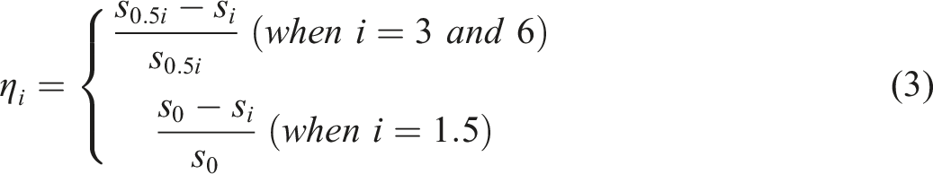

Different perform size and braiding angle
Braided composite with row and column yarn number of 3×9, 3×13 and 3×17 was drilled with the same hole diameter (3 mm). Figure 10 shows load-displacement curves of 3DBOHC with different preform size and braiding angle. Load-displacement curve of 3DBOHC with different preform size and braiding angles.
At the same braiding angle, 3DBOHC shows higher peak load when increases the preform size. The flexural load of 3DBOHC increases linearly with the displacement at first. Then it decreased non-linearly after the peak load due to gradual breakage of the fibers. 3DBOHCs show obviously different load-bearing capacity with changed preform size. Figures 11 and 12 shows flexural strength and modulus of 3DBOHCs, respectively. At the same braiding angle, the flexural strength and modulus of 3DBOHC obviously increases with increasing preform size. We established the geometry model of braided preforms based on the real trajectory of braided yarns. Flexural strength of 3DBOHC with different preform size and braiding angle: (a) Bar graph, (b) Line graph. Flexural modulus of 3DBOHC with different preform size and braiding angle: (a) Bar graph, (b) Line graph.

Figure 13 presents typical direction-turning of one braided yarn in different preform sizes. The increased yarns in row direction enlarged the width of the braided preform, which decreased the direction-turning points of braided yarns as show in Figure 13. Within the preforms with length of 20 mm, there are two obvious direction-turning points for 3ⅹ9 preform, two minor direction-turning points for 3ⅹ13 preform and no direction-turning point for 3ⅹ17 preform. The stress transmission in braided yarns is interrupted at the direction-turning points,
23
this leads to the arise in stress on braided yarns before and around the direction-turning point. The local stress distribution in yarns can accelerates its damage and failure process. The more the direction-turning points in braided yarn, the lower is its strength and modulus. Thus, the flexural strength and modulus increased with increased preform size. Typical direction-turning of braided yarns in different preform sizes.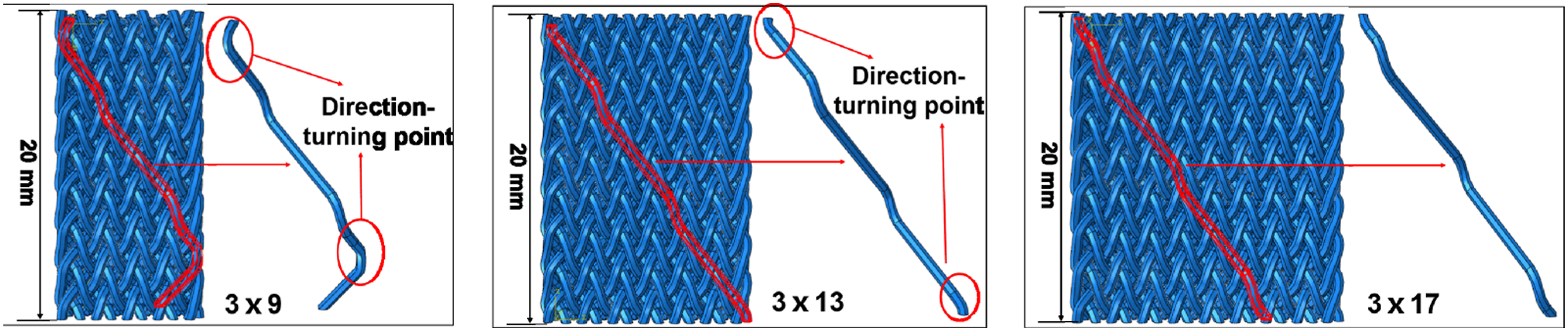
It can also be found in Figures 11 and 12 that the flexural strength and modulus decreased with increasing braiding angle. However, the decrease rate slowed down at higher braiding angle. Figure 11(b) shows the changing tendency of flexural strength. When the braiding angle increases from 10° to 20°, the flexure strength of 3×9, 3×13 and 3×17 samples decreased by 21.3%, 21.2% and 22.8%, respectively. When the braiding angle increased from 20° to 30°, the flexure strength of 3×9, 3×13 and 3×17 samples decrease by 11%, 9.6% and 7.5%, respectively. The decreased gradient slowed when braiding angle linearly increased from 10° to 30°. The flexural modulus presents similar changing tendence as shown in Figure 12(b). This is due to the changed failure mode of 3DBOHCs. As braiding angle increased, the failure mode gradually transformed from fiber breakage to interface debonding as mentioned above. Thus, the dependency of flexure strength and modulus on braiding angle became less sensitive. The decrease rate of flexure strength and modulus slowed down.
Figure 14 presents the flexural modulus and strength increment of 3DBOHCs when the preform size increased from 3×9 to 3×17. When the preform size increased from 3ⅹ9 to 3ⅹ17, the modulus rise for 10°, 20° and 30° is 25.4%, 42.5% and 43.2%, respectively. The strength rise for 10°, 20° and 30° is 20.3%, 26.3% and 30.2%, respectively. By increasing the preform size, the increase in modulus and strength is higher for larger braiding angle 3DBOHCs. This is because the braided structure is tighter in higher braiding angle preforms. More interlaced points exist in the preform with higher braiding angle, which efficiently restrain the movement of braided yarns under bending load. In practical situations such kind of 3DBOHCs with higher braiding angle preform could be very favorable due to their increased flexural modulus and strength. Flexural strength and modulus increment at different braiding angles when the preform size increased from 3×9 to 3×17.
Failure modes
Figure 15 presents the damage morphology of 3DBOHCs under different braiding angles. For 3DBOHC with 10° braiding angle, the braided yarns deflected small angle to the longitudinal axial. When damage occurs in the top surface under bending load, the crack cuts off the yarns to continue its transverse propagation. Thus, the main damage mode for 10° sample is fiber breakage. For 3DBOHC with 30° braiding angle, the yarns inclined at larger angle to the longitudinal direction. When the cracks reach the braided yarns, it deviates around and debond the interface to continue its propagation. The damage mode changes to interface debonding for 30° 3DBOHC. For 3DBOHC with braiding angle of 20°, both the fiber breakage and interface debonding occurred. So, we can say that 3DBOHCs show varied damage patterns with different braiding angles. This demonstrates the mechanism of flexural strength variation at different braiding angles. For 3DBOHC with smaller braiding angle, these are the braided yarns which resist the crack propagation; for 3DBOHCs with higher braiding angle, the crack propagates between the fiber bundles. It is the poor mechanical interface adhesion which resists the extension of crack. Thus, the higher the braiding angle, the lower the flexural strength of 3DBOHC. Figure 16 shows the damage morphology of 3DBOHCs with different preform size. The damage mode of 3DBOHC is similar at varied preform size. Figure 17 presents the damage morphology of 3DBOHCs with different hole diameters. The 3DBOHCs show almost the same damage pattern at different hole diameters. It depicts that at current parameters, change in preform size and/or hole diameter has no significant effect on failure modes of 3DBOHCs. Damage morphology of 3DBOHC with different braiding angle: (a) 10°, (a’) Local magnification of (a), (b) 20°, (b’) Local magnification of (b), (c) 30°, (c’) Local magnification of (c). Damage morphology of 3DBOHC with different preform size: (a) 3×9, (b) 3×13, (c) 3×17. Damage morphology of 3DBOHC with different hole size: (a) 0 mm, (b) 1.5 mm, (c) 3 mm, (d) 6 mm.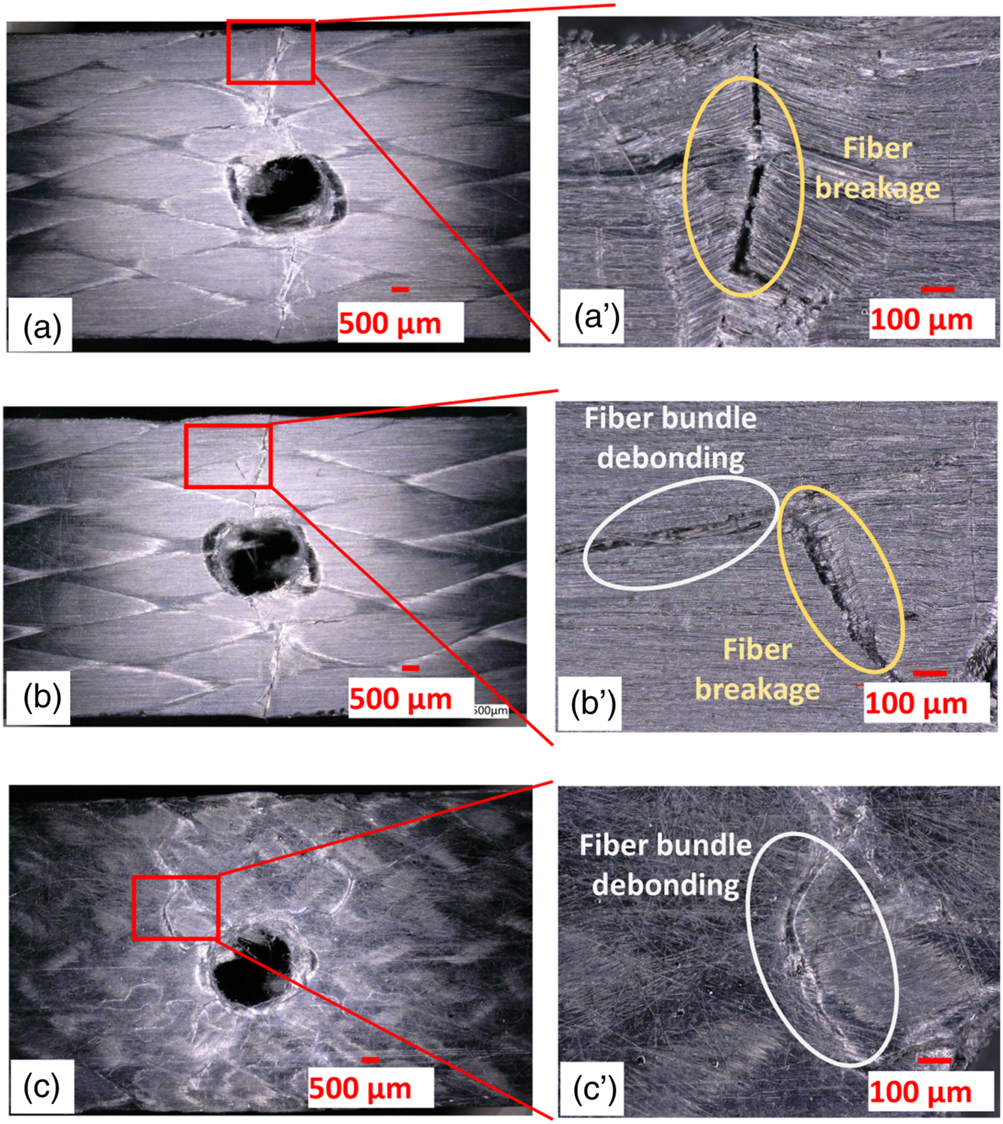


Figure 18 shows the damage morphology of 3DBOHCs in the bottom surface. The bottom surface didn’t show damage initiation. This is attributed to different mechanical performance of carbon fiber under tensile and compressive load. Carbon fiber exhibits excellent performance under tensile load but poor behavior under compressive load. During three-point bending test, the carbon fibers in bottom surface experience tensile deformation while the top surface go through compressive deformation. The top surface was fractured due to the inferior compressive property of carbon fiber. The bottom surface can withstand the tensile load due to the excellent tensile mechanical property of carbon fiber; hence, no damage occurred. Damage morphology of 3DBOHC in bottom surface: (a) 1.5 mm, (b) 3 mm, (c) 6 mm.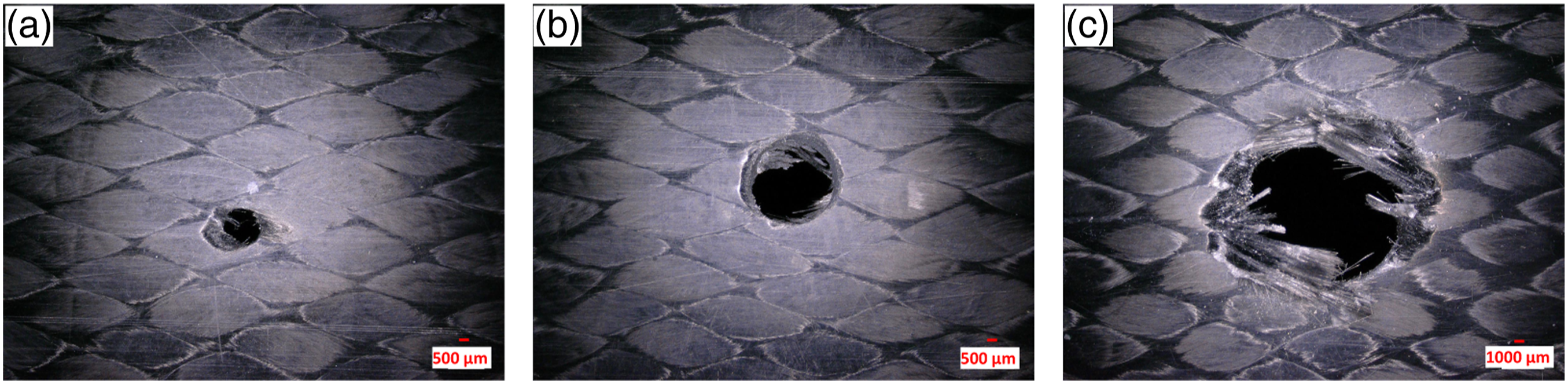
Energy absorption
Energy absorption capacity of materials is an import parameter in structural designs.
39
Specific energy absorption (SEA) of 3DBOHCs has been showed in Figure 19. The specific energy absorption of 3DBOHCs increases with increasing the preform size and decreasing braiding angle as shown in Figure 19(a). This is consistent with the strength changing trend of 3DBOHCs with different braiding angles and preform sizes. Specific energy absorption of 3×13, 10° sample is higher than that of 3×17, 20° sample. This indicates that decreasing braiding angle can compensate the SEA reduction of 3DBOHC due to the decreasing of preform size. The SEA of 3DBOHCs decreases with increasing the hole diameter and braiding angle as shown in Figure 19(b). This is also accordant with the strength changing trend of 3DBOHCs with different hole diameters and braiding angles. The SEA of 10°, 3 mm sample is larger than that of 20°, 1.5 mm sample. This indicates that decreasing braiding angle can also effectively compensate the reduction of SEA due to the enlarging of hole diameter. This can provide useful insight when braiding angle and hole diameter has to be determined in braided composite joint design. Specific energy absorption of 3DBOHC with (a) different preform size/braiding angles and (b) different hole diameters/braiding angles.
Conclusions
The effect of hole diameter, preform size and braiding angle on flexural property of 3DBOHC was investigated in this research. 3DBOHCs with different braiding angles, hole diameter and preform size were prepared. Three-point bending test of 3DBOHCs was conducted. A high-speed camera system was used to capture the damage process information. Flexural response of open-hole braided composite with different hole diameter, preform size and braiding angle was systematically discussed. The main conclusions are as follows. 1. With current parameters, although drilling process changes stress distribution in composite, 3DBOHC shows similar strength variation trend with non-perforated composite as braiding angle increases. The reduction of composite strength becomes less sensitive to drilling process when braiding angle increased. The strength reduction of 3DBOHC with hole diameter of 1.5 is 13.8%, 10.3% and 5.8% for 10°, 20°and 30°, respectively. The flexural strength acceleratively decreases when the hole diameter increases linearly. 2. When the length of the specimen is fixed, the increase in preform width promotes the increasement of flexural strength. The modulus and strength increasement achieved by increasing preform size is higher for larger braiding angle 3DBOHCs. When the preform size increased from 3ⅹ9 to 3ⅹ17, the modulus rise for 10°, 20°and 30° is 25.4%, 42.5% and 43.2%, respectively. The strength rise for 10°, 20°and 30°is 20.3%, 26.3% and 30.2%, respectively. 3. The damage initiates in the top surface of 3DBOHC and then extends outwards. The failure mode of 3DBOHC gradually transformed from fiber breakage to interface debonding when braiding angle increases from 10° to 30. At current parameters, neither increasing preform size nor hole diameter have significant effect on failure modes.
Footnotes
Declaration of conflicting interests
The author(s) declared no potential conflicts of interest with respect to the research, authorship, and/or publication of this article.
Funding
The author(s) disclosed receipt of the following financial support for the research, authorship, and/or publication of this article: This work was supported by the Natural Science basic Research Program of Shaanxi Province (grant numbers 2021JQ-659, 2020JQ-819); Research Fund for the Doctoral Program of Xi’an Polytechnic University (grant numbers 107020527), National Natural Science Foundation of China (grant number 12102144, 12002248); The Jiaxing Public Welfare Technology Application Research Project (grant number 2021AD10012); The Open Project Program of Key Laboratory of Yarn Materials Forming and Composite Processing Technology of Zhejiang Province (grant number MTC2021-04, MTC2020-22).