
Abstract
Thanks to the 2D braiding manufacturing method, the hybrid braided composite composed of the biaxial and unidirectional layers is available in a mass-production manner. For enhancing the crashworthiness of braided composite tubes, the damage characteristics and energy absorption capacity of braided composite with biaxial/unidirectional hybridization structures under axial compression were studied in this work. The axial compression tests were conducted on pure biaxial and unidirectional braided tubes (BBB and UUU), and hybrid tubes with different surface and inner layers (BUB and UBU). Micro-CT was utilized to analyze the crack characteristic and propagation inside the tubes. It was found that the easily progressed intra-laminar cracks in unidirectional layers promoted splitting damage feature, leading to enhanced energy absorption capacities in hybrid tubes than pure biaxial braided tube, in which local buckling damage feature was observed attributed to interlaced yarns induced constrained intra-laminar crack propagation and tendency to delamination. In particular, the UBU tube dissipated 20.4% more crushing energy and exhibited 13.0% higher energy absorption per unit area than the BBB tube.
Introduction
Carbon fiber reinforced plastics (CFRP) exhibit excellent structural rigidity and specific energy absorption capacity.1–4 In recent decades, CFRP tubes have been extensively applied in transportation tools for dissipating collision energy, like undercarriage in helicopter frames and front rail in the automotive body. Numerous experimental and theoretical studies have investigated the mechanical performance and damage behaviors of composite tubes subjected to axial compression,5–7 transverse low-velocity impact (LVI),8–10 fatigue,11–13 internal pressure14–17 and torsion,18,19 mainly focusing on filament wound pipes. In particular, for the energy absorption components in aircraft and automobiles, the crushing energy is dissipated by the composite tube through a series of damage behaviors under axial compression, such as fiber breakage, matrix cracking, and delamination between composite layers.20,21 The crashworthiness properties are determined by various factors, such as failure trigger,22–25 cross-section geometry,26–28 thickness to diameter ratio, 3 fiber orientation, 3 stacking sequence,6,29 loading conditions,30–34 and so on. Fiber hybridization with different stacking sequences has been widely demonstrated to play an important role in enhancing the mechanical performance of carbon composites.35–39 Hybrid CFRP/GFRP tubes showed limited improvement on crashworthiness but excellent cost efficiency under quasi-static three-point bending (TPB), transverse compression (TC) 40 and axial crushing. 41 Laban et al. 31 and Ma et at. 42 investigated the effect of transverse pre-impact damages on the axial compression behaviors of CFRP/KFRP hybrid tubes. However, these studies were lack of comparison with non-hybrid tubes. Inspired by the fiber hybridization concept, fabric architecture hybridization with biaxial and unidirectional braided layers is proposed to improve the crashworthiness of carbon braided composite tubes. Highly automated over-braiding technology possesses near-net-shape forming ability43,44 and can satisfy the mass production requirements of thin-walled tubular components with the assistant of vacuum-assisted resin transfer molding (VARTM). By configuring the braiding yarn, the biaxial and unidirectional fabric layers can be braided on the same braiding machine, which provides the possibility to manufacture a structural hybrid biaxial/unidirectional braided composite tube. In recent investigations,45,46 the composite panels with hybrid unidirectional/woven layers were found to possess better transverse impact resistant properties than the unidirectional counterpart. The authors also investigated the impact behaviors of biaxial/unidirectional braided tubes. 47 The hybrid tube with inner unidirectional and outer biaxial braided layers was found to yield better impact resistance than pure biaxial or unidirectional braided composite tubes due to the protective effect of the biaxial braided layer and enhanced in-plane mechanical performance from the inner unidirectional braided layer. However, few work have been related to the axial compression behaviors of composite tubes with hybrid biaxial/unidirectional braided layers.
Failure mode induced by various damage behaviors is determined by the reinforcement, having a significant influence on the energy absorption capacity. It was stated that the splaying fracture mode for composite tube with braiding angle close to the axial direction consumed more energy than a folding fracture mode for composite tube with braiding angle close to the circumferential direction. 48 Therefore, it is necessary to understand the damage development process depending on the fabric structure for the sake of correlating the relationship between failure mode and reinforcement. Digital image correlation (DIC)49,50 and infrared thermography50–52 have been employed to observe the damage processes of composites on the outer surface. However, complex fracture mechanisms take place in the internal structure of composite tubes, it is difficult to observe the internal damage by these methods. X-ray micro-computed tomography (Micro-CT) possesses the ability to identify the internal structure of the composite specimen,53,54 and has been employed to identify the damage sequence in braided tubes.55–57 In particular, time-lapse X-ray CT imaging can track microstructural changes under a function of time/load/environment by using in-situ loading rigs. 19 However, by inspecting the damage cracks at the different positions of the braided tube at the initial crushing damage time, the initiation and propagation of the damage cracks can also be evaluated. Therefore, it is necessary to utilize the Micro-CT method to evaluate the crack characteristics inside the braided tubes for exploiting the damage mechanisms and analyzing the hybrid effects.
This paper aims at investigating the failure behaviors of composite tubes made of hybrid biaxial/unidirectional braided layers subjected to axial compression. The compression tests were carried out on pure biaxial and unidirectional braided tubes (BBB and UUU), and hybrid tubes with different surface and inner layers (BUB and UBU). Load-displacement curves were recorded, and damage morphologies were photographed during the axial compression process. Non-destructive inspection through Micro-CT was employed to analyze the crack characteristic and propagation inside the tubes for exploiting the damage mechanism and analyzing the hybrid effect. Finally, the crashworthiness characteristics of braided tubes were summarized and evaluated.
Experimental method
Specimen preparation
Figure 1 illustrates schematic drawings showing the manufacturing process of braided tubes as follows: (a) preparation of a mandrel by casting a wax layer on a stainless steel core (Figure 1(a)); (b) fabrication of braided layers on the mandrel surface (Figure 1(b)). The multi-layer braided performs were fabricated on a circular braiding machine through over-braiding technology as shown in Figure 2. The braided yarns from two sets of rotating spools (clockwise and anticlockwise spools) were guided through the guide ring and fixed onto the surface of the mandrel (Figure 2(c)). Braided performs with interlacing patterns were fabricated under the simultaneous motion of mandrel take-up and spools rotation. The braiding angle was controlled by the take-up speed of mandrel and rotation speed of spools; (c) impregnation of the braided performs with resin matrix by vacuum-assisted resin transfer molding technology (Figure 1(c)). The composites tube was cured after placing at room temperature of 25oC (24 h) and heated to 65oC (16 h); (d) separation of the cured braided tube from the mandrel after melting of the wax layer (Figure 1(d)). Schematic drawings showing the manufacturing process of braided tubes: (a) wax casting, (b) braiding, (c) resin injection and curing, and (d) demolding. Braiding fabrication
47
: (a) circular braiding machine, (b) interlacing of braiding yarns, (c) braiding process.

In this study, T700SC-12K carbon tow (Toray, Japan) and a mixture of Epolam 2040 and 2042 epoxy resin and hardener (AXSON Co.Ltd, France) were utilized as reinforced yarn and resin matrix, respectively. The mixed weight ratio for the resin matrix was 100:32. As depicted in Figure 3(a), the tube specimen had a length of 60 mm and an inner radius of 15.5 mm with a braiding angle of 45°. The mandrel diameter was set to 31 mm to ensure both the mandrel was fully covered by the braided yarns and the braided layers were tightly attached to the mandrel surface. The cured braided composite was cut into 60 mm to ensure enough crushing distance to observe the axial compression behaviors while avoiding global buckling behavior caused by a too-long tube. In addition, a 45° chamfer was prepared at one tube end as a crushing failure trigger.58,59 As shown in Figure 3(b), a biaxial braid was fabricated with two sets of bobbins assembled with a single type of reinforcement yarns (carbon tows), forming an interlock reinforced layer. While unidirectional braid was manufactured by equipping the bobbins of one moving direction with the reinforcement (carbon) yarn, support (nylon) yarn was employed to keep the reinforcement yarns in place.
60
Biaxial and unidirectional (UD) braided composites are expected to exhibit different compression behaviors due to the difference in fabric architecture, i.e., the reinforced yarns are interlaced or placed. In UD braid, the carbon tows are laid at+45° and -45° orientations and fixed by the relatively fine support nylon yarns, thus the reinforced yarn is expected to possess less yarn crimp. In contrast, biaxial braided yarns interlace with each other creating crimps in the yarns. However, in this study, the elastic recovery of stretched nylon yarns caused certain undulation in carbon tow when cutting off from the bobbin as observed in Figure 3(b). As a result, the difference in their compression performance caused by yarn crimps was not taken into consideration. The composite specimens with different stacking sequences were represented as BBB/BUB/UBU/UUU tubes as shown in Figure 3(c). The thickness was 1.6, 1.9, 1.7, and 2.0 mm for BBB, BUB, UBU, and UUU composite tubes with three layers, respectively. The fiber volume fraction of composites can be calculated based on the Rule of Mixtures for the composite density, using the measured composite density and the known densities of the fiber and matrix.
61
The equation is Specimen configuration
47
: (a) specimen dimension, (b) biaxial and unidirectional braiding architecture, (c) different stacking sequence.

Axial compression test
A universal material test machine equipped with a load cell of 100 kN was employed to carry out the axial compression tests following the Modified ASTM D695-15.62,63 The crushing distance was set to 40 mm with a loading rate of 2 mm/min. For verifying the repeatability of the compression test, three specimens were prepared for each configuration. The damage process was photographed, and the load-displacement ( (1) peak load (2) Mean load (3) Crash force efficiency (4) Energy absorption


Micro-CT apparatus
An Xradia 610 Versa (ZEISS, Germany) was employed to inspect the crack characteristics and locations inside the damaged specimens. The damaged specimen was positioned on a 360-degree turntable. During specimen rotation, 2D projected images were captured for each angle and further reconstructed into 3D tomograms through Dragonfly Pro software developed by Object Research System (ORS) company. The inspection resolution was approximately 16 μm.
Results and discussion
Mechanical response and damage morphology
The mean axial compression load-displacement curves with error bars of braided tubes are observed in Figure 4. The damage morphologies during the compression process and final damage patterns are depicted in Figure 5 and Figure 6, respectively. The damage morphologies in Figure 5 were captured at the crushing distance of 5, 15, 25, and 35 mm. It was found that all composite tubes exhibited progressive folding damage modes under axial compression. However, the braided tube with different stacking sequences exhibited different damage behaviors and thus resulted in different crashworthiness characteristics. Load-displacement curves of braided tubes subjected to axial compression. Axial compression process of braided tube, (a) BBB tube, (b) BUB tube, (c) UBU tube and (d) UUU tube. Final damage morphologies of the braided tube, (a) front view, (b) side view, (c) top view.


Under axial compression, local buckling was likely to occur in the BBB tube during the folding process as shown in Figure 5(a), which was also observed in the final damage morphologies in Figure 6. The reason was that the biaxial braided layers constrained intra-laminar crack propagation by the specific interlacing patterns.45–47 As a result, the braided structure was inclined to delaminate between composite layers, which can be evidenced by the inner frond formation as observed in Figure 6(c). After delamination, the separated layer lost the in-plane load-bearing capacity under axial compression, 67 leading to structural instability and local buckling of the tube wall. Similar phenomena were also observed for braided tubes with different number of layers under axial crushing. 32 The irregular folding morphology caused by local buckling of tube wall led to an unstable axial load-displacement curve, which rose and dropped due to the formation of lobs, further resulting in decreases in crashworthiness characteristics of braided tube. However, the UUU tube presented a progressive folding mode with more lobs formation and a more regular folding pattern as observed in Figure 5(d) and Figure 6. The unidirectional braided layers presented very good mechanical properties in the carbon fiber direction, but were weak in the nylon yarn direction, leading to a relatively lower shear resistance. 60 Therefore, extensive intra-laminar cracks were produced when subjected to axial compression, and the damaged tube wall easily folded and produced more lobs. Delamination between composite layers was suppressed in comparison with the rapidly propagated intra-laminar cracks, leading to a relatively stable progressive folding process. Few splitting of reinforced layers along the yarn direction were observed at the top end of the tube due to less constraint.
The damage morphologies were also different for hybrid tubes with different stacking sequences. Obvious splitting fracture at the top part and local buckling at the bottom part were observed for the BUB tube (Figure 5(b) and Figure 6), while the UBU tube exhibited a mixture damage mode of splitting and folding (Figure 5(c) and Figure 6). Delamination tended to take place between biaxial and unidirectional braided layers in hybrid tubes due to high stiffness mismatch-related differences in compression deformation.68–71 After delamination, the separated middle unidirectional layer was prone to produce intra-laminar cracks, which in turn further promoted delamination in the BUB tube. However, the intra-laminar cracks were difficult to propagate at the surface biaxial braided layers. As a result, the relatively intact surface layers bent inwards and outwards under the compression from the loading platen. Local interlacing structures were opened during the bending process and splitting damage morphology was observed at the top part of the BUB tube. Nevertheless, the force needed for opening the biaxial braided structure increased with the increasing crushing distance, and therefore at the end of crushing buckling damage pattern was observed at the lower part of the tube similar to that of the BBB specimen, leading to a decrease in the load-displacement curve (Figure 4). For the UBU tube, intra-laminar cracks were produced and developed in the surface unidirectional layer, which promoted the folding of the whole structure. Yarn splitting was widely distributed at the surface of the folding patterns as local yarn breakage happened in surface layers with no interlacing pattern, which was subjected to an out-of-plane extruding force from the inner layer during the folding process.
Failure mechanism
The damage process of all braided tubes was trigged by the 45° chamfer from the compression end and gradually progressed toward the other end along the tube wall (Figure 5). The 45° chamfer was crushed before the second peak load. After the crushing of the chamfered end, Micro-CT was employed on the damaged specimen cut right after the second peak load as depicted in the load-displacement curve of the BUB tube in Figure 7. The cross-sectional damage morphologies sliced from 3D Micro-CT images of cut specimens with different stacking sequences are illustrated in Figures 8–11. The damage crack was firstly observed in the A-A section and grew upwards in the longitudinal direction. The closer to the collapse zone the cross-sectional damage morphology was sliced, the higher the damage accumulation. Typical cross-sectional damage morphologies along circumferential directions were sliced at the different longitudinal positions as shown in Figures 8–11 for showing different damage stages. Moreover, the yarn cross-sectional profile was outlined and colored according to different composite layers for identifying the crack location. The damage morphologies along the longitudinal section were sliced at the middle and 3 mm from the middle in the cut specimen. The initiation and propagation of damage cracks inside the tube specimen during the axial compression process can be identified from cross-sectional damage morphologies, and thus the failure mechanisms of braided tubes can be exploited. Damaged specimen cut right after the second peak load for Micro-CT inspection. Sectional damage morphologies of BBB tube: (a) 3D image, (b) longitudinal cross-section and (c)–(f) circumferential cross-section. Sectional damage morphologies of UBU tube: (a) 3D image, (b) longitudinal cross-section and (c)–(f) circumferential cross-section.
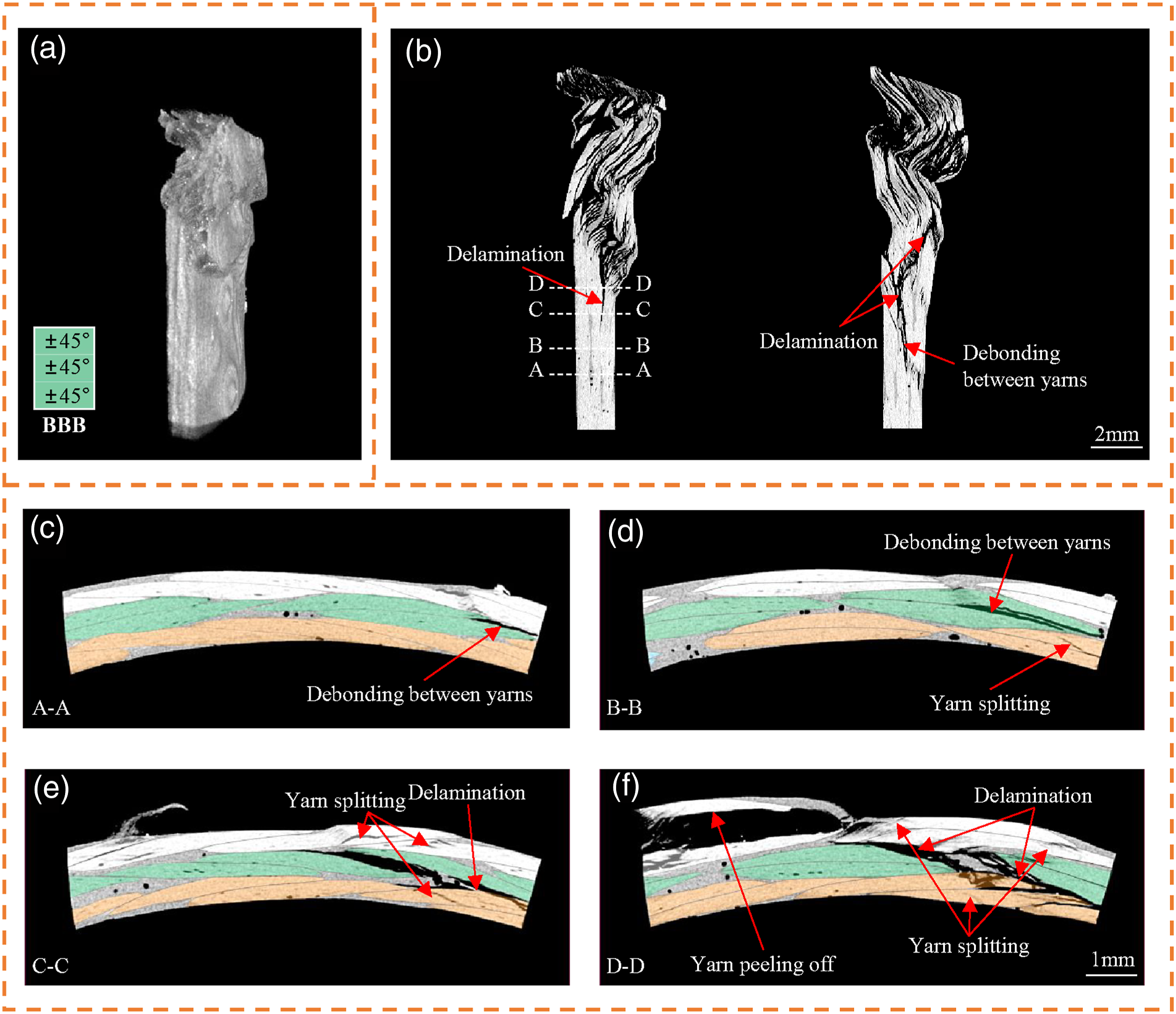

Debonding between yarns firstly appeared in the middle biaxial braided layer in the BBB tube as seen in Figure 8(c), caused by the torsion and shear deformation between the interlacing yarns under compression load as depicted in Figure 12. Under compression load, the braiding yarns were subjected to a multi-axial stress state, including axial compressive stress, transverse tensile stress, as well as in-plane shear stress with the braiding angle of 45°. Stress concentration intensified at the resin-rich yarn cross-over points until resin cracks appeared at this point and caused intra-yarns debonding. The crack was then rapidly expanded (Figure 8(d)) and grew into delamination between composite layers (Figure 8(e)). Delamination in two interface layers was finally formed in Figure 8(f). Relatively long inter-yarns debonding in the middle braided layer and two interfacial delaminations were also observed in the damage morphologies along the longitudinal direction in Figure 8(b). In addition, yarn splitting was initiated in the surface layers (Figure 8 (d) and (e)). However, the propagation of the yarn cracks was suppressed by the interlacing yarns as seen in Figure 8(f) and the yarns remained relatively intact even after inter-yarns debonding and delamination. Yarn peeling off was observed on the outer surface after inter-yarns debonding. From the cross-sectional damage morphologies, it was found that the damage cracks induced by inter-yarns debonding progressed rapidly in longitudinal and circumferential directions and eventually grew into delamination. However, the propagation of intra-laminar yarn crack was constrained by the special interlacing pattern. After delamination, the composite layers with relatively intact yarns were prone to local buckling, leading to a declined material utilization. Torsion and shear deformation between interlacing yarns in BBB tube.
Yarn splitting and delamination appeared almost simultaneously in the UUU tube specimen as shown in Figure 9(c). The yarn cracks rapidly developed in composite layers due to no interlacing patterns (Figures 9(d)–(f)), and widespread yarn cracks were observed in Figure 9(f). It was also found that the damage cracks were mainly concentrated near the crushing zone and long delamination crack was barely produced along the longitudinal direction in Figure 9(b). As a result, the unidirectional braided layers with extensive intra-laminar cracks tended to fold under an axial compression load, leading to a stable progressive folding damage process. Sectional damage morphologies of UUU tube: (a) 3D image, (b) longitudinal cross-section and (c–f) circumferential cross-section.
For the BUB tube, inter-yarns debonding and yarn splitting firstly appeared in surface biaxial braided layers (Figure 10(c)). Next, the yarn splitting in the middle unidirectional braided layer took place and delamination between biaxial and unidirectional braided layers was also observed in Figure 10(d). The delamination progressed fast both in circumferential and longitudinal directions (Figure 10 (b) and (e)–(f)). Obvious longitudinal delamination cracks were presented in Figure 10(b). The yarn cracks in the middle unidirectional braided layers easily developed and grew into delamination, while the surface biaxial braided layer suppressed intra-laminar yarn crack propagation and caused bending and local buckling of the structures (Figure 10(f)). Overall, the introduction of a unidirectional braided layer enhanced the load-bearing capacity and crushing stability of the BUB tube compared to the BBB tube. Sectional damage morphologies of BUB tube: (a) 3D image, (b) longitudinal cross-section and (c)–(f) circumferential cross-section.
Yarn splitting firstly occurred in the inner unidirectional layer in the UBU tube as shown in Figure 11(c). Next, yarn splitting was initiated and developed in the outer unidirectional braided sub-layer, and delamination took place (Figure 11(d)). Yarn cracks propagated along the yarn edges and eventually grew into delamination between the composite layers (Figure 11(e)). The delamination was mainly distributed at the interface between the B-U composite layers and inner U-U plies (Figure 11(b) and (f)). It was also clearly observed that the middle biaxial braided layer in the UBU tube produced more yarn cracks contributing to carrying compression load and dissipating crushing energy compared to that in the BBB tube (Figure 11(b) and (f)). As mentioned before, the easily progressed intra-laminar cracks in the surface unidirectional layers promoted the folding of the whole structure.
Crashworthiness
The comparisons of crashworthiness characteristics between braided tubes with different stacking sequences are illustrated in Figure 13. Furthermore, to better compare the crashworthiness performance of composite tubes with different wall thicknesses, the crashworthiness characteristics including peak load, mean load, and energy absorption were divided by the cross-sectional area of the braided tube, i.e., peak stress, mean stress, and energy absorption per unit area as shown in Figure 14. Despite the higher peak load of the UUU specimen than the BBB tube, the thicker wall induced an obviously lower peak stress. For hybrid tubes, the peak stress of the BUB tube was significantly lower than other configurations, that is 16.6%, 10.6%, and 3.5% lower than BBB, UBU, and UUU tubes, respectively, which is preferable for an excellent energy absorption structure. For ensuring the safety of the passengers in a vehicle, the high amount of peak load transmitted to the passengers should be reduced.72,73 The mean load and energy absorption capacity was related to the damage behavior of the braided tube. Despite more lobs formation and more regular folding damage behavior in the UUU tube resulting in 23.8% higher mean load and energy absorption compared to the BBB tube, whose tube wall was prone to local buckling, the mean stress and energy absorption per unit area of UUU tube were 2.2% lower. The energy absorption capacity was improved for hybrid tubes compared with BBB tubes, i.e. 22.4% and 20.4% higher energy absorption for BUB and UUB tubes, respectively, attributed to a more stable folding process induced by easier propagation of intra-laminar cracks, as well as splitting behaviors occurred during damage process which dissipated more crushing energy. In particular, the energy absorption per unit area of the UBU tube was 13.0% higher than the BBB tube. Moreover, the crush force efficiency of the BBB tube was the lowest, i.e. 0.74. The CFE value of the BUB and UBU tubes were 0.90 and 0.89, respectively, slightly higher than that of the UUU tube, which was 0.84. The higher CFE values of hybrid tubes were attributed to the relatively lower peak load, more stable crushing process and accompanied spitting behavior induced higher mean load. Crashworthiness characteristics of braided tubes: (a) Crashworthiness per unit area, including peak stress, mean stress and energy absorption per unit area.

Overall, the hybrid tube UBU presented obviously enhanced crashworthiness performance than other configurations under axial compression. The energy absorption capacity and energy absorption per unit area were 20.4% and 13.0% higher than pure biaxial braided composite, respectively. However, in previous study, 47 the hybridization effect of the UBU tube was not obvious in improving the impact resistance, while braided tube BUB yield the highest impact resistant capacity. Therefore, the investigation of the hybridization effect on impact damage tolerance or residual crashworthiness of hybrid braided tubes under compression after impact is necessary to be conducted in future work.
Conclusions
In this study, the failure behaviors of composite tubes made of hybrid biaxial and unidirectional braided layers under axial compression were investigated. The Micro-CT images for braided composite specimens conducted right after the second peak load identified the initiation and propagation of damage cracks during the compression process, which helped to exploit the failure mechanisms.
It was found that under axial compression the energy absorption capacity of braided tubes was related to the concomitant damage behaviors during the progressive folding process, which were governed by the crack propagation characteristics of different reinforced layers. The easily progressed intra-laminar cracks in unidirectional layers promoted splitting damage features in hybrid tubes. As a result, the UBU tube presented enhanced crashworthiness performance than other braided configurations, i.e., 20.4% and 13.0% higher energy absorption and energy absorption per unit area than pure biaxial braided tube, respectively. The lower crashworthiness of BBB tube was caused by local buckling damage feature attributed to interlaced yarns induced constrained intra-laminar crack propagation and tendency to delamination.
In addition, the investigation of the hybridization effect on impact damage tolerance or residual crashworthiness of hybrid tube under compression after impact is necessary to be conducted in future work.
Footnotes
Declaration of conflicting interests
The author(s) declared no potential conflicts of interest with respect to the research, authorship, and/or publication of this article.
Funding
The author(s) disclosed receipt of the following financial support for the research, authorship, and/or publication of this article: This work was supported by the National Natural Science Foundation of China [grant numbers 51775514, 51705466]; and Zhejiang Provincial Natural Science Foundation of China [grant numbers LR18E050001, LGG20E050015].
Data availability statement
The raw/processed data required to reproduce these findings cannot be shared at this time as the data also forms part of an ongoing study.