
Abstract
3D woven composites offer various high-performance characteristics and wide applications due to their lightweight, high strength, and good integrity. However, to exploit their structural advantages, it is necessary to improve the interface properties between reinforcement and matrix, and carbon nanotubes with excellent mechanical properties provide a good solution to improve the interface properties of composites. Based on this motivation, the goal of this study is to investigate the impact of multiwalled carbon nanotubes on the tensile and bending properties of basalt fiber through-angle interlocking 3D woven composite, layered-angle interlocking 3D woven composite and orthogonal 3D woven composite. The obtained results indicated that the maximum warp and weft tensile loads of the layered-angle interlocking composites increased by 19.3% and 28.5% from 91,091.3N and 8,409.5N to 9,288.4N and 11,761.4N, respectively. The maximum warp and weft bending loads of 3D orthogonal composites were increased by 26.4% and 19.6% from 566.7N and 635.4N to 770.0N and 790.3N, respectively. O-MWCNTs contain -OH, -COOH and the unsaturated double bond can active functional groups and basalt fiber on the surface of the Si-OH and unsaturated double bonds in the reaction to form epoxy resin covalent bond to improve the interface between the fiber and matrix effect, which solved the key problem of interface outstanding performance of 3D woven modified-basalt fiber composites.
Keywords
Introduction
Due to the good structural integrity, excellent interlayer performance, high strength, and high modulus of 3D woven composites, it is widely used in aerospace, construction, marine ship, and other fields.1,2,3 In recent years, high-performance fiber is usually used to prepare composite materials, with the increasing demand for biodegradable and recyclable materials, basalt fiber as a green and environmentally friendly high-performance fiber,4,5 gradually possesses a better market prospect. Compared with other commonly used high-performance fibers, basalt fibers have the advantage of lower cost, good mechanical properties, corrosion resistance, and friction resistance. Although various 3D structural preforms have obtained excellent mechanical properties, 6 the composites still have relatively weak interface properties, which is mainly due to the smooth surface of the fiber or yarn used to weave the preforms and the weak interface properties between the preforms and the matrix. 7 This defect of basalt fiber will hurt the mechanical, thermal, and tribological properties of composites.8,9
The in-plane properties of 3D woven composites depend on the interlacing of fibers and the connection between resin and fibers, etc. When subjected to loads, 3D woven composites are prone to failure under load, resulting in the decline of mechanical properties and stability. 10 However, there is no mutual binding and connection between layers of traditional laminated composites, which leads to easy stratification and low stability of traditional laminated composites. Therefore, 3D woven composites have better mechanical properties. Compared with metal materials, basalt fiber composite materials have good corrosion resistance, sun resistance, and lighter weight than metal materials can replace metal materials widely used in the engineering field.
Yang et al. 11 conducted split loading and tomography into ultrahigh performance fiber reinforced concrete (UHPFRC) specimens and found from the internal microstructure of fracture that the damage and fracture mechanism of materials included the bending and pulling out of fibers, the spalling, and fracture of the matrix, and the evolution of microcracks to macroscopic cracks. Ayyagari et al. 12 studied the interfacial properties of carbon fiber-reinforced polymer composites and found that composites were easy to delaminate due to poor interfacial properties. Wei et al. 13 showed that the warp yarn was directly broken and the weft yarn was also pulled out when the 3D woven composites material was damaged. Li et al. 14 used an SRCT scanner to continuously record the initiation and propagation of damage cracks in 3D woven composites and found that the interfacial properties were the main factors affecting the strength of the composites. Wu et al. 15 studied the in-plane compression properties of OWC, and the results showed that the failure mode was characterized by extensive debonding and delamination between the matrix and the yarn. To further improve the interface properties of composites, we need to modify the fiber or resin to better bond them together, reduced the generation of microcracks between the reinforcement material and the matrix, and prevent the disintegration between the composite layers.
Nano-materials have become an indispensable toughening material in the field of composites, which can effectively improve the surface activity of basalt fibers without damaging the fiber skeleton.16,17,18 Carbon nanotube (CNT) with excellent properties such as high aspect ratio, high mechanical strength, friction resistance, fatigue resistance, and electrical conductivity can be used as an ideal secondary reinforcement material.19,20,21 Using CNT in 3D woven fabrics can improve the interface bonding state of 3D woven composites and thus improve the structural continuity of 3D woven modified composites. 22 When the composites are stressed, CNT with the hollow structure first absorbed energy and produced elastic deformation, thus alleviating the serious damage caused by large stress to the fibers.23,24,25 On the other hand, the addition of CNT reduced the gap and defect between the reinforcement and the matrix and further improved the interface properties of 3D woven composites.26,27,28 CNT can effectively prevent interfacial slip, thus significantly improving the interfacial properties. 29
At present, the common user interface modification methods for 3D woven basalt fiber composites mainly focus on acid-base etching modification, plasma modification, coupling agent modification, and other methods.30,31,32 There are few studies on the preparation of 3D woven composites by modifying 3D woven fabrics with nanoparticles. Therefore, in this paper, carboxylated multiwalled carbon nanotube (O-MWCNT) modified by coupling agent KH570 is used to modify 3D woven fabric to improve the interfacial bonding performance of modified-basalt fiber 3D woven composites.
Experimental
Raw materials
800tex basalt fiber filament yarn from Zhejiang Jinshi Co., Ltd. was selected as warp and weft yarn of 3D woven fabric. The epoxy resin and curing agent system used as the matrix material from Hangmo New Material Group Co., Ltd, Version: VCuring agent= 100:85. The multiwalled carboxyl carbon nanotubes used to modify 3D woven fabrics in this study were provided by Nanjing Xianfeng Nanotechnology Co., Ltd. The 3-(isobutyl) propyl trimethoxysilane KH570 modified by multiwalled carboxyl carbon nanotubes was obtained from Shanghai Leading Biochemical Technology Co., Ltd. The anhydrous ethanol used to prepare the solvent from Tianjin Fuyu Fine Chemicals Co., LTD., and the Ice acetic acid used to adjust the pH of the solution from Tianjin Guangfu Technology Development Co., Ltd.
Sample preparation
Perform design and weaving
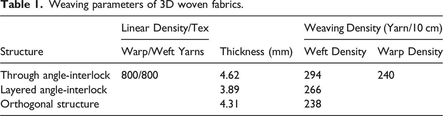
3D woven fabrics selected in this study with three different structures were designed and woven at a low cost on the ordinary loom. The schematic of warp cross-section and chain drafts of 3D woven fabric were shown in Figure 1. The buckling lines represented warp yarn and circles represented weft yarn. By lifting different heald frames in the weaving process, the warp and weft were interwoven, and the 3D woven fabric was successfully woven on ordinary loom. According to the weft yarn in Figures 1 (a), (c), and (e), it can be determined that 3D woven fabrics were 7-layer fabrics. The schematic of warp cross-section and chain drafts of 3D woven fabric (a) Cross-section schematic of TAWC (b) Chain draft of TAWC (c) Cross-section schematic of LAWC (d) Chain draft of LAWC (e) Cross-section schematic of OWC (f) Chain draft of OWC.
Weaving parameters of 3D woven fabrics.
Preparation of 3D woven modified-basalt fiber
Firstly, the O-MWCNT was functionalized with KH570, and the specific process was as follows: the mixed solution (80 ml) of anhydrous ethanol and deionized water with a ratio of 4:1 (v/v) were prepared, and its pH value was adjusted to 3.5–4.5 by hydrochloric acid, and KH570 was added in above solution and left for 1 h to obtained hydrolyzed KH570. O-MWCNT (300 mg) was dispersed into the above mixture. It was reacted at 60°C for 4 h, heated at 80°C for 12 h, and dried at 120°C for 4 h. After that, collected the O-MWCNT was modified by KH570 (KH570/O-MWCNT) via filtration, washing, and drying, respectively.
Secondly, KH570/O-MWCNT solution consisting of anhydrous ethanol and deionized water was prepared, and its pH was adjusted to 3.5–4.5 by hydrochloric acid, and then KH570/O-MWCNT (0.1% by weight of 3D woven fabric) was added to the above solution. Stirred the mixture equably for 10 min at room temperature and ultrasonic stirred at 35°C for 1 h, then formed the KH570/O-MWCNT solution. Finally, 3D woven fabrics were immersed in the above solution for 24 h and dried at 120°C. Figure 2 showed the modification process of 3D woven fabric. The modification process of 3D woven fabric by KH570/O-MWCNT.
Preparation of 3D woven modified-basalt fiber composites
Vacuum-assisted resin transfer molding(VARTM) process was used to solidify and shape the above modified 3D woven fabric. Figure 3 showed the schematic diagram of the VARTM process. The ratio of the resin and curing agent was 100:85. The amount of resin and curing agent prepared was just enough to soak the fabric completely. The prepared resin and curing agent were mixed in a beaker and mechanically stirred. After vacuum defoaming for 2 h in a vacuum drying oven at 60°C, the resin and curing agent mixed solution without bubbles were obtained. Put the 3D woven fabric modified by KH570/O-MWCNT into the mold, closing the vacuum bag to ensure no air leakage. Then, the resin solution was injected into the mold. The injection process was continued until a sufficient resin volume was seen in the resin trap to indicate that the mold had been filled with resin. The mold was placed in a blast oven for high-temperature curing. The temperature used in the curing process was divided into three steps: the first step was 2 h at 90°C, the second step was 1 h at 130°C, and the final step was 4 h at 140°C, as shown in Figure 4. Schematic diagram of the VARTM process. High-temperature curing process diagram of 3D woven composite.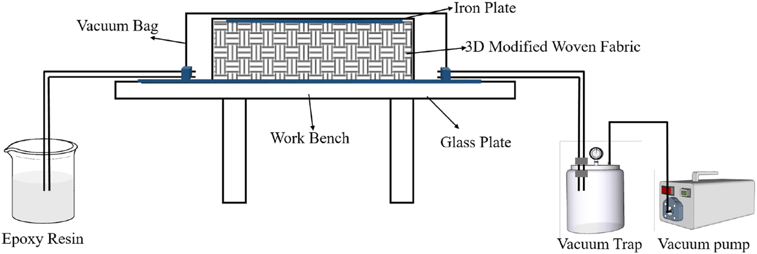

Characterization methods and tests
Fourier transform infrared spectrometer (FT-IR Platinum Elmer Instruments co., Ltd.) and energy dispersive spectrometer (EDS) on the SEM was used to characterize and surface the chemical composition of O-MWCNT and 3D woven fabric modified by KH570/O-MWCNT. The morphology features and fracture surface of the composite specimens were performed onfield emission scanning electron microscopy (SEM, JSM-7800F, Hitachi). Tensile and Bending performances of the composites were conducted on the universal electronic testing machine (TH-8102S.) according to the standard of GB/T 1447-2005 and GB/T 1449-2005 respectively. The tensile test speed was 10 mm/min, bending test speed was 2 mm/min. Finally, the load-displacement curves were obtained. The specimen geometry of composite materials were shown in Figure 5, where (a) was the specimen geometry of tensile and (b) was the specimen geometry of bending. The schematic diagram of the tensile test and bending test were shown in Figure 6, where (a) was the tensile test schematic diagram and (b) was the bending test schematic diagram. The tensile and flexural properties of the material were tested three times, respectively, and the average value was calculated. The sample thicknesses of the three structures were shown in Table 2. In addition, if the composite was tested according to ASTM test standards, the tensile and bending standards were ASTM D3039 and ASTM D7264, respectively. The specimen geometry of composite materials. (a) Tensile (b) Bending. The schematic diagram of the tensile and bending test. (a) Tensile (b) Bending. Tensile and bending specimen thickness.


Results and discussions
Structure characterization of KH570/O-MWCNT and 3D woven fabric modified by KH570/O-MWCNT
The strong adsorption effect between MWCNT made it difficult to disperse, thus, other chemical groups were introduced to produce spatial repulsion and improve the dispersion and surface activity of MWCNT. Figure 7(a) showed the hydrolyzed structure of coupling agent KH570. The side group of KH570 is hydrolyzable and can generate a large number of silanol bonds to react with the carboxyl group in O-MWCNT, while the other end of KH570 contains unsaturated double bonds, providing an active site for it to bind with epoxy resin, as shown in Figure 7(b). Reaction mechanism of O-MWCNT modifying (a) Hydrolysis KH570 (b) O-MWCNT modified by KH570.
As shown in Figure 8, the FT-IR spectrum of O-MWCNT mainly included the stretching vibration peak at 3439 cm−1, allotting to -COOH in O-MWCNT and -OH in adsorbed water molecules. The peak at 1629 cm−1 was the vibration peak of the C=C conjugated double bond of O-MWCNT, indicating that there were a lot of oxygen-containing functional groups such as -OH, -COOH, and C-O-C in O-MWCNT. After modified by KH570, a new peak was found at 1092 cm−1, which was the stretching vibration peak of Si-C and Si-O, and a bending vibration peak of Si-O and C-O was found at 625 cm−1, indicating that O-MWCNT was successfully modified by KH570. FT-IR spectra of O-MWCNT, KH570/O-MWCNT, 3D woven fabric (BF), KH570/O-MWCNT/BF.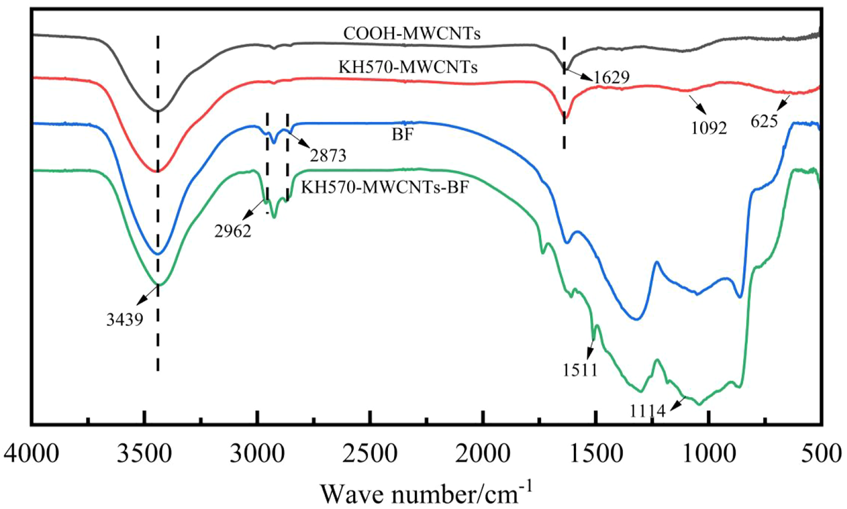
There were stretching vibration peaks of -CH2 of coupling agent and C-H group of an alkyl group at 2962 cm−1 and 2873 cm−1 of 3D woven fabric modified by KH570/O-MWCNT. This was due to the modification of O-MWCNT by KH570. At 864-1300 cm−1, there was a strong and wide absorption region, which was because more O-MWCNT existed on the 3D woven fabric surface, and they could lock with the silicon hydroxyl group on the 3D woven fabric surface and exist in the form of Si-O-Si bond. Therefore, the number of active functional groups on the surface of 3D woven fabric increased, which provided a large number of active sites for it to bind to the resin, and improved the interface properties of the composites. 33
Figure 9 showed the EDS images of O-MWCNT, KH570/O-MWCNT, BF and KH570/O-MWCNT/BF, and their content of characteristic elements were presented in Table 3. It could be found that C, O, Si, and a small amount of N emerged in O-MWCNT, while the content of Si in the O-MWCNT modified by KH570 increases obviously. BF itself contains less C element, but after KH570/O-MWCNT modification, the fabric contains a large amount of C element in KH570/O-MWCNT, which is mainly due to the large amount of C element in KH570/O-MWCNT. As shown in Figure 9(b), elements in the O-MWCNT modified by KH570 were evenly distributed, and the Si element increased in the O-MWCNT modified by KH570 and in Figure 9(d), the C element increased in the BF modified by KH570/O-MWCNT. Therefore, combined with the result of FT-IR, the silane coupling agent of KH570 has been successfully modified on the surface of O-MWCNT and KH570/O-MWCNT has also successfully modified on the BF. EDS images of O-MWCNT, KH570/O-MWCNT, BF, KH570/O-MWCNT/BF (a) O-MWCNT (b) KH570/O-MWCNT (c) BF (d) KH570/O-MWCNT/BF. The element content of O-MWCNT, KH570/O-MWCNT,BF and KH570/O-MWCNT/BF.

Morphology analysis of KH570/O-MWCNT and modified 3D woven fabric
Figure 10 showed SEM images of O-MWCNT, KH570/O-MWCNT, 3D woven fabric, and 3D woven fabric modified by KH570/O-MWCNT. As shown in Figure 10(a), unmodified O-MWCNT was relatively coarse and long, and they intertwined with each other, resulting in relatively close stacking. This was because the chemical bonds on the surface of the unmodified O-MWCNT were less, and it was not easy to adsorption and mutual reaction between the chemical bonds. In Figure 10(b), the length and diameter of O-MWCNT modified by KH570 became shorter and coarsely, and many parts were truncated, which endowed the O-MWCNT modified by KH570 with better dispersibility. Because of the introduction of KH570, the functional groups on the surface of O-MWCNT reacted with KH570 to form new chemical bonds, and the strong interaction and winding phenomenon between O-MWCNT were weakened, which was beneficial to the dispersion and stability of O-MWCNT. SEM images (a) O-MWCNT (b) KH570/O-MWCNT (c) 3D woven fabric (d) 3D woven fabric modified by KH570/O-MWCNT (e) The magnified image.
The surface of unmodified 3D woven fabric was relatively smooth. As shown in Figure 10(c), the 3D woven fabric surface was not fully dumped resulting in a few bumps, but the 3D woven fabric surface showed relatively smooth. After modification, KH570/O-MWCNT grows on the surface of the 3D woven fabric-like roots, resulting in the rougher surface of 3D woven fabric, as shown in Figure 10(d). The magnified image of the modified 3D woven fabric modified in Figure 10(e) indicated that the surface roughness of the 3D woven fabric increased. KH570/O-MWCNT has a large amount of -OH, while basalt fiber surface has fewer functional groups, but it contains a large amount of Si-OH, which can react with -OH on the KH570/O-MWCNT so that the KH570/O-MWCNT was successfully grafted to the surface of the basalt fiber, forming uneven surface properties. Meanwhile, KH570/O-MWCNT contains unsaturated double bonds which can react with the functional groups in the resin matrix. The rough-faced basalt fibers also engaged mechanically with the resin, successfully improving the interfacial interaction of the composites.
Mechanical properties of 3D woven modified-basalt fiber composites
Tensile properties of 3D woven modified-basalt fiber composites
Due to the different fiber orientations in the 3D woven composites, the reinforcement effect of the composites varied in different directions. Therefore, the warp and weft tensile properties of basalt fiber 3D woven composites with different structures, unmodified and modified by O-MWCNT were tested respectively. The load-displacement curves were obtained, as shown in Figure 11, where (a) was the weft tensile load-displacement diagram and (b) was the warp tensile load-displacement diagram. The figure showed that the load-displacement curves of each composite material under both warp and weft tensile action were divided into two stages. The first stage was the initial loading stage, in which the curve increased almost linearly. In the initial loading stage, the sample first self-locks. On the other hand, there are bubbles on the surface or inside the material in the process of preparation resulting in material uneven, which leads to a weak load on the defective part of the material and fractures first. So the curve can not show a strict linear growth. Therefore, the load-displacement curve showed certain errors in the early stage. At this stage, the main load was borne by the yarn and resin matrix. With the load increased gradually, presenting different degrees of microcracks on the sample.
34
In the second stage, the tensile load continued to increase, and the curves all tend to nonlinear increase, which was due to the gradual failure of the fiber in the composite. When the stress reached a certain level, the matrix cracks, and the strain concentration area increases. In addition, the inner yarns eventually reached their maximum carrying capacity, they were completely damaged until the fibers broke or were completely pulled out of the matrix.
35
Tensile load-displacement curves of 3D woven basalt fiber composites and 3D woven modified-basalt fiber composites (a) Warp direction (b) Weft direction.
The maximum warp direction tensile load of unmodified TAWC, LAWC, and OWC was as follows: 8198.7 N, 7783.8 N, 8196.4 N. The maximum warp direction tensile load of TAWC, LAWC, and OWC modified by KH570/O-MWCNT was as follows: 9501.9 N, 9288.4 N, 9405.4 N. They were increased respectively by 15.9%, 19.3%, and 14.8%. At the same time, the maximum weft direction tensile load of unmodified TAWC, LAWC, and OWC was as follows: 11,662.9 N, 9151.2 N, 8654.8 N. The maximum weft direction tensile load of TAWC, LAWC, and OWC modified by KH570/O-MWCNT was as follows: 14,371.3 N, 11,761.4 N, 10,404.9 N. They were increased respectively by 23.2%, 28.5%, 20.2%. Combined with the maximum load of warp and weft directions tensile tests, TAWC could bear the maximum load among the three structures.
Bending properties of 3D woven modified-basalt fiber composites
The 3D woven composites and 3D woven modified-basalt fiber composites with the above three different structures were tested by three-point bending on a universal test machine, the load-displacement curves were divided into three phases shown in Figure 12. During the initial loading phase, the curve increased almost linearly. At the beginning, the damage distribution was mainly focused on the point where the pressure head was located. But it can be seen from the curve that small kinks were generated at the initial stage, mainly because bubbles may accumulate on the surface of the composites during the preparation process, which made the composites surface slightly rough. Therefore, small kinks were generated due to poor contact between the composites and the test chuck during the testing process. In the first stage, with the increase of displacement, the damaged area increased gradually and the material as a whole was under stress and inelastic deformation at this stage. In the second stage, the curve no longer presented straight lines and the slope of curves decreased with the increase of displacement. This was because as the loading continued, micro-cracks gradually appeared on the surface of the material, and the cracks gradually propagated. At the same time, the matrix gradually cracked, and the fibers were gradually pulled out until the maximum load was reached. In the third stage, after reaching the peak value, the curve drops rapidly and the final brittle fracture occurred. A large number of fibers were pulled out, and the matrix was transformed from local microcracks to monolithic fractures.36,37 Bending load-displacement curves of 3D woven basalt fiber composites and 3D woven modified-basalt fiber composites (a) Warp direction (b) Weft direction.
The maximum warp direction bending load of the unmodified TAWC, LAWC, and OWC was as follows: 668.1 N, 661.2 N, 608.9 N. The maximum warp direction bending load of TAWC, LAWC, and OWC modified by KH570/O-MWCNT was as follows: 866.4 N, 791.2 N, 770.0 N. They were increased respectively by 29.7%, 19.7%, and 26.4%. At the same time, the maximum weft direction bending load of unmodified TAWC, LAWC, and OWC was as follows: 991.8 N, 661.9 N, 660.8 N. The maximum weft direction bending load of TAWC, LAWC, and OWC modified by KH570/O-MWCNT was as follows: 1119.8 N, 787.4 N, 790.3 N. They were increased respectively by 12.9%, 18.9%, and 19.6%.
Fracture damage mechanism of the composites.
The tensile fracture failure mode of the composite before and after modification was observed as shown in Figure 13. Under the action of load, the yarn buckling of the 3D woven composites was first produced because the 3D woven fabric was the reinforcement of the materials. With the continuous increase of load, the yarn buckling increased, and then the yarn was gradually pulled out until the yarn reached the maximum stress limit and shear failure occurred.
38
It can be seen that the fracture section of unmodified 3D woven composites was rough, the length of the fiber pulled out was not uniform, and the fracture fiber surface was smooth, indicating that the interface property between basalt fiber and resin was weak.
39
It can be seen from Figure 13(b) that when the specimen is broken, most of the matrix at the fracture point falls off, and only a small part of the resin remained on the fiber surface. However, the fiber length of 3D woven modified-basalt fiber composites was relatively consistent, without obvious fiber pulling and most of the resin remained on the fiber surface. It can be seen from Figure 13(c) that fiber pulling was reduced at the fracture of the composite modified by KH570/O-MWCNT, indicating that the interface load transfer capacity of the basalt fiber 3D woven composites modified by KH570/O-MWCNT was weakened, and crack transmission at the interface was inhibited. It improves the strength properties by limiting the fiber extraction, as well as the propagation of cracks, due to the mechanical locking formed by the particles with the epoxy. It can be said that the multi-walled hollow morphology and high specific surface area of O-MWCNT increase the contact area between fiber and matrix, which is conducive to enhancing the good adhesion between material and resin.
40
Therefore, the mechanical properties of basalt fiber 3D woven composites were improved. Fracture section SEM photograph of the specimen (a) Unmodified specimen (b) The magnified image (c) Specimen modified by KH570/O-MWCNT (d) The magnified image (e) Fracture morphology of composites.
Combined with the particles attached to the fiber surface pulled out at the fracture of the composite material, it was found that the KH570/O-MWCNT modified composite material has more resin particles attached to the surface of the pulled fiber, which proved that the dispersion of KH570/O-MWCNT in the composite material was good.
The bending fracture failure mode of the composite before and after modification was that the resin and fibers on the upper surface were buckling and deformed due to bending and extrusion. The resin matrix and yarn were cracked and expanded downward, and the resin matrix and fibers on the lower surface were subjected to tensile stress. The action produces transverse cracks and propagates upwards. In the tension part, the fibers were debonded from the resin, and the fibers were pulled out and broken. In the compressed part, the fiber and resin were separated, and the fiber lost support and buckling failure. The unmodified composite material has weak interfacial bonding, more fibers were pulled out at the fracture, and there were more pores caused by fiber pulling out. In addition, the fibers pulled out from the matrix were found to have relatively smooth surfaces, indicating that the interfacial interaction between the unmodified composite reinforcement and the matrix was weak, making it prone to interfacial debonding. However, the interface bonding effect of the composite modified by KH570/O-MWCNT was enhanced, the fiber pulling at the fracture was reduced, and the surface of the fiber pulled out from the matrix have more resin particles. This was mainly because the introduction of KH570/O-MWCNT formed a strong interfacial bond between the fiber and the matrix, which inhibited the expansion of cracks in the material, thereby enhancing the interfacial bonding effect of the composite. 41
Conclusions
In this paper, KH570/O-MWCNT reinforced basalt fiber 3D woven composites with different structures were prepared by the VARTM method. The mechanical properties were compared with that of unmodified basalt fiber 3D woven composites, the following conclusions are reached: The KH570/O-MWCNT modified fabric can react with Si-OH on the fabric surface to generate Si-O-Si, increasing the surface energy of the fabric and enhancing the interfacial bonding of the composite. The KH570/O-MWCNT modified fabric increased the Si element content in the fabric, and at the same time, the surface roughness of the fiber was significantly increased by SEM observation. Comparing the tensile properties of unmodified basalt fiber 3D woven composites, the addition of KH570/O-MWCNT can improve the warp and weft tensile loads of the three structural composites to varying degrees, The warp maximum tensile loads of TAWC, LAWC and OWC were 9501.9 N, 9288.4 N and 9405.4 N, which increased by 15.9%, 19.3%, and 14.8%, respectively. The weft maximum tensile loads were 14,371.3 N, 11,761.4 N, and 10,404.9 N, which increased by 23.2%, 28.5%, and 20.2%, respectively. Comparing the bending properties of unmodified basalt fiber 3D woven composites, the addition of KH570/O-MWCNT can improve the warp and weft bending loads of the three structural composites to varying degrees, The warp maximum bending loads of TAWC, LAWC and OWC were 866.4 N, 791.2 N and 770.0 N, which increased by 29.7%, 19.8%, and 26.4%, respectively. The weft maximum bending loads were 1119.8 N, 787.4 N, and 790.3 N, which increased by 12.9%, 18.9%, and 19.6%, respectively. The damage mechanism of the material is analyzed. The top surface fiber and matrix were squeezed and deformed, and the bottom surface fiber and matrix were stretched and deformed in bending loading. In the elastic tests, the top and bottom surfaces of the material were stretched first to produce elastic deformation, brittle fracture occurs when the material was beyond the elastic region. In addition, the 3D woven fabrics modified by KH570/O-MWCNT can inhibit the initiation and propagation of cracks and the pull-out of fibers, improving the mechanical properties of the 3D woven composites.
In general, the surface modification of basalt fiber 3D woven fabric by KH570/O-MWCNT in this study provides a simple and efficient surface modification method, which effectively improves the comprehensive properties of 3D woven composites.
Footnotes
Declaration of Conflicting Interests
The author(s) declared no potential conflicts of interest with respect to the research, authorship, and/or publication of this article.
Funding
The author(s) disclosed receipt of the following financial support for the research, authorship, and/or publication of this article: This research was funded by the National Science Foundation of Liaoning Province (1645749635925) and the Open Project Program of Ministry of Education Key Laboratory for Advanced Textile Composite Materials (Tiangong University) No. MATC-2021-003.