
Abstract
Stacking sequences of composite laminates have significant effects not only on the properties of composites but also on the types of damage occurred on the composites structure. The current study investigated the low velocity impact properties and the damage progression of kenaf core sandwich laminates in different layering sequence of fibre laminates. There were three different sequences of kenaf (K) and glass (G) fibre reinforced unsaturated polyester composites, that is, G/K/G hybrid, G/K/K hybrid and K/K/K composites, which were fabricated using hand lay-up method. The layer of gelcoat provided a protective layer and finishing to the composite. The composites experienced the low velocity impact at three different energy levels which were 5 J, 10 J and 15 J. Through the research, a diamond shape matrix cracking was exhibited on the gelcoat surface. The main failure mode that occurred on the specimen during the low velocity impact was matrix cracking, fibre breakage, delamination and fibre pulled-out. From the results, G/K/G hybrid resisted the highest impact energy which is up to 10 J and G/K/K hybrid resisted up to 5 J. Meanwhile K/K/K composite failed to resist any of designated energy. Therefore, it can be suggested that G/K/G hybrid composites had shown good performance in low velocity impact properties to be used as the bus bumper material.
Introduction
Stacking sequence of composite laminates can be altered to be in sandwich-structured considering its purpose in the targeted applications. Either focusing on the resistance of its outermost layer or enhancing its overall strength, natural-synthetic hybrid composites was seen to promote significant improvement in both aspects.1,2 Introducing a layer of glass fibre (G) each at the outermost top and bottom part of sisal (S) three layer composites (G/S/S/SG) had significantly improved the flexural strength from 124.64 MPa for S/S/S/S/S to 205.64 MPa for G/S/S/S/G. 3 Positioning carbon and basalt fibre either as core or skin in carbon/basalt hybrid composites showed significant different on its flexural strength and failure mechanism. Fibre breakage and matrix cracking was observed on carbon skin basalt core hybrid composites, while fibre-matrix de-bonding was exhibited in basalt skin carbon core hybrid composites. 4 Stronger fibre-matrix interaction, indicated by lower tan delta peak, can be achieved by positioning cotton as the core in cotton/glass hybrid composites (G/C/C/C/G) compared to glass as the core (C/G/G/G/C).5,6 The resistance of empty fruit bunch composites (pure EFB) towards moisture absorption was improved with the introduction of jute fibre (J) to replace the outermost layer (J/EFB/J). The void in the hybrid composite have been filled up by the fibre arrangement during hybrid composite fabrication, thus limit the moisture absorption. 7 Various combinations had been reported in developing natural-synthetic hybrid composites, not only in a sandwich-structured sequence, but also in alternate, symmetric and asymmetric sequences. Uni-directional (UD) flax fibre and cross-ply (CP) flax fibre had been hybrid with carbon fibre to evaluate the moisture absorption of the hybrid. The result showed that flax UD/carbon hybrid recorded the lower moisture absorption percentage which was 2% compared to flax CP/carbon hybrid which presented 8% of moisture absorption percentage. 8 Hybridizing kenaf/aramid fibre using alternate sequence showed the higher result of low velocity impact energy compared to non-alternate sequence of kenaf/aramid fibre hybrid composite. At 100 J of impact energy applied, the results of energy absorbed recorded were 72.99 J and 66.04 J for 17aramid/2kenaf hybrid (alternate) and 17aramid/2kenaf hybrid, respectively. 9 It was found that hybrid composites absorb more impact energy compared to pure kenaf composites at the same energy level. As for the stacking sequence, the placement of kenaf and aramid layers alternately could withstand higher impact loads compared to stacking kenaf layers and aramid layers separately. 9
Among all natural fibres reported to be used in composites and hybrid composites, kenaf was known to have high strength properties due to its high lignin content. 10 Various research studies had promoted the development and potential of kenaf in composites. Higher flexural strength of 85.56 MPa for 4:1 ratio of kenaf/empty fruit bunch was compared to 1:4 ratio of kenaf/empty fruit bunch composites with 61.61 MPa flexural strength. 11 In different study, increasing the fibre content of sisal/kenaf fibres from 10% to 40% in unsaturated polyester resin showed significant improvement of its tensile strength from 49.14 MPa to 91.33 MPa. 12 Besides ratio and loading of kenaf fibres in composites, the effects of chemical treatment on kenaf fibres were also actively reported. Comparing two main parameters of chemical treatment in a study suggested that different concentration of each chemical results in more significant difference in the composite tensile strength compared to the comparison on the types of chemicals used. 13 The study of kenaf fibres was also extended to the effects of non-woven and woven kenaf fibres on the tensile properties of kenaf reinforced epoxy composites. Significant improvement was found on the tensile strength of woven fibre composites compared to non-woven fibre composites. 14 As of today, numerous studies applying multiple parameters on kenaf composites had been reported, but researchers need to put more effort in filling the gap of impact properties of kenaf composites.
The study on impact properties of natural fibre composites is expanding with several types of natural fibres reported to date, such as jute, flax, hemp, sisal, bamboo and cotton.15–20 Cotton/bamboo hybrid composites with 45:55 ratios were reported to have the highest impact strength of 36.05 kJ/m2, while aloevera/sisal hybrid composites absorbed the highest 0.6 J impact energy.15,16 In two different studies, bamboo and jute fibres were applied in warp and weft directions in poly lactic acid (PLA) composites. It was found that bamboo/PLA in weft direction showed higher impact strength of 26.93 kJ/m2 compared to warp direction. 17 Opposite result was observed for jute/PLA composites, which jute in warp direction showed higher impact strength compared to weft with 18.1 kJ/m2 and 16.6 kJ/m2, respectively. 18
In parallel with the impact properties reported for various natural fibres discussed above, the impact studies on kenaf composites were also reported. Varying the orientation of kenaf fibre in PLA composites showed that randomly orientated fibre possessed the highest impact strength of 90.64 kJ/m2 compared to bidirectional and unidirectional oriented kenaf fibres.19,20 The effects of fibre loading on the impact strength of kenaf/sisal hybrid composites was studied, which the highest percentage of 40% fibre loading results in the highest impact strength of 22.3 kJ/m2. 12 The combination of kenaf/sisal hybrid composites was also reported in different study with two variations of stacking sequence, kenaf/sisal/kenaf (K/S/K) and sisal/kenaf/sisal (S/K/S). The effects of weathering on impact strength of both hybrid composites were reported accordingly. 21 In another study reported by Salman SD, 22 it was found that the overall dynamic mechanical properties of hydrid composites were dependent on the stacking sequence of the jute and carbon layers. The layers with the jute as its core and carbon as the outer layers (H1) had proven to have the best mechanical properties, compared to carbon as the core and jute as the outer layer (H2). Recently, an attempt to combine kenaf with glass fibre was also reported in deepening the understanding of its impact properties. The reported study suggested that 75:25 ratios of glass/kenaf where the outermost layer of the hybrid was glass fibre layer, can withstand impact energy up to 40 J without severe damages. 23
In the context of broadening the knowledge of impact properties and damage analyses on impacted samples, the current study was aimed to discuss both aspects with focusing on the damages after low velocity impact properties. Kenaf/glass hybrid composites in sandwich-structured laminates was proposed in this study to fill the gap of less impact studies been reported on kenaf composites as well as the preliminary studies to apply the proposed hybrid composites in automotive applications, mainly for bus bumper components. Since there are differences in fibre thickness, the proposed kenaf/glass hybrid composites within 3–3.5 mm thickness was fabricated in accordance to the actual thickness of bus bumper, which is 3 mm.
The proposed study is to support the use of green composites in various applications, that is, automotive. This preliminary study will lead to a bigger objective, considering the gap existed and future works needed to improve the output.
Experimental
Materials
General properties of unsaturated polyester resin.

General properties of gel coat.

General properties of kenaf fibre and glass fibre reinforced polyester composites.

Fabrication of kenaf/glass hybrid composites
In this study all composites were fabricated through hand lay-up method and cured in room temperature for 24 h. All the procedures applied were adapted from the industrial standard working procedures, which directly trained by the industrial personnel. Gelcoat mixed with MEKP hardener at 100:1 weight ratio was applied evenly using a brush on a steel plate and was left to set for 5–10 min. Unsaturated polyester resin was mixed with MEKP hardener at a ratio of 100:1 for the matrix of the composites. The mixed resin was poured onto the woven fibres, one layer at a time, and distributed evenly using a roller to wet the whole surface, thus reduce defects during fabrication. The wetted fibre laminates were pressed with another flat surface steel plate to apply pressure, thus removed excessive resin and trapped bubbles, which can lead to voids production in cured composites. The composites were left to cure at room temperature for 24 h.
Figure 1 shows the layering scheme of G/K/G hybrid composites, while Table 4 lists all the composites fabricated in this study. The fibre/matrix ratio applied for each composite was adapted from most reported studies on woven natural fibres and verified through several preliminary testing before the actual composites were fabricated. The thickness of all composites was approximately 3 mm. Schematic representation of G/K/G hybrid composites. Different layering sequences of composites.

Low velocity impact test
Rectangular specimens with dimension of 150 mm x 100 mm were cut from the prepared composite laminates. Low velocity impact test was conducted using a drop weight instrument, brand Imatek Ltd, type 8000D, model D5000, from Knebworth, UK and ASTM D 7136/D7136M-15 standard as the reference. The illustration of experimental setup was presented in Figure 2. The side that has gelcoat surface was facing the instrumental tup which means the gelcoat surface will become the impacted surface. In the manufacturing of bus bumper, gelcoat layer is the outermost layer of the bus bumper and become the impacted surface when the low velocity impact occurred during the operation. The illustration of experimental setup for low velocity impact testing.
The impact energy was adjusted according to Eq. 1:
Results and discussions
Force against displacement
The force against displacement of the three types of composites at three different energy levels 5 J, 10 J and 15 J are presented in Figure 3. The closed-loop curve occurred when the impactor hit the specimen, and then rebounded without penetrating the specimen.23,32 From Figure 3, all the graphs at the three different energy levels exhibited the opened-loop curve for the K/K/K composites which means that the composites cannot withstand the impact energy that had been applied. As a result, the specimens were severely damaged and were penetrated by the impactor. When a layer of kenaf fibre had been substituted with glass fibre and became a G/K/K hybrid composite the graph showed a slightly closed-loop curve at an energy level of 5 J while the other two energies showed the open-loop curve. The embedded kenaf fibre with two layers of glass fibre (G/K/G) presented the closed-loop curve of force against displacement graph at 5 J and 10 J. The hybridization with glass fibre enhanced the properties of the composite due to the better mechanical properties of synthetic fibre. In the previous study, embedded jute with glass fibre presented higher impact strength compared to jute composite and the result was recorded as 25 km/J2 and 19.4 km/J2, respectively.
33
Kenaf embedded with aramid hybrid composite also resisted the higher energy which was 2.5 J compared to aramid composite and kenaf composite which recorded as 2 J and 0.5 J, respectively.
34
From the trend, hybridization with synthetic fibre led to the increment of impact resistance of the composites. Force against displacement at (a) 5 J (b) 10 J and (c) 15 J of energy.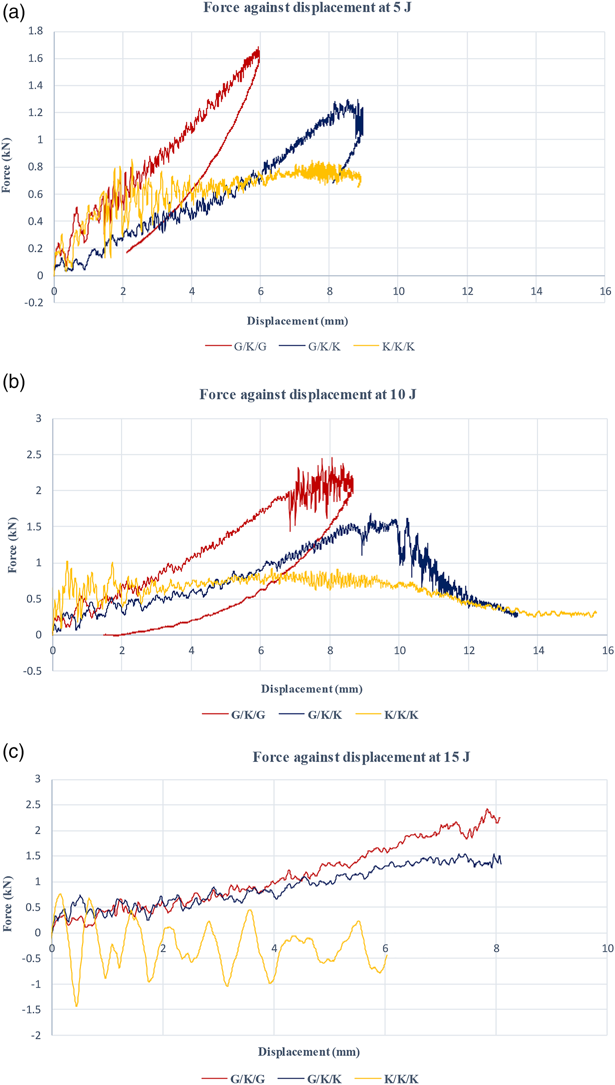
The ascending slope trend from the graph curve showed the impact bending stiffness of the specimens and the descending trend indicated the rebounding activity of the impactor after the impact had occurred.35,36 From Figure 3, it can be observed that there was an ascending slope in the G/K/G and G/K/K hybrid composites in each energy. This indicated that the glass fibre in the G/K/G and G/K/K hybrids provided the bending stiffness to the hybrid composites. The maximum displacement of the G/K/G hybrid for 5 J, 10 J and 15 J were 5.98 mm, 8.66 mm, and 8.08 mm, respectively. Meanwhile, the maximum displacement value for the G/K/K was 8.98 mm at 5 J followed by 13.42 mm at 10 J, and 8.10 mm at 15 J of energy. For the K/K/K composite specimens, the absence of glass fibre caused the irregular shape in the force against displacement graph at 5 J, 10 J and 15 J of energy. From the results, it is indicated that fully kenaf composite withstand lower energy than designated energy which were 5 J, 10 J and 15 J and exhibited the opened-loop curve at 5 J, 10 J and 15 J graphs. This result was similar to the results reported by Salman SD, 9 where the pure kenaf composites could not withstand higher impact energy compared to a hybrid composites. According to Majid et al., the oscillatory behaviour of the force in Figure 3(c) happened due to vibrational motions between the impactor and impacted surface. 28 It was reported that severe damage was found on the kenaf/epoxy samples compared to glass/epoxy and hybrid composite samples. As the energy level increases, the damages become more severe as shown by the increasing amplitude of the irregular oscillation. 28 In Figure 3(c), more irregular oscillation at 15 J indicated that the samples experienced severe damages. The graph also showed a slightly ascending slope for K/K/K composites at 5 J and 10 J of energy. The maximum displacement was 8.91 mm and 15.70 mm, respectively. This indicated that the bending stiffness still responded to the energy that had been applied but for 15 J of energy, there was no slope presented in the graph because the composite was completely penetrated by the impactor. The recorded maximum displacement for the K/K/K composite at 15 J energy was 6.04 mm.
Energy against time
The kinetic energy from the impactor was transferred to the specimen and was partially stored in an elastic deformation form. The rest of the energy is distributed as friction, sound, and heat energy when the damage on the specimen was developed.
34
As reported in other studies, in energy-time curve, the impact energy was determined by the peak value and flat line in the graph, which indicated the absorbed energy.35,36 Energy–time curve of the composites as shown in Figure 4(a) and Figure 4(b) were linearly increased with the time until the curve declined after it had reached the maximum peak load. Energy versus time at (a) 5 J (b) 10 J (c) 15 J energy impact.
Based on Figure 4, 5 J and 10 J of energy showed the increasing trend of the slope for all composite’s types. For the G/K/G hybrid composite, the time taken to reach the maximum peak energy was sooner than other composites which were indicated to be as soon as the impactor hit the hybrids, the impactor rebounded from the surface which led to minimal energy being absorbed by the hybrids. In 10 J energy against the time graph, the G/K/G hybrid composite presented a pattern showing that the energy increased and decreased before the graph had reached to the zero gradient of the graph’s slope. This pattern does not exist for the G/K/K and K/K/K composites. It can be concluded that G/K/G composite can still resist the impact energy at 10 J while the G/K/K and K/K/K composites experienced penetration by the impactor. Similar to the study reported by Salman SD, 9 it was found that large amount of energy are absorbed by hybrid composites compared to pure composites made of one type of material. Also, Salman’s study had also shown that the layering sequence of alternating the natural fibre mat (kenaf mat - K) and the synthetic fibre (aramid mat – A) mat tend to have better energy absorption compared to stacking the same type of material at one end such as A/K/K. 9
Impact properties of kenaf/glass hybrid composites.
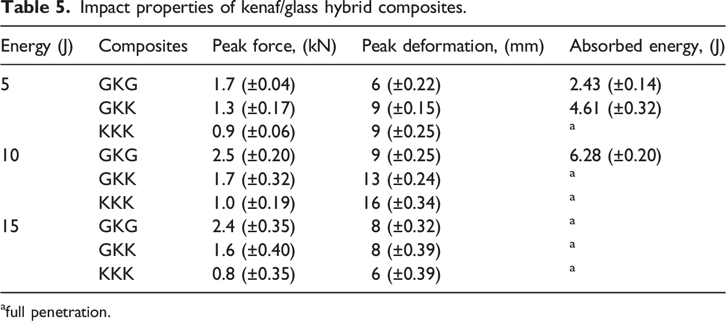
afull penetration.
Damage characterization
Elastic deformation, intra-laminar damage, matrix cracking and delamination were the damage mode that occurred because of the energy that was absorbed by the target when the impactor hit the specimen’s target.
35
The usage of the gelcoat had been described as the finishing and protective layer for the composite.
36
In this research, a thin layer of gelcoat was applied only on the front side of the composites. As are illustrated in Figures 5 to 7, the front side of the composites mostly presents the diamond shape of the matrix cracking. Also, the damage of the composite at the front side was not as severe compared to the backside of the composite. This circumstance indicates that the gelcoat act as the protecting layer to the composites. Damage characterization was determined through visual inspection. The damage of G/K/G hybrid, G/K/K hybrid and K/K/K composites at 5 J impact energy can be seen in Figure 5. Damage characterisation at 5 J impact energy; front side, (a) G/K/G hybrid, (b) G/K/K hybrid, (c) K/K/K composite; backside, (d) G/K/G hybrid, (e) G/K/K hybrid and (f) K/K/K composites. Damage characterisation at 10 J impact energy; front side, (a) G/K/G hybrid, (b) G/K/K hybrid, (c) K/K/K composite; back side, (d) G/K/G hybrid, (e) G/K/K hybrid, and (f) K/K/K composites. Damage characteristic at 15 J impact energy; front side, (a) G/K/G hybrid, (b)G/K/K hybrid, (c) K/K/K composite; backside, (d) G/K/G hybrid, (e) G/K/K hybrid and (f) K/K/K composites.


The K/K/K composite showed matrix cracking and also presented the transverse and longitudinal fibre crack at the top of the composite while fibre breakage only happened at the bottom of the composite. This failure mode explained the opened-loop curve of the force against displacement graph in Figure 3(a). 9 The G/K/K hybrid exhibited indention, matrix cracking and delamination on the top surface of the composite while the bottom showed the fibre breakage failure. For the G/K/G hybrid composite, there was a small dot of delamination on the top surface of the hybrid caused by the impactor but the matrix cracking and delamination failure modes were exhibited at the bottom of the hybrid. From the research made by Salman SD, 9 it was found that pure kenaf composites absorbed the least energy which causes the largest surface damage on the samples. As the energy absorbed by the samples increases, less amount of damage could be seen on the samples. This is similar to result obtained in this study. However, unlike in this study, there was no visible penetration accrued on the samples in Salman’s study, which is probably due to the amount of Kenaf layers used. The damage of specimens at 10 J is illustrated in Figure 6.
The transverse and longitudinal crack of the K/K/K composite was larger when 10 J impact energy was applied compared to 5 J of impact energy. The composite also exhibited the matrix cracking and fibre breakage. The G/K/K hybrid presented the perforation on the top of the hybrid and fibre breakage at the bottom of the hybrid. The force against displacement graph in Figure 3(b) showed the closed-loop curve which was described by the damage of the G/K/G hybrid composite. The hybrid was not fully penetrated by the impactor but the hybrid did experience the failure modes such as indention, delamination and matrix cracking.
The visual inspection of the composites gave the supporting explanation for force against the displacement graph. The composites experienced the full penetration at 15 J of impact energy as shown in Figure 7, while the graph in Figure 3(c) presents the opened-loop curve. The specimens exhibited the failure mode such as glass fibre pulled-out, delamination, fibre breakage and matrix cracking.
The K/K/K composite experienced the most severe damages with the largest area being affected through matrix cracking and fibre breakage. There was no additional protection on the front side of the composite which could help in slowing down the damage propagation towards the backside, thus resulting to a complete penetration and delamination. It also shows a brittle like damage since no fibre pull-out are visible on top of the backside composite. Interestingly, adding one layer of glass fibre at the top surface of G/K/K hybrid reduced the brittleness of composites at the top while the bottom layer of the kenaf fibre completely broke. This shows that the glass fibre of the G/K/K composite was able to absorb a certain amount of energy to prevent complete penetration. However, it was not enough to stop the damage propagation to travel through the glass fibre and penetrate the Kenaf layer at the backside of the G/K/K hybrid, which causes delamination and fibre pull-out. Consistent observation was seen on the G/K/G hybrid composite, where the addition of glass fibre at the outermost top and the bottom layer had slowed down the total fibre breakage of the hybrid composite although full penetration had occurred. Most of the energy was absorbed by the glass fibre at the top layer, reducing the energy travels towards the Kenaf layer. When the energy travels through the Kenaf layer, more energy was absorbed, and the remaining energy was transferred to the glass fibre of the bottom layer. The glass fibre at the bottom layer prevents Kenaf layer from complete delamination and absorb a significant amount of energy to reduce the damage propagation. Therefore, not all fibres were fractured during impact, which is shown by the minimal damage on the surface of the backside of the composite. In G/K/G hybrid, the Kenaf layer acted as a medium to reduce the damage propagating towards the bottom layer of the hybrid composite. The specimens exhibited the failure mode such as glass fibre pulled-out, delamination, fibre breakage, and matrix cracking.
Conclusion
This paper shows the study of impact response and the damage pattern to hybrid composites when low velocity impact has been applied. The main failure mode of the composites was matrix cracking, fibre breakage, delamination and fibre pulled-out. The effect of low velocity impact on the specimen also presented the diamond shape matrix cracking on the specimens’ surface where the gelcoat was applied. Based on the finding of this research, closed-loop curve in force against displacement graph of G/K/G hybrid at 5 J and 10 J of energy indicated that G/K/G hybrid has the highest resistance to low velocity impact which up to 10 J of energy without fully penetration, meanwhile G/K/K hybrid resisted up to 5 J without full penetration and K/K/K composite experienced full penetration at the three energy levels. Glass fibre was proven enhanced the low velocity impact properties of G/K/G and G/K/K hybrid, but embedding with woven glass fibre on the top and bottom layer of kenaf composite gave extra strength to the composite when low velocity impact was applied. Therefore, the G/K/G hybrid composite has the potential to be the material for bus bumper application.
Footnotes
Acknowledgements
The authors would also like to thank the Department of Aerospace Engineering, Faculty of Engineering, Universiti Putra Malaysia and Laboratory of Biocomposite Technology, Institute of Tropical Forestry and Forest Product (INTROP), Universiti Putra Malaysia (HICOE) for the close collaboration in this research.
Declaration of conflicting interests
The author(s) declared no potential conflicts of interest with respect to the research, authorship, and/or publication of this article.
Funding
The author(s) disclosed receipt of the following financial support for the research, authorship, and/or publication of this article: The authors would like to thank Ministry of Education Malaysia for the financial support through the Fundamental Research Grant Scheme FGRS/1/2019/STG07/UPM/02/2 (5540320).