
Abstract
Integrated manufacturing technology was applied to fabricate a 3-D triaxial braided sandwich composite (TBSC) guide bar based on a real geometric shape. The axial compression, three-point bending, and vibration performance of bar specimens were investigated. Frequencies and vibration modes of the TBSC bar at free and constraint conditions were obtained by the numerical model, and the parametric analysis of different braiding angles was carried out. Effectiveness of the full-scale model was verified by vibration experiments. It is found that the frequency of TBSC and steel guide bar were close at the order 1 and 2; but when the order was higher than 2, the TBSC frequency was significantly improved. For the steel bar, axial periodic torsion and cross-section distortion were found at the orders 4, 5, 6, and 8; While for the TBSC structure, transverse bending was the main vibration deformation. Under a constrained state, the bending deformation was either localized at one end or in the middle of the bar, less than 1/3 length of the whole bar. The effect of braiding angle was significant on the deformation morphology. The increase of braiding angle had a negative effect on the frequency at the order 1 to 6. But such tendency changed at higher orders from 7 to 14. The frequency of [+15/0/-15]3 and [+75/0/-75]3 TBSC bars were much lower than that of [+30/0/-30]3 and [+45/0/-45]3 counterparts. If the maximum deformed displacement is considered, the [+45/0/-45]3 configuration will be the best choice, especially for vibration resistance at high frequency.
Introduction
Warp knitting machine is important textile machinery that can provide high-performance preforms for aerospace, national defense and military industry, transportation, wind power generation, and other fields. The lightweight of structural is an important trend in the development of high-speed warp knitting machines. As composite materials play a more significant role in the application of textile machinery, it is an effective way to realize the lightweight of machines by using fiber reinforced composite parts (such as key moving parts including the guide bar, ejector bar, and sinker). Composite materials are greatly conducive to the optimization of vibration performance of machine parts.
Vibration performance analysis of composite materials with advanced braided fabrics as reinforcement has been developed rapidly in recent years. Gao et al. 1 conducted the experimental modal analysis of three-dimensional (3-D) braided composite cantilever beams. They found that the natural frequency of the braided composite decreased with the increase of braiding angles. Specimens with smaller braiding angles had better resistance to excitation, but reflecting a negative effect on vibration energy dissipation. Pei et al.2,3 studied the vibration modal analysis of 3-D braided composites to study the microstructural effect and damage on the dynamical parameters. They found that the natural frequency increased with the increase of fiber volume content if the braiding angle was the same. The natural frequency could be affected by damages in braided composite structures, but the modal shape did not change. Senthamaraikannan and Ramesh 4 analyzed the shape effect on the vibration behavior of composite beams having the I, box, and channel sections. Within the range of 3.5 kHz, the experimental and finite element analysis indicated an acceptable error. And the numerical method was applied to study mode shapes up to a high frequency of 12 kHz. Catera et al. 5 presented multi-scale modeling of triaxial braided composites for hybrid metal-composite gears. They analyzed the mechanics of the repetitive unit cell at the mesoscale with a finite element procedure. The cross-section geometry, the undulation of the yarns, and materials orientation were considered. Gong et al. 6 proposed an orthogonal anisotropic tubular model to predict the torsional performance and vibration modes of the 3-D braided composite driveshaft with the fiber volume fraction of 50% and the braiding angle of 45°. They optimized the structural size and achieved a weight reduction of 60.18%. Fan et al. 7 indicated that the experimental modal analysis approach was practicable to study the bending behavior of sophisticated composite structures. The experimental and finite element analysis presented an acceptable error of less than 8%. Maji and Singh 8 studied the free vibration responses of 3-D braided rotating cylindrical shells. They found that the braided angle, aspect ratio, curvature ratio, thickness ratio, and other geometry factors had a significant effect on natural frequency. Huang et al. 9 presented a multi-scale analysis of structural vibration performance of 3-D braided composites concerning material properties. A multi-scale mechanical model was established both from the analytical and numerical methods and validated by experimental data. They found that the macroscopic vibration behavior strongly depended on the braiding angle, fiber volume fraction, and braided structure. These research works indicated that the braided composites were advantageous for lightweight design.
Many parts of engineering machinery and equipment have been designed with lightweight composite materials. Scholars have also carried out vibration mechanical behavior analysis of these engineering composite structures. For example, shafts,10–13 blade,14–16 rotor, 17 bearing, 18 sucker rod, 19 and leaf spring. 20 However, at present, the composite lightweight scheme suitable for high-speed warp knitting machines still needs to be improved. It is important that how to apply composite materials for high-speed moving parts (including guide bar, ejector bar, and sinker) on the machine. The guide bars act as a supporting part for needles on warp knitting machine. 21 They move longitudinally and transversely. The movement is powered by single-motor drives, which can control each guide bar at a very high frequency individually. 21 Therefore, a good vibration behavior is critical for the lightweight design as well as the mechanical performance at the axial and lateral directions.
In this paper, a special-shaped integral triaxial braided sandwich composite (TBSC) guide bar based on the geometric requirements of real components is proposed. The basic mechanical characteristics of the bar specimens are tested by axial compression and three-point bending. More importantly, with the help of the full-scale finite element model, the natural frequencies and vibration modes of the TBSC guide bar and traditional steel guide rod are compared and analyzed. The effectiveness of the proposed finite element model is verified by free mode experiments. Furthermore, the natural frequencies and vibration modes of the TBSC guide bar under constraint are obtained through the calculation of the numerical model, and the parametric analysis of different braiding angles is carried out. In this research, we just present a simplified model of a triaxial braided sandwich composite guide bar that is potentially used in a high-speed warp knitting machine. It is hoped that this research can provide a feasible reference scheme for the composite lightweight design of key components of the high-speed warp knitting machine.
Design of composite sandwich guide bar
In this work, the lightweight design idea of the guide bar is proposed, which adopts the form of a special-shaped carbon fiber composite sandwich beam. First, it is necessary to make the 3-D geometry nearly consistent with the actual steel guide part shape in use as shown in Figure 1(a) and (c). It should be noted that the design parameters of the sandwich composite guide bar were not completely consistent with the original metal structure parameters. The original metal hollow structure needs an internal support rib. However, since the proposed sandwich composite structure would be supported by rigid PMI foam, the internal support rib was canceled. And they were properly simplified for the convenience of the sandwich braiding and preform forming process. Second, the geometric parameters of the outer layer and inner core were set according to the shape geometric data in Figure 1(c). Finally, the appropriate integrated manufacturing scheme was selected. (a) Warp knitting machine; (b) lightweight design idea of guide bar; (c) sectional size of the actual and model of the guide bar.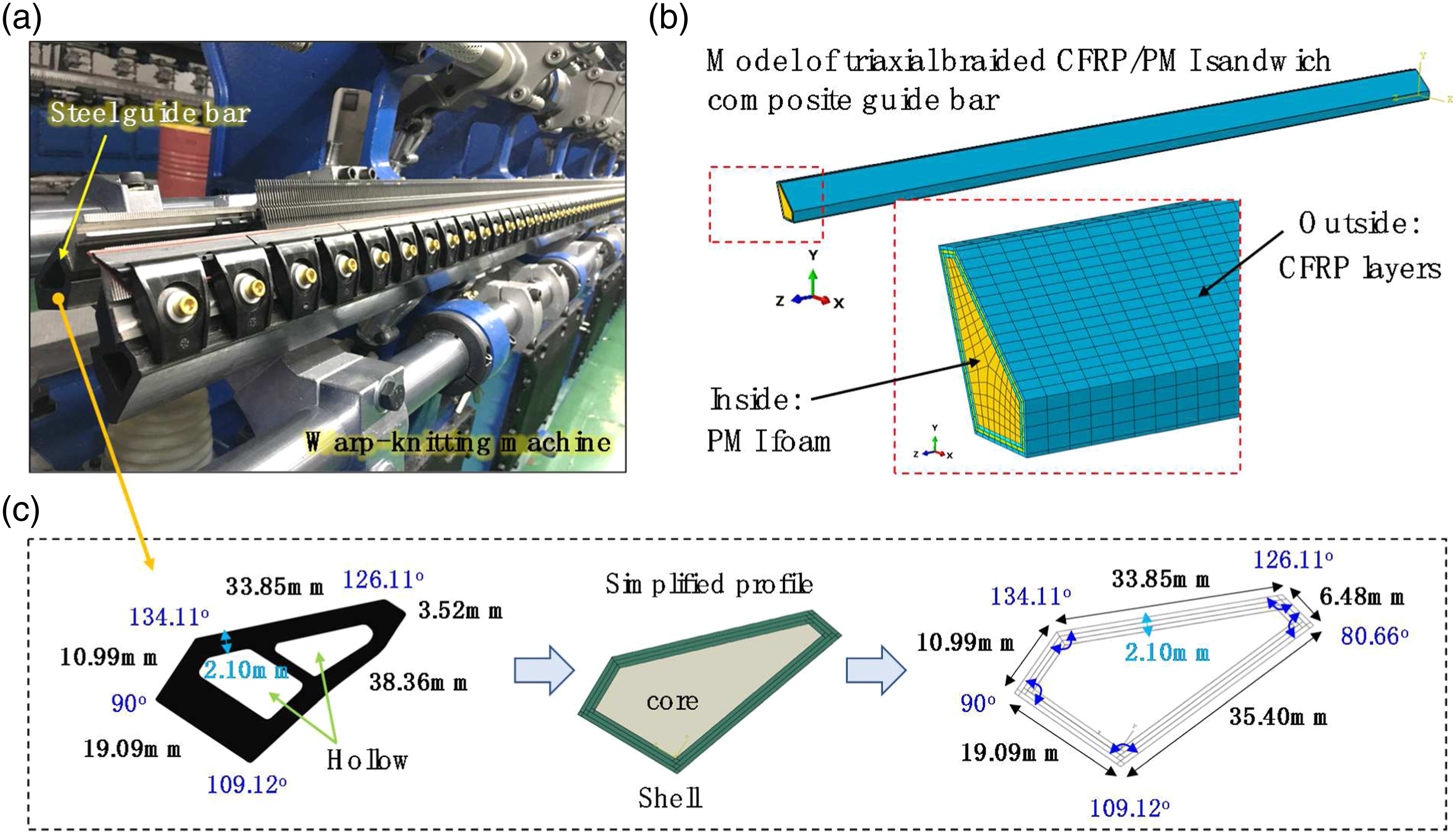
Basic parameters of the carbon fiber tows used for braiding the triaxial fabrics.

Mechanical properties of the PMI foam used for the core mandrel.


(a) The over-braiding machine and robot arm; (b) fabrication of a triaxial braided fabric by adjusting the extraction speed of the PMI foam mandrel controlled by the robot arm; (c) the prepared TBSC guide bar with a typical fiber orientation configuration [+45/0/-45]3; (d) cross-section view of the prepared TBSC guide bar.
Basic parameters of the epoxy resin used for the VARTM process.

Parameters of the prepared TBSC guide bar.

Analysis and discussion
Axial compression performance
As a composite bar, it is necessary to evaluate its axial mechanical properties and failure features. The axial compression behaviors of the TBSC guide bar specimens with different lengths were carried out in Figure 3. According to the actual test experience and existing literatures,23–28 the specimen length has a certain influence on its axial compression performance, that is, the so-called size effect. Therefore, specimens with different lengths (23 mm, 45 mm, and 92 mm) were prepared for tests. The axial compression rate was 2 mm/min for specimens. The infrared camera (FLIR X6530s) captured the progressive failure progress and indicated that the crash was from one end of the specimens. From Figure 4, it was observed that the progressive compression folding and limited eversion of the outer braided CFRP layers, and crushing and compaction of the internal PMI foam core. In the axial crushing process, typical damages of bulge and crease were found at the braided CFRP layers. There were no progressive splaying or outward fronds failure mode29–37 which were commonly occurred in the wound or other textile composite columnar structures. Therefore, the proposed triaxial braided sandwich composite guide bar has a reliable compression process under extreme axial crushing load, which is suitable for machine components. Axial compression load-displacement behavior and the IR images during the progressive failure process of the TBSC guide bar specimens with different length. Axial compression damage modes of the TBSC guide bar specimen.

Three-point bending performance
It is important to avoid any secondary disasters caused by bending fracture of machine components. For the TBSC guide bar, the three-point bending tests were carried out in Figure 5 by an electronic universal testing machine. According to the ASTM-D7264 standard, the ratio of span to the thickness of the three-point bending specimen is required to be at least 16:1. It was not easy to determine the span of the guide bar specimen due to its irregular cross-section. Image processing was used to obtain the cross-section of the composite guide bar. A scale was established to obtain the number of pixels per unit area. Since the total length of 118 pixels was 1 cm, one square centimeter contains 13924 pixels. There were 79129 pixels in the cross-section of the guide bar; thus, the cross-section was calculated as 5.6829 cm2. Then, according to the actual irregular cross-sectional area of the guide bar, an equivalent rectangle under the same width was obtained, with the equivalent thickness of 1.2685 cm. Therefore the span set in this study should be at least 20.296 cm (25 cm was finally set). Considering the appropriate length extended from both ends of the fixture, 37 cm was determined as the length of the sample. The indenter moving rate was 0.5 mm/min and the moving distance of the indenter was larger than 70 mm. Three-point bending load-displacement behavior and the IR images during the progressive failure process of the TBSC guide bar specimen.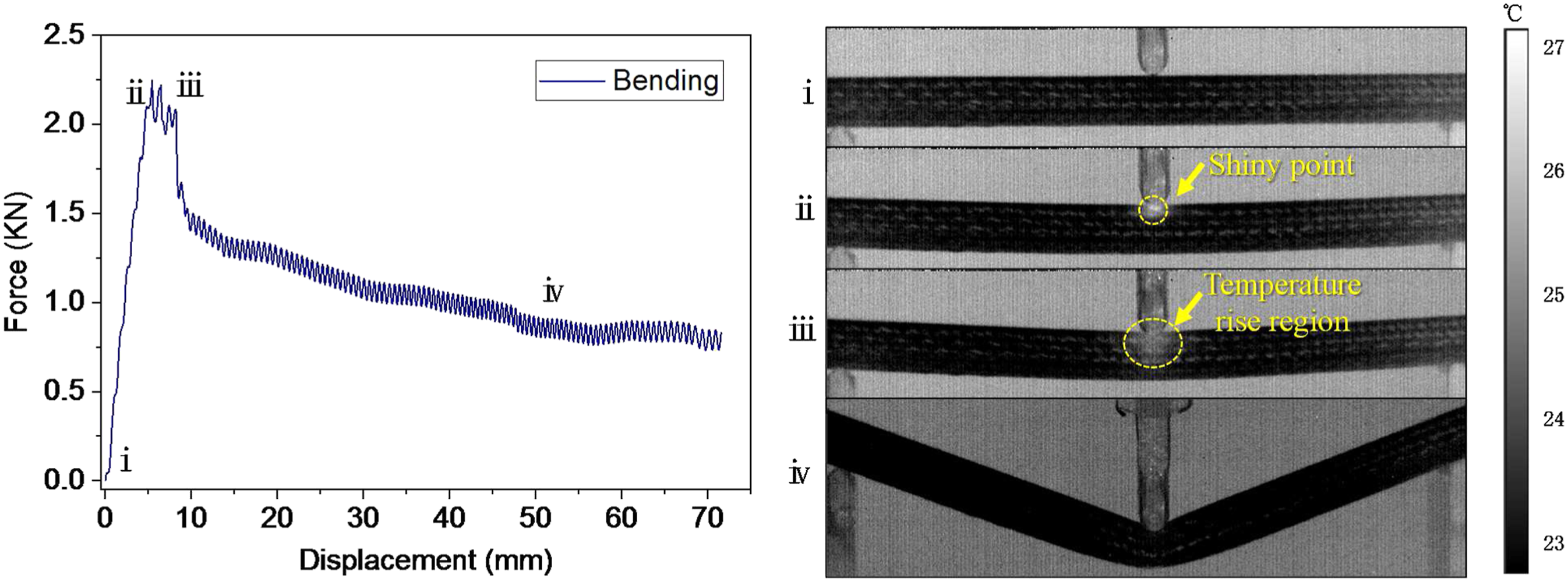
As shown in the stage i of Figure 5, a shiny point was found under the indenter which indicated the abrupt resin and yarns damages at compression stress state of the outer braided composite layers, which was proved by the damage at the upper-side of the guide bar specimen in Figure 6. From the stages ii to iii of Figure 5, few temperature-rise phenomena revealed that there were no abrupt damages because the bottom of the triaxial braided composite outer layers could withstand enough tensile stress during the stable bending state of the specimen, which was proved by the intact structure at the bottom-side of the guide bar specimen in Figure 6. In contrast, for biaxial braided composite columnar structures, CFRP fracture caused by tensile stress could be found at the bottom of composites22,38-40 during bending states. Therefore, the proposed triaxial braided sandwich composite guide bar has a stable deformation process under transverse loads, and will not have a catastrophic fracture. Three-point bending damages of the TBSC guide bar specimen.
Vibration performance
Vibration is the basic working condition characteristic of the guide bar when the warp-knitted machine is running. Therefore, it is of great significance to understand the natural frequency and vibration modes of the guide bar for its practical application. Since the operation speed of a high-speed warp knitting machine was generally not higher than 3,500 r/min, the natural frequency characteristics of composite guide bar within a certain effective range were mainly considered below. In this work, the natural frequencies and modal shapes of the TBCS guide bar under free and constrained boundary conditions were calculated by establishing the finite element simulation model.
Finite element model
As displayed in Figure 7(a), a full-scale guide bar model was established based on its real size. The simplified model was applied for the triaxial braided composite guide bar based on the following reasons: (1) Although the braided yarns are not ideally straight in composites, the classical simplified model (fiber inclination model41–43) has confirmed that the mechanical properties of complex textile composites could be approximately calculated by using laminates with different yarn orientation angles; (2) To facilitate parameter analysis, the braiding angle needs to be frequently adjusted in the design process. It inevitably requires a convenient simplified model to realize parametric input; (3) The vibration test in this work only involved the elastic characteristics of materials and structures. It did not need to consider the large deformation and failure of braided structures; and (4) Based on the idea of rapid design of engineering components, if a strictly precise model was adopted, the constitutive equation needed to be frequently established after the braiding parameters were changed. It would increase a lot of time consumption on programming. For the above reasons, considering the practical design needs at the start-up stage, three layers of unidirectional laminate with different orientation angles were used to approximately calculate a triaxial braided composite layer. The finite element model of the TBSC guide bar: (a) mesh scheme; (b) material model of one-layer triaxial braided CFRP; (c) two cases (free and constrained states) of the TBCS guide bar model.
The triaxial braided CFRP layers outside were meshed with 30000 SC8R (8-node quadrilateral in-plane general-purpose continuum shell, reduced integration with hourglass control) elements, while the PMI foam core inside was meshed with 7900 C3D8R (8-node linear brick, reduced integration, and hourglass control) elements.


Elastic properties of the PMI foam used in the model.


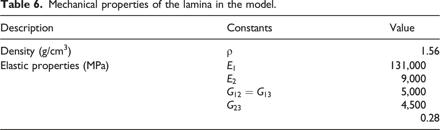
Mechanical properties of the lamina in the model.
For the boundary conditions, as illustrated in Figure 7(c), two cases (free and constrained states) of the TBCS guide bar were established according to whether there were fixed as the guide bar installed in the warp-knitted machine. Especially, for the constrained boundary conditions, two rigid shell fixtures were established (U1=U2=U3=UR1=UR2=UR3=0) in the model, at the position of 1/4 and 3/4 length of the bar respectively.
Free vibration analysis
Modes are the natural vibration characteristics of structures, and each mode has a specific natural frequency, damping ratio, and modal shape. During modal analysis, the free vibration equation of composite columnar beam structure based on finite element method can be written as:
The solution of equation (11) reflects the natural characteristics of the structure—natural frequency and vibration mode. Since the damping has little effect on the natural frequency and mode of vibration, equation (11) can be rewritten as the generalized eigenvalue equation in the following form
Compared with the steel hollow guide bar structure, the TBSC structure has its advantage on the vibration frequency. As illustrated in Figures 8 and 9, the natural frequency of [+45/0/-45]3 TBSC guide bar and steel hollow guide bar were close under the mode order 1 and 2. For example, in order 2, the frequency of the TBSC guide bar was 300.98 Hz while the steel guide bar was 288.64 Hz, and they have similar bending behavior. However, when the order was higher than 2, the natural frequency of [+45/0/-45]3 TBSC guide bar was significantly improved. For example, at order 3, the frequency of the TBSC guide bar was 391.27 Hz while the steel guide bar was 338.03 Hz; at order 6, the frequency of the TBSC guide bar increased to 1206.20 Hz, while the steel guide bar was still at the low 640.10 Hz. Relatively high vibration frequency is a necessary factor to make the TBSC guide bar structure has better dynamic performance under complex tremor working conditions. Comparison of vibration characteristics between the TBSC guide bar ([+45/0/-45]3) and traditional steel hollow guide bar at free vibration state. (Deformation amplification factor 50). Comparison of vibration characteristics between the TBSC guide bar ([+45/0/-45]3) and traditional steel hollow guide bar at free vibration state.

Besides, as shown in Figure 8. Mode order seven could be the first torsion for the TBSC guide bar, while order 4 was seen the first obvious periodic torsion expansion and collapse for the steel guide bar. For the steel guide bar, axial periodic torsion collapse and severe cross-section distortion were found at orders 4, 5, 6, and 8. For the TBSC guide bar, transverse bending was the main vibration deformation state at the corresponding order 4, 5, 6, and 8. The comparison indicates that the cross-section of the TBSC guide bar could keep its shape with the increase of the mode order, while the steel hollow guide bar was seen the obvious excessive local structure and shape distortion of cross-section under high-order modes (when the order was larger than 3). Therefore, the TBSC guide bar displayed a better ability to avoid excessive local structural distortion with higher-order modes.
Validation of the finite element model
Experimental modal analysis was carried out to test the validity of the numerical method by finite element simulation. To simplify the test scheme, the free vibration scheme was applied to validate the FE model. In other words, if the finite element calculation results of free vibration are close to the experimental results of free vibration, the model established should be credible. Then we can predict the vibration characteristics under various other working conditions by changing the model design or constraints, to greatly reduce the cost of guide bar design.
The vibration test equipment includes acceleration sensors (PCB 356A16), impact hammer (PCB 086C03; Mass 0.16 kg; Sensitivity 2.25 mV/N; Frequency range 8 kHz; Force range: ± 2224 N), data acquisition and analysis system (AVANT MI-7008), and computer. To make the guide bar as free as possible, the installation method of rope suspension was adopted, as shown in Figure 10(a) and (b). The middle of the bar was selected as the knocking point. It is required to hammer in the same direction and at the same position each time. The motivation should be consistent as far as possible to avoid secondary combos. Eight test points were set on the bar by adopting the principle of uniform distribution as depicted in Figure 10(d). The data of five repeated experiments were collected at each sensor location (Figure 10(c) and (d)), and the average value of 5 times was finally taken as the required data from each signal acquisition position. (a) Layout of free vibration test of the TBSC guide bar ([+45/0/-45]3); (b) local view of one end of the testing bar; (c) tight contact between the acceleration sensor and the specimen; (d) schematic diagram of sensor location and signal acquisition.
Comparison between free vibration test and FEM simulation results.

The main reasons for the difference between finite element simulation analysis and modal test results are analyzed: (1) the material orientation in the finite element model was equivalent to laminated plates with different angles, which is different from the real situation of yarn fluctuation in the braided structure; (2) In the experimental modal test, the installation mode of the object to be tested suspended by rope was only an approximate free state, which was different from the ideal free state without any constraints used in the finite element analysis; (3) In a certain frequency range, the order number of natural frequencies obtained by finite element analysis was more than that obtained by modal test; The absent experimental data at mode order 3 and 11 were due to limited test points and sensors arranged on the guide bar (only the natural frequencies of the main modes of the structure could be obtained, and some secondary modes were difficult to collect by data acquisition system).
In general, the comparative analysis between the finite element simulation and experimental modal test results shows that the average relative error of the natural frequency of the simulation and test was 8.06%, and the results were relatively consistent. The FE model established in this work can truly reflect the vibration characteristics of the CFRP/PMI sandwich composite guide bar and will be suitable for further analysis under other working conditions.
Constraint boundary (actual working condition)
Under actual working conditions, as displayed in Figure 1(a), the TBSC guide bar will be fixed on the machine fixtures with certain spacing. Therefore, the study of constrained boundary conditions (as shown in Figure 7(c)) has more practical significance. We calculated and analyzed the TBSC guide bar through the above finite element model, and obtained the following clues:
Based on the calculation results in Figure 11, the range of vibration deformation of the [+45/0/-45]3 TBSC guide bar under the constrained state was much more limited than that at the free vibration state. The bending deformation was either localized at one end of the guide bar asymmetrically (at the order 1, 2, 4, 5, and 8), or symmetrically (at the order 3, 6) and antisymmetric (at the order 7) in the middle of the guide bar. These bending deformation under the constrained state were all less than 1/3 length of the whole bar. It is the inherent characteristic of the TBSC structure under specific constraints and vibration modes. Due to the restraint of the fixtures, the whole guide bar was separated into three sections as shown in Figure 7(c). Under the blocking action of the fixtures, the localized deformation could not propagate among the three sections, which were only limited in their respective sections. While the guide bar at the free vibration state presented a global symmetric (at the order 1, 2, 4, and 8) or global antisymmetric (at the order 3, 4, 5, 6, and 7) deformation morphology, because the vibration deformation could propagate along the whole guide bar without fixtures. Comparison of vibration mode of the TBSC guide bar ([+45/0/-45]3) at (a) free vibration state or (b) under constraint. (Deformation amplification factor 50).
In Figure 12, with the increase of the order number, it is found that the frequency of the [+45/0/-45]3 TBSC guide bar under constraint boundary condition had a similar increasing tendency to that at free vibration. Generally, within the order number from 1 to 14, the guide bar under constraint boundary conditions had higher frequency values. For example, at the mode order 1, 2, 3, 7, 8, 9, 10, 11, and 12, the vibration frequency under constraint was seen 255.04 Hz, 98.18 Hz, 219.43 Hz, 333.20 Hz, 512.30 Hz, 351.10 Hz, 311.50 Hz, 183.30 Hz, and 181.10 Hz larger than those at the corresponding orders under free vibration state. Therefore, in most cases, the TBSC guide bar installed on the machine will have a better resistance performance on the vibration and high-frequency resonance than at the free state. Comparison of vibration frequency of the TBSC guide bar ([+45/0/-45]3) at free vibration state or under constraint.
Meanwhile, it is also obtained that the frequency of the TBSC guide bar under constraint was very close (order number 5, 6, and 14) or even a few lower (order number 13) than that at free vibration state, which might be related to the braiding angle in the TBSC guide bar. Therefore, it was necessary to investigate whether and how the braiding angle configurations had something to do with the frequency characteristics.
As shown in Figure 13, the TBSC guide bar model with different triaxial braided configurations was established in the finite element model by changing the laying ply angles. It is found that the guide bar with different braiding angles presented a similar deformation either localized at one end of the guide bar or in the middle of the guide bar. But at certain mode orders, the large-angle (60o and 75o) braided structures behaved an opposite-side deformation compared with the small-angle (15o and 30o) braided structures. For example, when at the mode order 7, 8, and 9, the [+60/0/-60]3 and [+75/0/-75]3 TBSC guide bars displayed the deformation at the other end of the bar compared with the [+15/0/-15]3 and [+30/0/-30]3 counterparts. Therefore, the effect of braiding angle was seen as significant on the deformation morphology at some mode orders. Comparison of constraint vibration characteristics of the TBSC guide bar having different braiding angle configurations. (Deformation amplification factor 50).
Furthermore, the braiding angle reveals its significant effect on the frequency-order response and deformed displacement field of the TBSC guide bar. As exhibited in Figure 14(a), the increase of braiding angle had a negative effect on the frequency at the low order 1–6. But such tendency changed at higher-order from 7 to 14, where the frequency of [+15/0/-15]3 and [+75/0/-75]3 TBSC guide bars were much lower than that of [+30/0/-30]3 and [+45/0/-45]3 counterparts. It could be due to the difference in their anti-torsion ability. For example, the torsional deformation was found at the order 8, 9, and 10 in Figure 13. But the braiding configuration [+15/0/-15]3 and [+75/0/-75]3 were both not good at the anti-torsion ability, because there were larger differences between the orientation angle of their braiding yarns and the ±45° angle that mainly resists the circumferential shear force caused by the torsional bar. While the [+30/0/-30]3, [+45/0/-45]3, and [+45/0/-45]3 counterparts could have a better anti-torsion ability, because their braiding yarns were more conducive to the performance of resisting circumferential shear force when the bar was twisted. When the magnitude of the maximum deformed displacement was further considered, as reflected in Figure 14(b), the [+45/0/-45]3 configuration presented the most stable vibration deformation with lower amplitude, especially when the mode order was from 7 to 14. These results indicate that, if both the frequency-order response and maximum deformed displacement were important in the design of the TBSC guide bar, the scheme [+45/0/-45]3 of the outside braided composite may be comprehensively the best. Comparison of vibration frequency of the TBSC guide bar having different braiding angle configurations under constraint: (a) frequency-order relation; (b) Umax-order relation.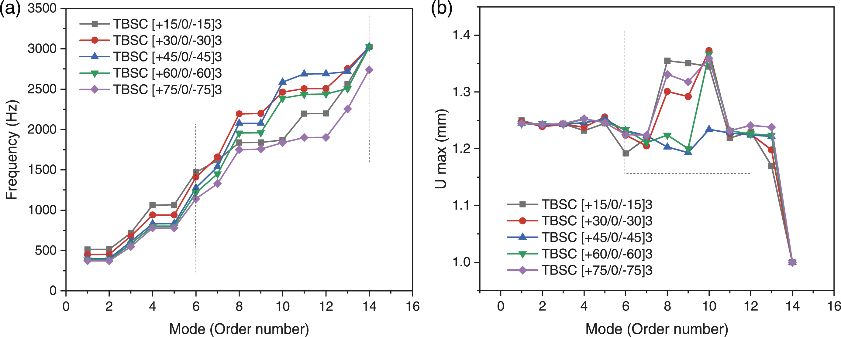
As supplementary notes, the precautions for surface flatness and subsequent installation and use of the composite guide bar are suggested: (1) The inner wall surfaces of the VARTM mold should be smooth and accurate to ensure the flatness in the curing process of composite; (2) The spraying of release grease on the inner wall surfaces of mold shall be uniform and consistent in thickness; (3) In the demolding process of the composite after curing, the bending and torsional forces should be avoided as much as possible; (4) During the installation process, clamping parts should be ensured that they have uniform pressure on each surface of the special-shaped composite guide bar. Because resin fragmentation may be caused by stress concentration on some irregular corners of the composite guide bar; and (5) Carbon fiber composites are rigid but brittle, and their out-of-plane mechanical properties are relatively lower than those along the axial direction. Therefore, tool collision from transverse and lateral should be avoided as far as possible in the process of component installation and use.
In addition, there are still several aspects worthy of continuous improvement in the future: (1) carbon fiber tows with different linear densities can be used as braided yarns and axial yarns; (2) The ratio of CFRP layers and PMI mandrel can be adjusted to better match the performance requirements of guide bar; (3) Further in-suit vibration test and analysis can be carried out after the guide bar is installed on the machine; and (4) More accurate simplified models need to be developed for rapid analysis by mechanical design engineers. It is hoped that this paper can provide a feasible reference scheme and preliminary exploration for the lightweight design of key components in a high-speed warp knitting machine.
Conclusion
Integrated manufacturing technology was applied to fabricate the 3-D triaxial braided CFRP/PMI sandwich composite guide bar based on the geometric requirements of real components. The axial compression, three-point bending, and vibration performance of the bar specimens were investigated. Furthermore, the natural frequencies and vibration modes of the TBSC guide bar at free and constraint conditions were obtained by the numerical model, and the parametric analysis of different braiding angles was carried out. The conclusions are summarized as follows: The effectiveness of the proposed full-scale finite element model is verified by vibration experiments. The classical approach (fiber inclination model) was applied to establish the complex triaxial braided composite structure using laminates with different orientation angles. It facilitated parameter analysis for considering the braiding angle adjustment. The vibration experiments in this work only involved the elastic characteristics of materials and structures, which could be corresponded by the stiffness matrix in elastic constitutive of the simplified model. The TBSC structure has its advantage on the vibration frequency. The natural frequency of the TBSC guide bar and steel hollow guide bar was close at order 1 and 2, and they have similar bending behavior. However, when the order was higher than 2, the frequency of the TBSC guide bar was significantly improved. Therefore, the relatively high vibration frequency is a necessary factor to make the TBSC guide bar has better dynamic performance under complex tremor working conditions. The TBSC guide bar displayed a better ability to avoid excessive local structural distortion with higher-order modes. For the steel guide bar, axial periodic torsion collapse and severe cross-section distortion were found at orders 4, 5, 6, and 8. For the TBSC guide bar, transverse bending was the main vibration deformation state at the corresponding order 4, 5, 6, and 8. Therefore, for the consideration of section stability when the order is larger than 3, the TBSC guide bar will be a good choice because it could keep its shape with the increase of the mode order. The range of vibration deformation of the TBSC guide bar under the constrained state was much more limited than that at the free vibration state. The bending deformation was either localized at one end of the guide bar or in the middle of the guide bar, less than 1/3 length of the whole bar. While the guide bar at the free vibration state presented a global deformation morphology. With the increase of the order number, the frequency of the TBSC guide bar under constraint had a similar increasing tendency to that at free vibration. Generally, the guide bar under constraint had higher frequency values. At the mode order 1, 2, 3, 7, 8, 9, 10, 11, and 12, the vibration frequency under constraint was seen 255.04 Hz, 98.18 Hz, 219.43 Hz, 333.20 Hz, 512.30 Hz, 351.10 Hz, 311.50 Hz, 183.30 Hz, and 181.10 Hz larger than those in a free state. Therefore, in most cases, the TBSC guide bar installed on the machine will have a better resistance performance on the vibration and high-frequency resonance than in the free state. The effect of braiding angle was seen as significant on the deformation morphology. At certain mode orders, the large-angle (60o and 75o) braided structures behaved in reverse deformation directions compared with the small-angle (15o and 30o) braided structures. The [+60/0/-60]3 and [+75/0/-75]3 TBSC guide bars displayed the localized deformation at the opposite end to the [+15/0/-15]3 and [+30/0/-30]3 counterparts at the mode order 7, 8, and 9. Furthermore, the increase of braiding angle had a negative effect on the frequency at the low order 1–6. But such tendency changed at higher-order from 7 to 14. The frequency of [+15/0/-15]3 and [+75/0/-75]3 TBSC guide bars were much lower than that of [+30/0/-30]3 and [+45/0/-45]3 counterparts. If the maximum deformed displacement is considered, the [+45/0/-45]3 configuration will be the best choice, especially when the mode order is from 6 to 12.
Footnotes
Declaration of conflicting interests
The author(s) declared no potential conflicts of interest with respect to the research, authorship, and/or publication of this article.
Funding
The author(s) disclosed receipt of the following financial support for the research, authorship, and/or publication of this article: This work was supported by the National Natural Science Foundation of China (52075498, 11702249); Zhejiang Provincial Natural Science Foundation of China (LGG19E050028).