
Abstract
Highly integrated, low-cost and multi-functional electronic data gloves have attracted extensive attention in the Age of the Internet of Things. While significant progress has been made in the design of strain sensors with wide strain ranges, it is challenging to integrate high linearity, broad strain sensing range, and fast response into a single type of strain sensor, and these sensing properties play a critical role in the development of high-performance data gloves. Herein, this study presents a highly flexible, stretchable, and sensitive silver nanoparticles/double covered yarn (AgNPs/DCY) composite yarn, and this yarn as strain sensor achieves broad strain sensing range (50%), ultralow detection limit (0.05%), high linear sensitivity (GF = 10), instant response time (24 ms) and high repeatability, simultaneously. Interestingly, the AgNPs of the AgNPs/DCY composite yarns fabricated by in situ reduction are observed to not only evenly distributed on the fiber surface of DCY, but also within core fiber, and this distribution and the DCY structure; that is, the cooperative sensing effect of microcrack propagation of conductive layer on fibers and the electrical contact resistance contributes to the good sensing performance. Additionally, this composite yarn as strain sensor is invisibly integrated into textile data gloves and the capability of real-time monitoring various finger motions and effectively recognizing sign languages demonstrates the good sensing performance and practicability of the developed composite yarn. Therefore, the composite yarn as strain sensor has great prospects in wearable electronics.
Introduction
Wearable electronic products with flexibility, portability, and large deformation have great potential in various applications such as medical monitoring system, electronic skin, and human-computer interaction, and they are becoming suitable candidates for the next generation of electronic devices.1–4 In these emerging applications, data gloves widely used in human-computer interaction, virtual reality, and gesture recognition, require strain sensors with a wide strain sensing range, because hand movements are within the strain range of about 50%.5–7 In recent years, many efforts have been devoted to highly stretchable and sensitive strain sensors by the combination of various conductive materials with different stretchable substrates (e.g., film,8–10 fabric,11,12 yarn13,14). Compared with other strain sensors, fiber-based or yarn-based sensors not only have the characteristics of softness and good stretchability, but also are more flexibly attached to the human body for precise monitoring in one direction. In addition, they are easily integrated into a variety of complex textile or cloth through advanced textile technology (such as weaving, knitting, braiding) to achieve truly the integration of clothing and electronics and meet the requirements of the beauty and comfort of wearing. As a result, sensing fibers or yarns are more suitable for developing a new generation of flexible strain sensors.3,15
Generally, there are two major methods to fabricate fiber-based or yarn-based strain sensors. One is to make conductive fibers through various spinning techniques such as melt spinning, wet spinning, or electrospinning. Zhang et al. 16 reported that multi-wall carbon nanotubes/silver nanowires thermoplastic polyurethane (AgNWs/MWCNT/TPU) composite fibers with high conductivity were prepared by wet spinning process. MWCNTs and TPU fibers were used as active sensing element and elastic support substrate respectively, and AgNWs was used to improve the conductivity of strain sensors. When the content of AgNWs reaches the optimum content (3%), the strain sensor shows wide working strain range (254%) and excellent electrical conductivity (0.0803 S/cm). Seyedin et al. 17 designed coaxial conductive fiber consisting of MXene/polyurethane (PU) composite material as sheath and PU as core by coaxial wet spinning method. This kind of strain sensor exhibits great improvements in working strain range and cyclic stability compared to non-coaxial composite fiber. The other is to coat or grow the conductive layer on the surface of the fiber or yarn by dip-coating, in situ chemical polymerization, layer by layer assembly method, etc. For example, Zhu et al. 18 fabricated a PU/AgNWs fiber-based strain sensor by capillary glass tube (CGT)coating to make AgNWs embed on the surface of PU fiber. The PU/AgNWs fiber not only shows good conductivity (3.1 S/cm) and large elongation at break (265%), but also has high gauge factor (87.6 at 22% strain), short response time (49 ms). Gong et al. 19 reported a flexible abrasion-proof spandex composite yarn with a laminated coating by alternating dips of MXene and polydopamine. The strain sensor has high sensitivity (GF = 5.7×10⁴), low detection limit (0.11%), and wide sensing range (0.11–61.2%), which can accurately monitor large-scale and small-scale biological activities of human body. These methods can be used to manufacture fiber-based or yarn-based strain sensors with good fatigue properties and remarkable tensile properties. However, the electrical responses of the above-mentioned resistance-type strain sensors are mostly highly nonlinear, so that the acquired data are difficult to process and analyze. 20 Additionally, the response time is a critical performance parameter of the strain sensor under dynamic strain. If the response time of the strain sensor is too long, it is not suitable for real-time application scenarios. 21 For human motion monitoring, on the premise that a large range of deformation (50% strain) can be achieved, the detection limit of the strain sensor should be further reduced to meet the monitoring and observation of small strain. However, it is still a challenge to achieve a good combination of high linearity, fast response, and low detection limit in a textile strain sensor with good stretchable and structural stability.
In this work, we report a kind of AgNPs/DCY composite yarn strain sensor with excellent linearity, ultralow detection limit, and rapid response, which is easily integrated into textile by advanced textile technology. By in situ chemical reduction, the PET double wrapped filaments are deposited with silver nanoparticles (AgNPs), and even the core elastic rubber fiber is made into a conductive composite fiber with AgNPs conductive sheath. This composite structure results in a mixed sensing mechanism, namely crack propagation and change of conductive contact areas. To characterize performances of the yarn-based strain sensor, we study the morphological structure, mechanical and sensing property, including working strain range, lower detection limit, sensitivity, response time, and repeatability. For practical applications, the AgNPs/DCY composite yarn as strain sensor is integrated into an electronic data glove to evaluate its capability in gesture recognition.
Experimental section
Materials
Silver trifluoroacetic acid (STA) (AgCF3COO, 98% purity) was purchased from Shanghai Bide Medical Technology Co., Ltd. Ethanol (CH3CH2OH, purity ≥99.7%) was supplied by Sinophenol Chemical Reagent Co., Ltd. Hydrazine hydrate (N2H4·H2O, 80% aqueous solution) was acquired from Shanghai Taitan Technology Co., Ltd. Double covered yarn (DCY) (fineness of rubber core fiber: 1600D, polyester wrapping filaments: 200D*2) was sourced from commercial yarns.
Preparation of AgNPs/DCY strain sensor
Figure 1(a) illustrates the fabrication procedure of AgNPs/DCY composite yarns. First, the DCY was cleaned via mild sonication in deionized (DI) water and ethanol for 10 min and then dried in the air. Afterward, the cleaned DCY was dipped into solution A mixed with 30 wt% STA and 70 wt% ethanol for 30 min to absorb the silver precursors. Due to the ionic dipole interaction between the trifluoroacetate anions (CF3COO–) and the hydroxyl groups (–OH) of the alcohol solvent, the trifluoroacetate anions are easily absorbed by original yarn. With the swelling of DCY, the selection of low molecular weight ethanol solvent makes silver ions penetrate deeper into the elastic core fiber. It was then dried in an oven (65°C) for 5 min and the solvent was evaporated from the yarn. The solution B consisting of 1:1 (V/V) hydrazine hydrate and ethanol was prepared as the reducing agent. After the yarn was impregnated in solution B for 5 min, the previously adsorbed Ag ions were reduced to form AgNPs. Finally, the yarn was cleaned three times with DI to remove the residual hydrazine hydrate, and then the yarn was dried at 65°C for 30 min. Compared with the original white DCY (Figure 1(b)), the AgNPs/DCY composite yarn turned yellow, indicating that AgNPs were successfully deposited on the surface of DCY. Based on the number of cycles the above procedure is repeated, the treated yarns are named r-x, where x represents the reduction times. For example, the original yarn DCY is named r-0, and the firstly reduced yarn is named r-1. The two ends of 60 mm composite yarn are wound with copper wire, respectively, and the interconnected parts are fixed with conductive glue. Finally, the sensing yarn with an effective stretching length of 50 mm is made successfully. (a) Schematic illustration of the fabrication procedure for the AgNPs/DCY composite yarns. (b) Optical images of the DCY and AgNPs/DCY composite yarn. The scale bar is 1 mm. (c) Schematic structure of AgNPs/DCY composite yarn after stretching.
Measurements and characterizations
Field emission scanning electron microscope (S-4800, Hitachi High-tech Corporation, Japan) was used to observe the surface and cross-section microstructure and morphology of original DCY and AgNPs/DCY composite yarn. The SEM observation of the gold-plated samples was carried out with a secondary electron detector at an accelerating voltage of 10 kV. Scanning electron microscopy (FlexSEM1000, Hitachi High-tech Company) was utilized to observe the structure of AgNPs/DCY sensing yarn under different strains. In order to study the mechanical and electrical properties of composite yarn, the breaking strength and breaking elongation of composite yarns were tested by universal material testing machine (Zwick, Z050) according to GB/T 3916-2013. Spandex strength stretch elasticity tester (XN-1A, Shanghai New Fiber Instrument Co., LTD) was applied to test the elastic recovery rate of yarns by constant elongation cycle method at 100% strain according to FZ/T 50007-2012. Agilent 34970A was used to measure the resistance of each group of yarns. The sensing yarns were fixed with the isolation clip of the tensile testing machine to maintain different strain states, and then the Keithley 6487 Pico ammeter was connected to record the voltage and current data of the sensing yarns under different strain states.
To analyze the sensing performance of the sensing yarn, the universal material testing machine was used to clamp and stretch samples. Considering the length embedded into glove, the test length of the sensing yarn was set to 50 mm. The universal material testing machine was used in combination with Agilent 34970A to record the strain and resistance of the sensing yarn during the stretching process. Each sample underwent 20 pre-stretching and release cycles prior to the strain sensing test. In the pre-stretching process, the larger the strain applied, the more the resistance increases and the more fragile the conductive network, and therefore the greater the sensitivity. The propagation of different cracks can be controlled by different pre-stretching coefficients and different pre-stretching velocities, and results in different sensitivity of sensing yarns.22,23 Here, the pre-stretching coefficient of 50% and the stretching speed of 100 mm/min were selected through the pre-experimental samples.
The gauge factor (GF) of the strain sensor is calculated by the following equation

Results and discussion
Morphology and electrical properties of AgNPs/DCY composite yarn
Figure 2 shows the surface and cross-section morphology of the original DCY and AgNPs/DCY composite yarn. The diameter of DCY was 639±19 μm, and the surface of PET filament was very smooth (Figures 2(a) and (b)). After silver nanoparticles were deposited on DCY by in situ chemical reduction, in Figures 2(c) and (d) the surface of the original yarn displays a dense film of AgNPs, and the diameter of the AgNPs/DCY composite yarn was 679±15 μm. In addition, the surface of the AgNPs/DCY composite yarn became rough (Figures 2(d) and (e)), and the dense arrangement of silver nanoparticles with the diameter around 175 nm was clearly observed. These demonstrated that AgNPs were coated on DCY surface by chemical reduction method successfully. Next, the AgNPs/DCY composite yarn was fractured in liquid nitrogen to observe the cross-section. As shown in Figures 2(g) and (h), besides two layers of PET multifilament loaded with AgNPs, a layer of AgNPs was gathered on the surface of rubber core fiber, and even a small amount of AgNPs was distributed inside the core fiber. In this sense, the rubber core fiber becomes AgNPs/rubber composite fiber. The silver precursor permeating the core fiber effectively generates a large number of Ag nanoparticles within the fiber, resulting in good electrical connections between all Ag nanoparticles, so that the composite yarn has good electrical conductivity. On the other hand, the surface morphology of the core fiber was observed after peeling off the outer two layers of the AgNPs/DCY composite yarn. The conductive layer loaded on the outer layer of the core fiber formed microcracks in the radial direction after stretching (Figure 2(f)), which leads to the increase of resistance of the sensing yarn in the stretching process. (a, b) SEM images of the DCY surface at different magnification. (c–e) SEM images of the AgNPs/DCY composite yarn surface at different magnification. (f) SEM image of the core fiber surface of the AgNPs/DCY composite yarn. (g) SEM image of cross-section of the AgNPs/DCY composite yarn. (h) EDS mapping images of Ag obtained from the AgNPs/DCY composite yarn.
To optimize reduction times of the composite yarn, the electric properties of composite yarns with different reduction times were evaluated as shown in Figure 3. The initial resistance of the composite yarn decreased from 220.99 Ω/cm to 4.34 Ω/cm with the increase of silver ion absorption and reduction times from 1 to 4 (Figure 3(a)). The initial resistance of the yarn showed a descending tendency to relatively stable level with the increase of reduction times, while the AgNPs loading mass for each reduction was similar. Observably, the nanoparticles loaded on the yarn were close and uniform enough to form a good and stable conductive pathway after several reduction times. Given the good conductivity of r-4 composite yarns, they were selected as the samples for subsequent tests unless otherwise stated. The resistance of the AgNPs/DCY composite yarn linearly increased with the length (Figure 3(b)), which also means the even AgNPs depositions. Thus, the change of resistance of AgNPs/DCY composite yarn can be controlled by the thickness of the network of silver nanoparticles from different reduction times. At the same time, the composite yarn exhibited a linear current-voltage curve at different strain levels from 0 to 15% (Figure 3(c)), implying that it has good ohm characteristic behavior. (a) Initial resistance and mass per unit length of yarns with different reduction times. (b) Initial resistances of r-4 composite yarns at different unit lengths. (c) Current-voltage characteristic curves of r-4 composite yarns at different strains.
Mechanical performance of AgNPs/DCY composite yarn
Figure 4(a) displays the breaking strengths and elongations of samples with different reduction times. Figure 4(b) presents the compliance curves of the composite yarns with varying reduction times. In general, the tensile force and elongations decreased with the increase of reduction times. Before in situ chemical reduction treatment, the breaking strength and elongation of the original yarn were 9.420 N and 366%, respectively. After four reductions, the breaking strength and elongation of the composite yarn deteriorated to 6.521 N and 305%, respectively. The increase of the content of silver nanoparticles in the composite yarn and the treatment of reducing agent changed the mechanical properties of the yarn. Although the breaking strength and elongation decrease, the mechanical properties of the yarn still meet the requirements of knitting on the machine. It is worth noting that at around 200% tensile strain, the strength fluctuations start to appear and gradually increase. This is due to the fact that the inner and outer covered filaments straighten out, slip and break with an increasing strain. The PET filament breaks one after another until finally the elastic core fiber breaks, so that an observable fluctuation exists under large elongation. (a) Force and elongation of yarns with different reduction times. (b) Force-elongation curves for tensile tests on yarns with different reduction times. (c) Elastic recovery rates of yarns with different reduction times.
As shown in Figure 4(c), the elastic recovery rate of composite yarn fell by 6.13% with the increase of reduction times, from 95.54% of the original yarn to 89.68% of r-4 yarn. On the one hand, the elastic properties of composites largely depend on the number of nanoparticles embedded in the elastomers.24,25 On the other hand, the increase of the content of silver nanoparticles makes the fiber surface much rougher, and the friction coefficient between the PET filaments and the core fiber increases. After stretching and slipping, they cannot recover to the initial position due to the friction resistance. In this sense, if the yarn is permanently deformed after repeated stretching, the conduction path of the yarn will change and induce the resistance of yarns increase irreversibly, thus deteriorating the repeatability and stability of the yarn sensor.
Strain sensing performance of AgNPs/DCY composite yarn
To investigate the strain sensing properties of AgNPs/DCY composite yarns, different tensile tests were carried out. Considering that the finger movement deformation is less than 20 mm extension,
26
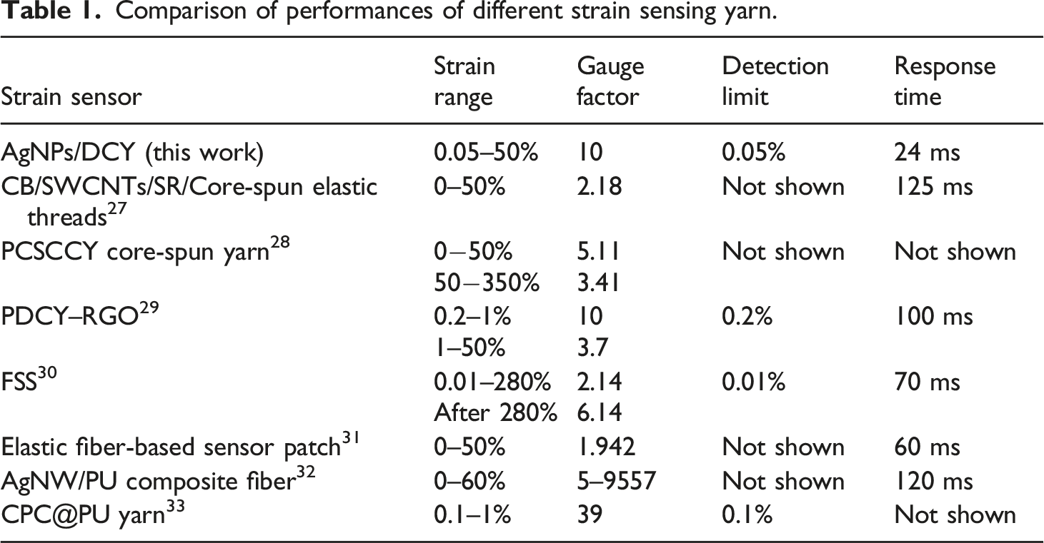
we focus on the sensing performance of the composite yarn within 50% strain. It noted that the relative resistance of the composite yarn exhibits a remarkable linear change within the 50% strain, and the fitting goodness is as high as 0.99 (Figure 5(a)). In the subsequent 20 repeated stretching, the linearity of the composite yarn decreases slightly, but it still remains above 0.96 (Figure 5(b)). Anyway, the linear GF of the sensing yarn is about 10 within 50% strain. The GF of some previously reported fiber-based or yarn-based flexible strain sensors is listed in Table 1. Compared with those yarn strain sensors with similar structure,27–31 the linear sensitivity of AgNPs/DCY sensing yarn is much higher. In order to determine the detection limit, the tensile strain is gradually weakened and the dynamic response was recorded. The result is shown in Figure 5(d). It can be observed that the minimum detection range of the composite yarn is 0.05% from Figure 5(e), and the linear GF within 50% strain reaches 2.53 or so. In this way, the composite yarn as strain sensor has the potential to monitor subtle changes in human movement and rehabilitation training. The relative resistance change of AgNPs/DCY yarn: (a) Under first stretching with 50% strain, the stretching speed is 120 mm/min. (b) After 20 stretches within 50% strain, the stretching speed is 120 mm/min. (c) 5 stretching-releasing cycles at strain levels of 10, 20, 30, 40, and 50%, the stretching speed is 120 mm/min. (d) 5 stretching-releasing cycles at strain levels of 5, 3, 1, 0.5, and 0.2%, the stretching speed is 30 mm/min. (e) Under repeated loading-unloading tests with 10 cycles at a small strain of 0.05%, the stretching speed is 30 mm/min. (f) 5 stretching-releasing cycles under 10% strain at the stretching frequency of 0.4, 0.8, and 1.2 Hz. (g) The rapid response under 1% strain at the stretching speed of 500, 300, and 100 mm/min. (h) The rapid response under 10, 5, and 1% strain respectively, at the stretching speed of 300 mm/min. Comparison of performances of different strain sensing yarn.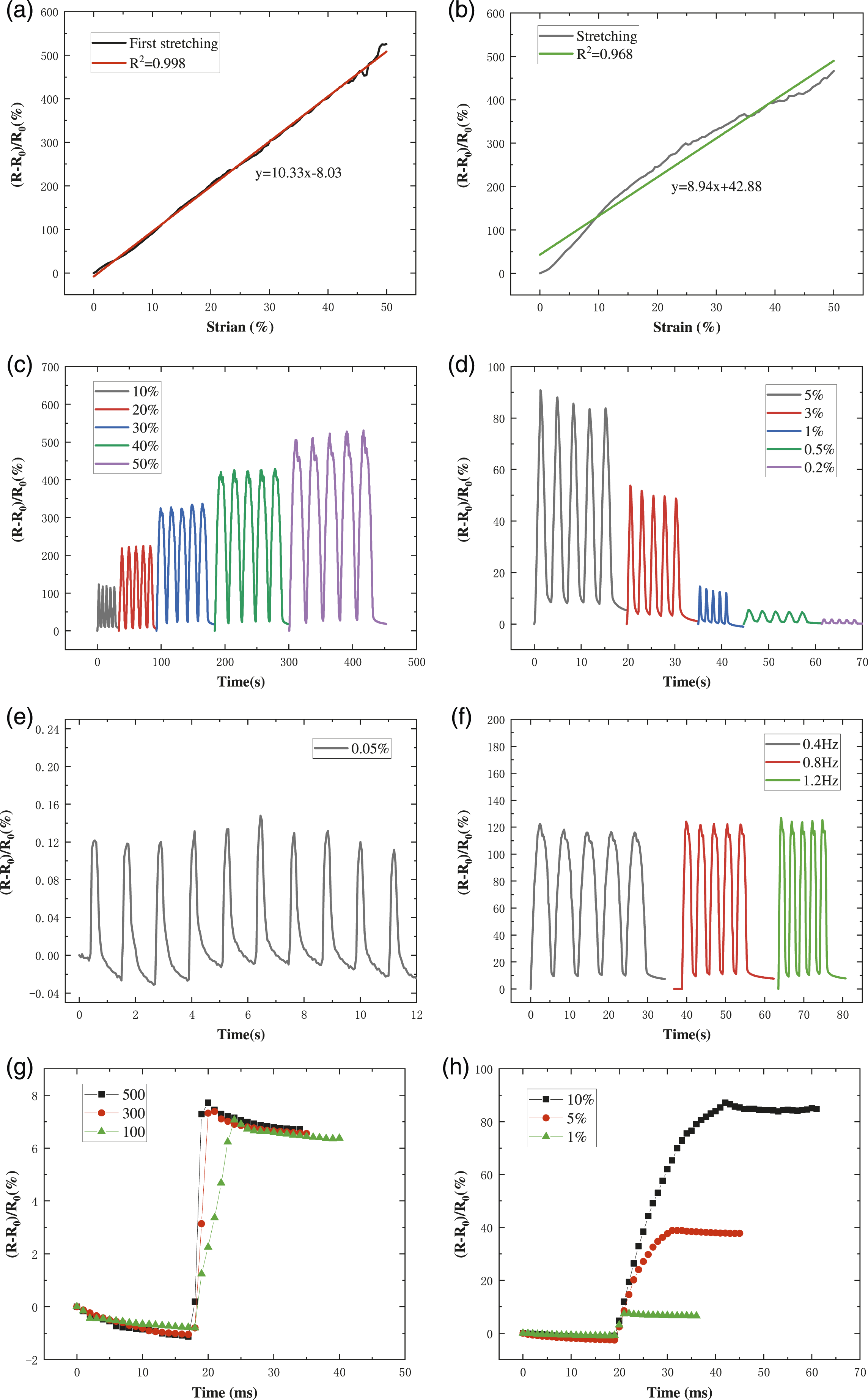
Besides the requirements of high sensitivity and wide detection range, the strain sensors also need to have the characteristic of short response time under different strains and stretching speeds, which is of significance for the real-time detection of fast and complex motion. The AgNPs/DCY composite yarn was tested under the 10, 20, 30, 40, and 50% strain (Figure 5(c)). It is clear that the composite yarn-based strain sensor has excellent electric response towards step cyclic strains, and the relative resistance regularly increases with an increase of strain. Furthermore, it returns to the initial level well after the unloading, so AgNPs/DCY composite yarn exhibits remarkable sensing discernibility and good recoverability. As expected, the (R-R0)/R0 increment of the AgNPs/DCY sensor is consistent with the results in Figure 5(a). When the tensile frequency is increased from 0.4 Hz to 1.2 Hz at 10% strain (Figure 5(f)), the relative resistance change is almost constant. This result showed the excellent elasticity and quick response performance of composite yarn as sensor. Furthermore, the response times of the sensing yarn under different strains and tensile speeds were tested (Figures 5(g) and (h)). At the 1% strain, when the stretching speed was increased from 100 mm/min to 300 mm/min, the response time was shortened from 7 ms to 4 ms, but did not significantly change as the increasing speed up to 500 mm/min. The response time under 10, 5, and 1% strain at 300 mm/min was only 24, 13, and 4 ms respectively, which is shorter than most of previously reported result (see Table 1). This fast response is mainly due to the crack of the deposited conductive layer and the structure change of the covered filaments, and the multi-level hierarchy strengthens and accelerates the response to even subtle changes.
In order to test the repeatability of the yarn as strain sensor, three samples with the same pre-stretching treatment were selected and then stretched for 10 cycles at 20% strain, and the linear sensitivity of each sample was calculated (Figure 6(a)). The relative deviation of the linear sensitivity (GF = 11.45) of three samples at 20% strain is less than 3.29%. It is evident that the same batch of samples have uniform conductive deposition. The yarn was then stretched for 500 cycles at 240 mm/min and 10% strain, as shown in Figure 6(c). During the cycle test, the destroyed and reorganized conductive network of the yarn leads to the resistance of the yarn increase, due to the splitting and closing of the AgNPs conductive layer, slipping between fibers, as well as the viscoelastic properties of the rubber core fiber. In addition, during the rapid stretching cycle, there is no sufficient time for the sensing yarn to recover, so the resistance of the composite yarn will increase with the strain. Therefore, if the cyclic large strain is not sustained in the actual application, the yarn sensor will have more time to recover, and the overall repeatability and stability will be better. To this end, on the premise that the recovery of the elastic deformation is sufficient, the resistance changes of the same sample under 20% strain for 10 times of cyclic stretching for three consecutive days are studied (Figure 6(b)). With the increase of stretching cycles, the linear sensitivity of the sensor changes little and the relative deviation is less than 3.15%. In the application into data glove, the program can be designed to compensate the response drift of the yarn as sensor (Figure 6(d)). (a) The relative resistance changes of the three AgNPs/DCY composite yarn samples under repeated loading-unloading tests with 10 cycles at 20% strain. (b) The relative resistance changes of the AgNPs/DCY composite yarn under repeated loading-unloading tests with 10 cycles at 20% strain for three consecutive days. (c) The relative resistance changes of AgNPs/DCY composite yarn under repeated loading-unloading tests with 500 cycles of stretching at 10% strain, the stretching speed was 240 mm/min. (d) Peak and baseline of relative resistance change of AgNPs/DCY composite yarn under 10% strain for 500 cycles and curve fitting results.
Sensing mechanism of AgNPs/DCY composite yarn
The change in resistance of AgNPs/DCY composite yarn mainly comes from the crack of the deposited conductive layer and the change of yarn structure. Owing to the mechanical mismatching of the AgNPs deposited on the yarn and the elastic core fiber, when the strain sensor was stretched slowly, the conductive layer cracks along with the slip of the fiber (Figure 2(f)), the conductive network changes to increase resistance. In the same strain state, the sensitivity of the yarn sensor increases with the length, width, and density of the microcrack.10,34,35 Therefore, the resistance of the composite yarn changes dramatically with the crack expansion at small strain, showing a high sensitivity. As for the winding structure, the slip between the core fiber, the inner and outer covered filament causes the change of the conductive circuit of the composite yarn. For the single covered filament, the winding angle of the PET multifilament and the spacing between the turns of the PET multifilament will increase with the strain, so that the spiral turns change from contact to separate state (Figures 1(c) and 7). When the turns are in contact with each other, the resistances between adjacent turns are in series mode, which consists of the linear resistance of filaments and the turn-to-turn contact resistance. When the turns are separated from each other, the resistance of the covered filament is the axial resistance of the single covered filament. Therefore, an increase in strain will lead to an increase of the resistance of single covered filament. For double covered filaments, both the inner and outer layers of the composite yarns are uniformly loaded with AgNPs, so it is reasonable that the electrical conductivity of each layer is assumed to be consistent. Without stretching, the overlapped region between the inner and outer covered filament of the yarn is regarded as the resistance of the inner and outer layers in parallel, and the unoverlapped region as the series. With the increase of strain, the winding angle and inter-fibers gap of each of covered filament increase, which causes the exposed areas of the inner covered filament to increase and the contact areas between the outer and inner covered filament decrease (Figure 7). With the decrease of the overlapped area of the inner and outer coverings, the resistance involved in parallel decreases, and the resistance in series increases, which will cause the increase of the total resistance of the composite yarn. In addition, due to the multifilament structure of the covered PET, the slip of the fibers between the PET fiber bundles during the stretching will cause small gaps and increase the resistance of the composite yarn to a certain extent (Figures 1(c) and 7). At large strain state, even though the crack gaps of conductive layer still increase, the resistance change caused by crack is no longer obvious. Compared to the crack effect, under large strain the change of winding angle and inter-fibers slide of the composite yarn are continuous and more obvious, and its resistance change is mainly caused by the change of composite yarn structure. In general, the cooperative effect of the deposited layer crack and yarn structure enables the sensor to achieve the ideal combination of small strain, high sensitivity and wide sensing range, and greatly extends its application range, especially as a human motion detection sensor. SEM images of AgNPs/DCY composite yarns at 0%, 20%, 40%, 60%, 80%, and 100% strain.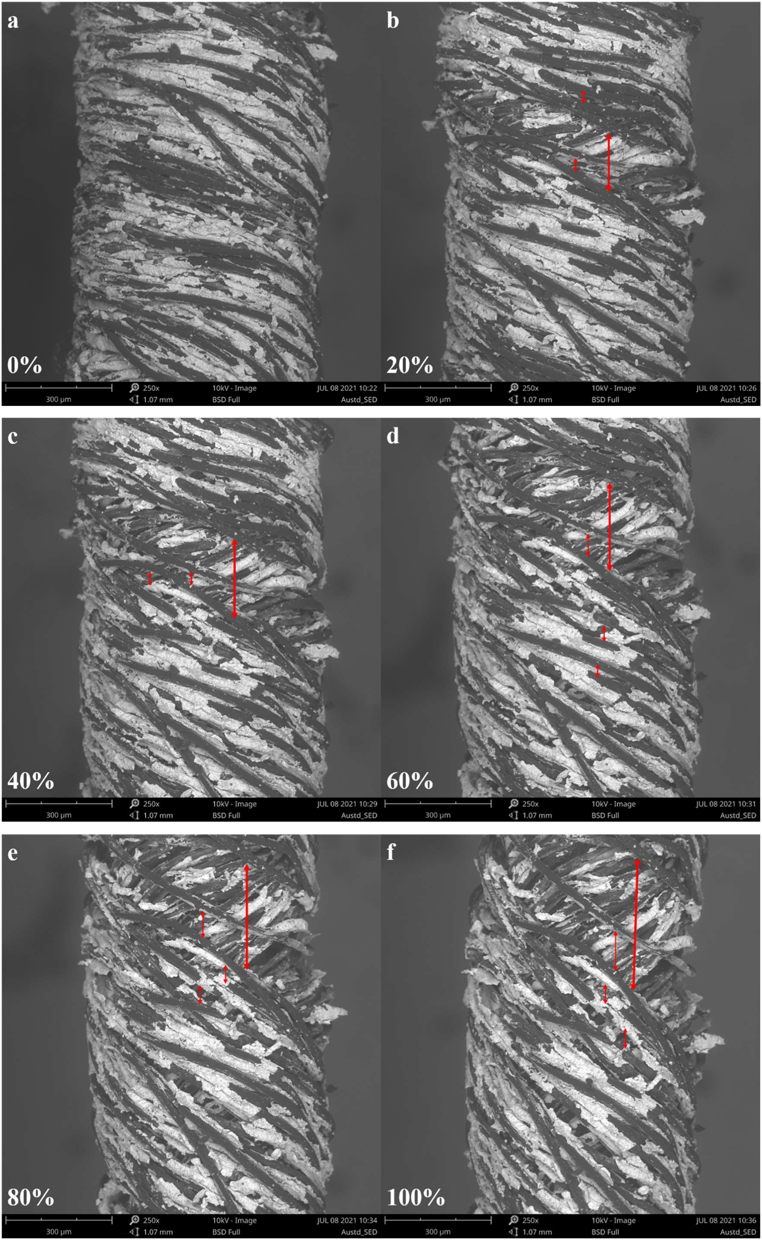
Application of electronic data gloves
To demonstrate the practical application of the composite yarn as strain sensor, the composite yarn was attached directly to the knuckle to monitor the resistance changes during different finger movements. Observably, when the finger bended at different angles, the sensor yarn accurately identified the changes of finger movements and generated different electrical response (Figure 8(a)). In addition, the response of sensing yarn to the dynamic bending and relaxation of finger movement is quick and accurate whether the finger moves slowly or fastly (Figure 8(b)). These observations confirm that the fabricated resistive sensing yarn with high response speed and high sensitivity is feasible in a data glove. Based on the above excellent resistance response to strain, AgNPs/DCY composite yarns were integrated into the normal commercial glove to make gesture recognition data gloves, and retained the signal acquisition and processing hardware of the original commercial data gloves. Specifically, five sensing yarns with the length of 5 cm are folded in half and embedded into the glove, where the sensing yarn of the thumb was inserted into the distal interphalangeal joint (DIP) and those of other four fingers into the proximal interphalangeal joint (PIP), respectively. The sensing yarns were then connected to the data acquisition circuit by fine copper wires. The sensing yarns and leading wires were invisibly embedded into portable data glove well and did not affect its comfort and appearance (Figure 8(d)). Obviously, data glove equipped accurately monitors finger movements (such as patients with hand dysfunction) and recognizes gestures (such as numbers and letters) (Figures 8(c) and (e)). (a) The change in relative resistance of finger movement bending at different angles. (b) The relative resistance changes of the finger movements during 5 times of slow and fast bending. (c) Changes in relative resistance of five fingers in different motion states. (d) Photograph of the electronic data glove and partial enlarged of the location of the sensing yarn. (e) Photographs of data glove text information corresponding to different gestures.
Conclusion
In summary, by a facile in situ chemical reduction technique, a strain sensing yarn consisting of elastic double covered yarn as substrate and AgNPs as complex conductive network was developed. It has the characteristics of good linearity (R2 = 0.96), ultralow detection limit (0.05%), wide linear strain-response range (50%), and high linear sensitivity (GF = 10). The sensing yarn shows a timely electromechanical response under various deformations, with only 24 ms response time at 10% strain, and no obvious damage in 500 continuous stretching-releasing cycles at 10% strain. This remarkable sensing performance is attributed to the synergistic sensing mechanism, that is, the crack propagation of the conductive layer deposited on the surface of the rubber core fiber and the layered helical structure change of the inner/outer wrapped filaments. Finally, the strain sensing yarn was used to monitor finger motion by sign recognition data glove with five fingers, and the successful real-time recognition of various gestures demonstrated its good performance and practicability. This work sheds light on the potential of AgNPs/DCY composite yarn as a strain sensor in medical health detection, human-computer interaction, etc.
Footnotes
Declaration of conflicting interests
The author(s) declared no potential conflicts of interest with respect to the research, authorship, and/or publication of this article.
Funding
The author(s) disclosed receipt of the following financial support for the research, authorship, and/or publication of this article: This work was supported by the Central University Basic Research Fund of China, Natural Science Foundation of Shanghai.