
Abstract
Engineering surface morphologies of nanofibers has been attracting significant consideration in numerous fields and applications. Among different methods of generating nanofibers, electrospinning is the most widely adopted technique owing to the ease of forming nanofibers with an extensive range of properties and its exceptional advantages, such as the variety of shapes and sizes, as well as the adaptable porosity of nanofiber webs. The branched structure is considered one of the most attractive structures for scientific researchers due to its outstanding properties (e.g., high-specific surface area and extremely tiny diameters of branched nanofibers). Therefore, this work is the first one that summarizes the strategies and methods, reported so far, of producing branched nanofibers of different materials. The material types, formation mechanisms, characterizations, and applications of the branched nanofibers generated through different techniques will be discussed in detail in this study. We believe this work can be served as an important reference for the preparations, strategies, and applications of the branched nanofibers.
Introduction
Nanomaterials such as nanofibers, nanotubes, nanocomposites, nanoparticles, nanorods, and molecular self-assembled materials have received a great deal of interest in recent years. Nanomaterials feature a variety of unique electrical, mechanical, chemical, and other properties that have resulted in a scientific revolution in the development of new devices and materials.1,2,3 Most nanomaterials have been formed by synthetic bottom-up methods and were discontinuous objects in many cases, leading to difficulties in their alignment, assembly, and processing for desirable applications. 4 In contrast, nanofibers which are fibers with diameters in the nanometer range can be formed easily. 5
Nanofibers can be generated by different techniques such as template synthesis, phase separation, drawing, wet spinning, and self-assembly.6-10 However, most of these methods have disadvantages because occasionally procedures are not appropriate for some polymers, are not manageable, and have no adaptation over the orientation and diameter of fibers.
Since the late 1990s, the popularity of nanofibers has been rising as evident from expanding the number of publications. Nanofibers have unique properties (e.g., small diameter of fibers,11,12 high specific surface area,13,14 flexibility,15,16 good pore structures,17,18 ease of functionality,19,20 low density,21,22 excellent mechanical properties,23,24 and exceptional adjustability25,26). Therefore, they can be used in different areas such as energy harvesting,27-29 antibacterial applications,30,31 tissue engineering,32,33 biomedical applications,34-37 self-cleaning surfaces,38,39 sensors,40,41 catalyst,42,43 filtrations,44,45 and food packaging.46,47
Since the surface morphology of nanofibers (e.g., porous fibers,48-50 crimped fibers,51,52 cactus-like nanofibers, 53 wrinkled fibers,54,55 grooved fibers,56-59 rough fibers,49,60 tree-like fibers,61,62 ribbon fibers,63,64 butterfly wings fibers,65,66 and beaded fibers,67,68 etc.) can enhance or alter the properties and applications of nanofibers, branched nanofibers provide outstanding specific surface area, 69 tiny diameters,70,71 excellent biological properties, 72 good piezoelectricity, 73 large porosity, 69 outstanding mechanical properties, 73 good thermal stability, 74 excellent thermal insulation 74 and so on hence have multifunctional capabilities. Therefore, the branched structure has shown great potential in various applications such as filtration, 69 energy harvesting, 73 oil-water separation, 70 and energy storage. 75
Since 2004, the number of studies on branched nanofibers has been increasing. However, up to now, there is no review paper about this structure. To the best of our knowledge, this is the first work comprehensively and systemically reviews the importance of the branched structure.
The objective of this review is to shed light on the significance of branched nanofibers owing to their outstanding properties, resulting in their ability to be used successfully in multiple applications.
This review summarizes the materials, preparation methods, characterizations, and applications of the branched nanofibers. We believe this study can serve as a good reference for the production, characterizations, and applications of the branched nanofibers from different materials.
Electrospinning’s fundamental concept
As an increasingly extensive nanofibers formation method, electrospinning is an effective and adaptable method for producing fibers with diameters ranging from a few nanometers to some micrometers.76-78 The gathering of these fibers forms electrospun nanofiber nonwoven webs.
The discovery of this technique dates back to 1934 when fibers were spun from cellulose acetate/acetone solution by Anton Formhals. Electrospun nanofibers have unique properties such as high porosity, high surface area, and excellent mechanical, chemical, and electrical properties, resulting in making them a favorable demand for researchers.
Electrospinning involves electrification of a liquid droplet to generate a jet, and subsequent stretching and elongation of jet to form fiber(s). The electrospinning device contains three major components: reservoir (including syringe pump, syringe, and syringe needle), conductive collector (stationary or rotating), and high-voltage power supply which can be either alternating current or direct current as demonstrated in Figure 1.48,79 Schematic diagram of the electrospinning apparatus with inset of Taylor cone.
48

A polymer solution or melt is extruded through a tinny nozzle to form a liquid droplet as a result of surface tension. When the voltage is applied between the needle and collecting electrode, an electric field will be produced resulting in accelerating and elongating an electrically charged polymer jet to form Taylor cone at the needle syringe top, subsequently ejecting the jet from the cone toward the collector. When the jet flying toward the collector, it stretches and whips while solvent(s) evaporates resulting in forming fibers on the collector. 80
It is worth mentioning that the structure of electrospun nanofibers and their properties can be affected by (I) the working parameters of electrospinning process represented by solution parameters (molecular weight,54,81 polymer concentration,56,82 viscosity,83,84 surface tension,56,85 and conductivity86,87), ambient parameters (temperature and relative humidity),49,88 and processing parameters (applied voltage,76,89,90 flow rate,76,91 distance between the tip of the needle and the collector (DTC),76,92 diameter of the needle,76,93 and collector type94-96), (II) constituents of composite or hybrid nanofibers,97-99 (III) post-processing treatments such as heat treatment, chemical treatment which enable the production of fibers without the need to change the spinning parameters, leading to modify the surface morphology and properties of materials,100-103 and (IV) electrospinning types which are grouped mainly to electrospinning based on basic needle and needleless electrospinning.80,104,105
Generating of the branched nanofibers
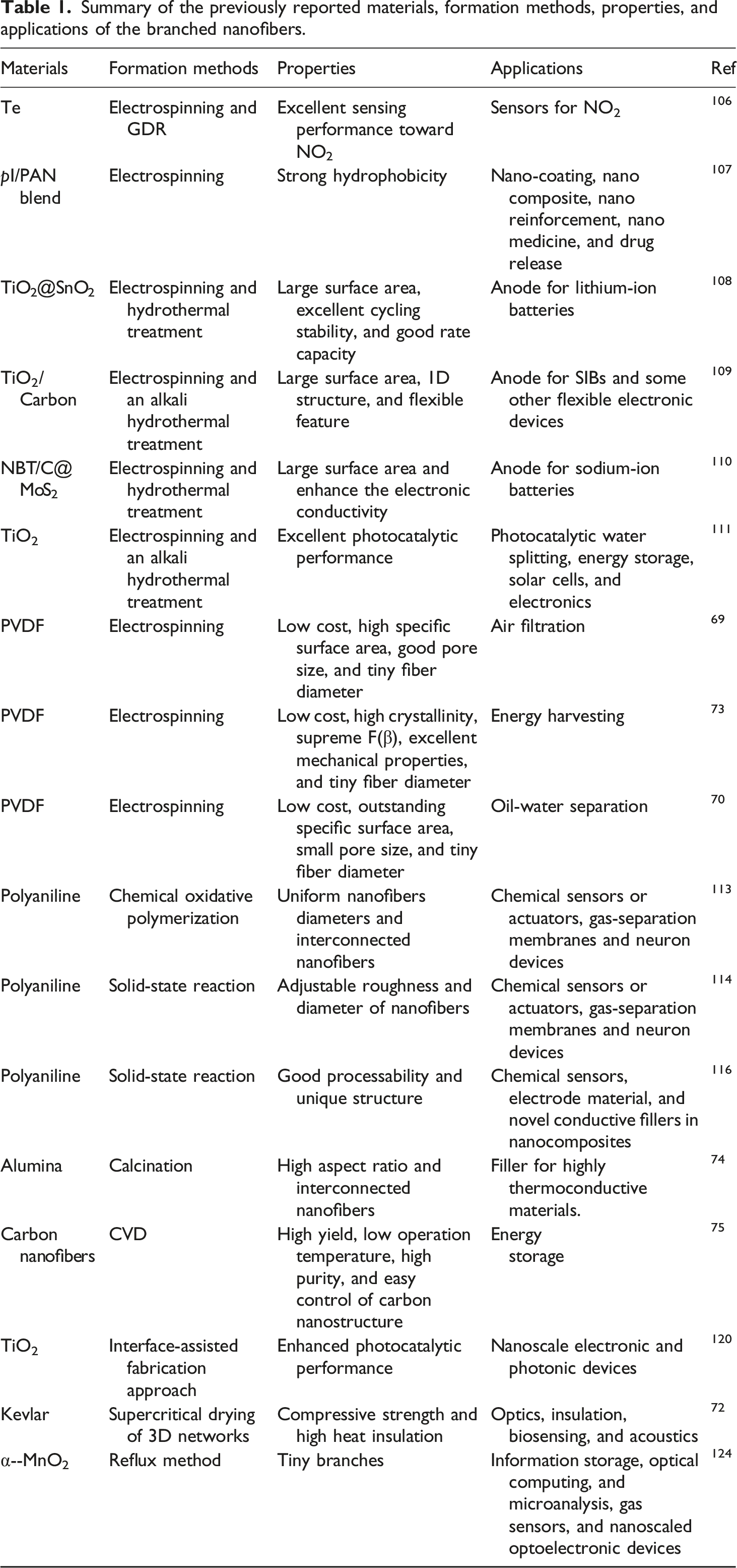
Summary of the previously reported materials, formation methods, properties, and applications of the branched nanofibers.
Formation methods
Branched nanofibers have been generated by different methods which are electrospinning, chemical oxidative polymerization, solid-state reaction, calcination, chemical vapor deposition method (CVD), interface-assisted synthesis, supercritical drying, and reflux.
Electrospinning
The widest method used for generating branched nanofibers is electrospinning owing to its outstanding advantages as mentioned in the previous section. Herein, various studies about generating electrospun branched nanofibers are reviewed.
Park et al.
106
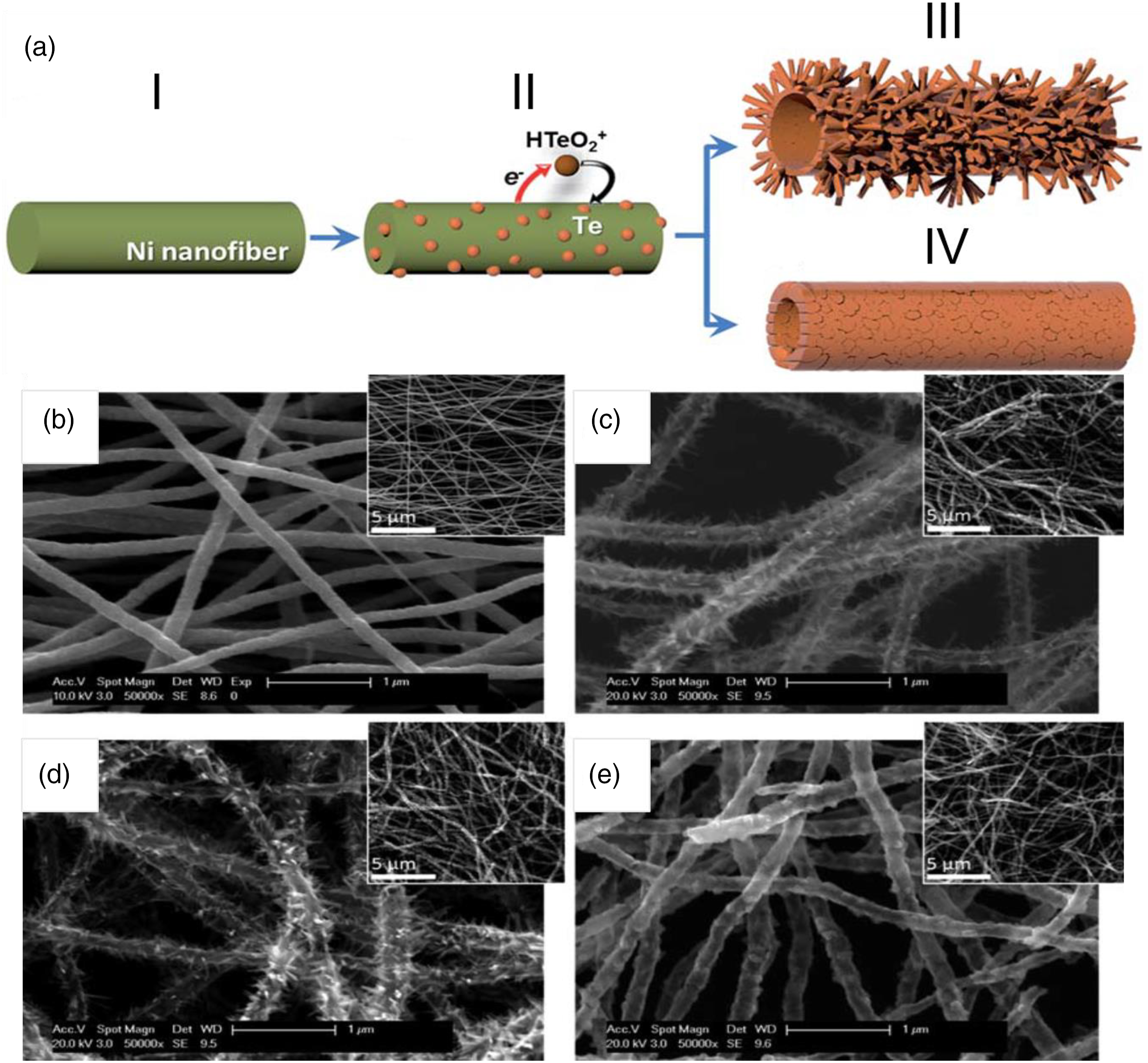
described the synthesis of branched tellurium (Te) hollow nanofibers by the combination of electrospinning and galvanic displacement reaction (GDR) and demonstrated their excellent sensing performance toward nitrogen dioxide (NO2) at room temperature (Figure 2). The morphologies (smooth or branched) and wall thickness of hollow nanofibers were precisely controlled by adjusting the electrolyte composition. They found that the branched Te hollow nanofibers show excellent sensing performance in terms of greater sensitivity, and faster response/recovery times toward NO2 compared to smooth Te hollow nanofibers. (a) Schematic illustration of GDR of nickel nanofibers to form smooth or branched Te hollow nanofibers: electrospun Ni nanofiber (I) is galvanically displaced by Te (II). As the reaction continues, branched Te hollow nanofibers (III) or smooth Te hollow nanofibers (IV) are produced depending on the concentration of HTeO2. SEM images of electrospun Ni nanofibers (b) and branched Te hollow nanofibers synthesized from 0.5 (c) and 1.0 (d) mM HTeO2+. Smooth Te hollow nanofibers synthesized from 10 mM HTeO2+ (e). Inset images display low magnification images of Te nanofibers.
106
Konno et al. 107 fabricated core/shell-like structured branched nanofibers by a phase separation process using simple polymer blend polyacrylonitrile (PAN) and polyimide (PI) solutions with electrospinning. They found that pI/PAN blend ratios (from 50/50 to 80/20) provided core/shell-like branched nanofiber structures. Moreover, they revealed that the applied voltage during the electrospinning process and the PAN content created different branching ratios in the blended nanofibers.
Zhu et al.
108
prepared hierarchically heterostructured titanium dioxide (TiO2)@ stannic oxide (SnO2) core-branch nanofibers by a combination of electrospinning and hydrothermal treatment (Figure 3(a)). The hydrothermally grown SnO2 nanocubes have solid contact with the TiO2 nanofibers, approaching the morphology of a string of beads (Figures 3(b)–(d)). Consequently, SnO2 nanocubes on the surface of the TiO2 nanofibers have the ability to provide a larger surface area for lithium insertion/extraction which could lead to large reversible capacity, while the backbone of TiO2 nanofibers can sustain the structure stability during the cycling. (a) Schematic diagram of the synthesis process of hierarchically heterostructured TiO2@SnO2 core-branch nanofibers. SEM images of b) 10 wt% TiO2@SnO2 nanofibers, c) 20 wt %TiO2@SnO2 nanofibers, d) 30 wt %TiO2@SnO2 nanofibers.
108

Wang et al.
109
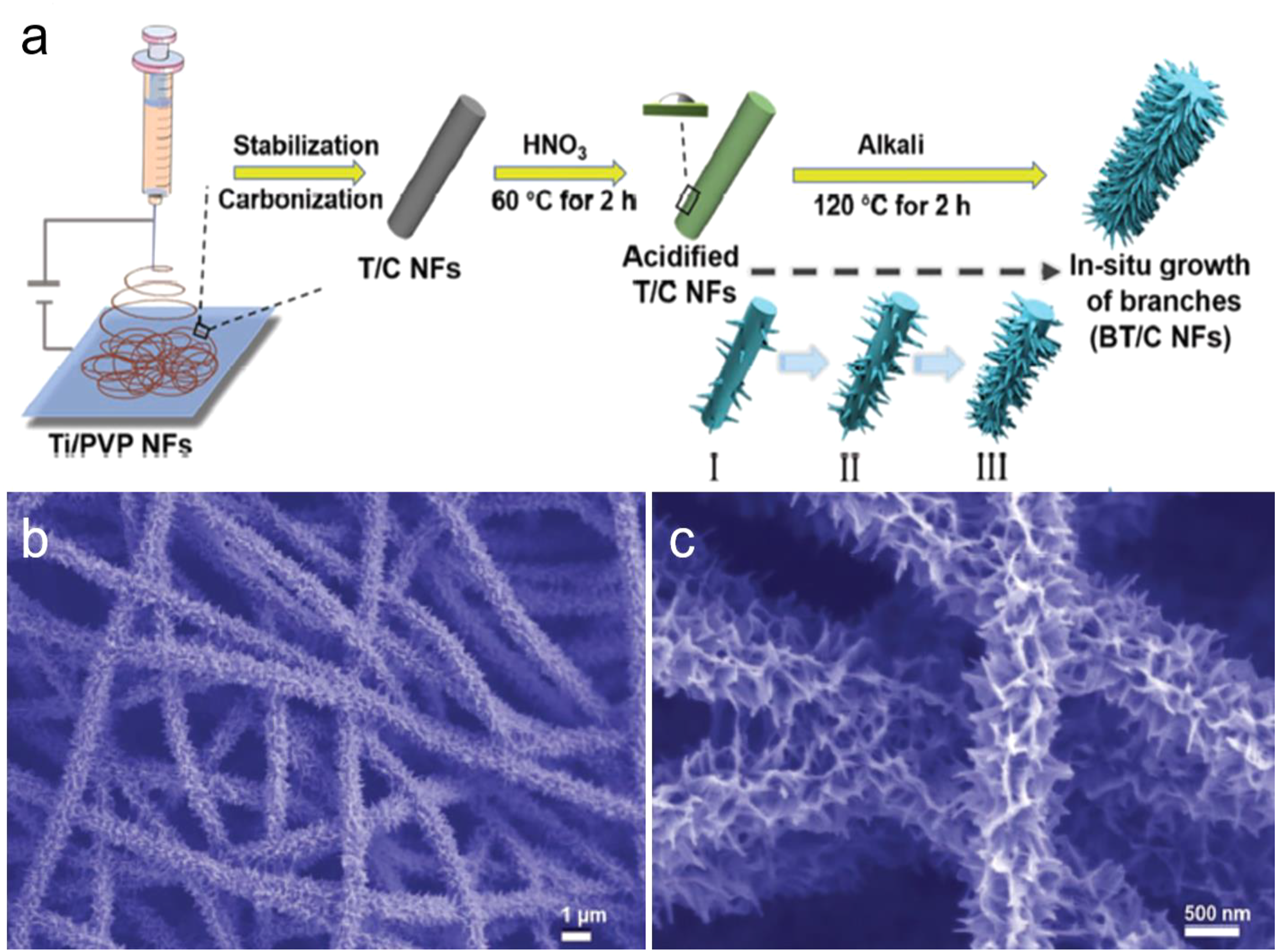
reported a rational design of free-standing branched TiO2/carbon nanofibers generated via electrospinning and an alkali hydrothermal treatment method. The as-prepared branched TiO2/carbon nanofibers are well performed with a flexible feature, large surface area, and 1D structure which are beneficial for pseudocapacitive contribution as well as ion and electron transfer (Figure 4). The in situ fabrication provides the materials with strong structural stability, as well as carbon can increase the electrical conductivity of the branched TiO2/carbon nanofibers electrode and suppress the agglomeration of TiO2 nanoparticles. (a) Schematic illustration of the synthesis process of the branched TiO2/carbon nanofibers. b, c) SEM images of branched TiO2/carbon nanofibers with different magnifications, respectively.
109
Wang et al.
110
also demonstrated the design and synthesis of a novel architecture of expanded molybdenum disulfide (MoS2) nanosheets grown on nitrogen-doped branched TiO2/carbon nanofibers (NBT/carbon@MoS2) by using electrospinning subsequently with hydrothermal treatment (Figure 5). Their design has many advantages. i) The branched TiO2/carbon nanofibers can not only function as the mechanical backbone and conductor medium to enhance the electronic conductivity of MoS2 but also afford a large surface area to grow MoS2; ii) the TiO2 in the NBT/carbon @MoS2 nanofibers can limit sulfur dissolution issue during cycling, whereas the doping of nitrogen can facilitate the transfer of both Na+ ions and electrons; iii) the contribution of extrinsic pseudocapacitance also enhances the kinetics. (a) Schematic illustration of the preparation process of NBT/carbon @MoS2 nanofibers and NT/carbon @MoS2 nanofibers. SEM images of (b,c) nitrogen-doped TiO2/carbon nanofibers, (d,e) nitrogen-doped branched TiO2/carbon nanofibers, (f,g) NT/carbon @MoS2 nanofibers, and (h,i) NBT/carbon @MoS2 nanofibers at different magnifications.
110

Nasir et al.
111
prepared a 1D nanofiber of TiO2 by electrospinning and formed a branched structure on the fiber by following the alkali hydrothermal method (Figure 6). The CVD was adopted, first to load g-C3N4 QDs then nanoflakes of tin (II) selenide (SnSe2) on the branched fiber of TiO2, and make a strong heterojunction. The composite exhibited excellent photocatalytic performance by producing hydrogen about 2375 μmol g−1.h−1 having a quantum efficiency of HER more than 16% at 420 nm. The photoluminescence, time decay fluorescent spectra, and photoelectrochemical results approved that SnSe2 not only reduces the charge recombination by increasing the transfer of electrons but also provides an active site for hydrogen production as a co-catalyst. (a) Schematic illustration of the synthesis method for hierarchically branched TiO2 nanofibers/Cn/SnSe2. FESEM Images b) uniform and smooth as-electrospun TiO2 nanofibers; c) hierarchical branched TiO2 fiber after alkali hydrothermal treatment; d) branched TiO2 fiber after decorating graphitic-carbon nitride quantum dots (g-C3N4 QDs) on it, inset is the magnified image of the same sample; e) the hairy structure having g-C3N4 QDs and also SnSe2 nanoflakes, inset is the magnified image of the same sample in which nanoflakes can be seen on branches.
111

Zaarour et al.
69
fabricated a polyvinylidene fluoride (PVDF) branched nanofiber web with a diameter of less than 50 nm via one-step electrospinning (Figure 7). The branched structure was produced by adding a Tetrabutylammonium chloride (TBAC) to 10% PVDF/(ACE/DMF) solution at the solvent ratio of 1:2 with an applied voltage of 18 kV, tip to collector distance of 18 cm, flow rate of 1.5 mL/h, and RH of 10%. The formation mechanism of the branched structure was attributed to the presence of TBAC which could be dissolved easily in the PVDF solution and enhances the electrical conductivity of the solution. When the density of the jet’s charges exceeds a certain threshold value, the electric forces overcome the surface tension resulting in the schism of the jet. Moreover, the TBAC decreased the forces between the PVDF molecules thanks to its space steric structure and accordingly serving for the schism of the jet. The results proved that the branched structure increases significantly the specific surface area and reduces the pore size of the nanofiber webs, resulting in enhancing the ability for catching the small particles. In other words, this structure has the ability to serve successfully in the field of air filtration. (a) Schematic diagram illustrating the electrospinning process of branched fibers. SEM images of (b) 15% PVDF/(ACE/DMF), (c) 10% PVDF/(ACE/DMF), (d) 10% PVDF/(ACE/DMF)-TBAC.
69

Zaarour et al. 73 also electrospun directly branched PVDF nanofibers with a diameter of less than 40 nm. The branched structure was formed by adding 0.2 mol/L TBAC to 8% PVDF/(THF/DMF: 1/2) solution at the relative humidity of 10%. The results showed that the branched structure has high crystallinity, supreme β phase content (F(β)), and excellent mechanical properties. Therefore, this structure can be used successfully in the field of energy harvesting.
Zaarour et al. 70 also generated branched PVDF nanofibers directly with a diameter of less than 35 nm via one-step electrospinning. The branched structure was formed by adding 0.2 mol/L TBAC to 8% (THF/DMF: 1/2) PVDF at a temperature of 20°C, relative humidity of ∼10%, applied voltage of 18 kV, and flow rate of 1.5 ml/h. The results of N2 physical adsorption-desorption isotherms showed that the branched PVDF nanofibers sorbent has an outstanding specific surface area of 70.98 ± 8.45 m2/g. As a result, this structure can be served successfully in the field of oil cleanup.
Chemical oxidative polymerization
This method is often classified as a kind of polycondensation since chain growth is complemented by the formation of low-molecular products. It is used for the synthesis of polymeric (oligomeric) materials from different classes of monomers. 112
Li et al.
113
demonstrated a practical and simple route to the synthesis of branched polyaniline nanofibers with diameters between 60 and 90 nm by chemical oxidative polymerization of aniline in a surfactant gel, which was obtained using a mixture of hexadecyltrimethylammonium chloride (C16TMA), acetic acid, aniline, and water at −7°C (Figure 8). Moreover, they investigated the effects of the concentration of C16TMA, dopant, and solvent on the morphologies of polyaniline. They found that there is a positive relationship between the concentration of C16TMA and the lengths of the polyaniline branches, while dopant has no obvious influence on the morphologies of polyaniline. Furthermore, the solvent used has a big effect on the diameter of branched nanofibers. SEM images of dendritic polyaniline nanofibers synthesized with 0.3 mol/L C16TMA at −7°C in acetic acid: (a, b) at low magnification and (c) at high magnification. 2. (d) SEM image of dendritic polyaniline nanofibers synthesized with 0.3 mol/L C16TMA at −7°C in ethanol solution.
113

Solid-state reaction
The solid-state chemical reaction is considered an efficient, simple, surfactant-free, and convenient chemical reaction method that has been widely used to prepare various nanomaterials. Since the liquid monomer aniline forms solid salts with mineral acids, for example, aniline hydrochloride (mp. 196–198°C), it is possible to use room temperature solid-state polymerization of a solid anilinium salt to produce polyaniline nanomaterials. 114
Du et al.114,115 demonstrated a facile solid-state mechanochemical route for branched polyaniline nanofibers without using any surfactants, organic acid, and additional templates. They prepared branched polyaniline nanofibers with a solid-state reaction simply between the monomer and oxidants (Figure 9(a)–(d)). They found that the formation of branched nanofibers is possibly related to the mechanochemical oxidation polymerization process and the linear nature of the polyaniline molecule chains. It is worth mentioning that the structure of products depends on the rate of nucleation and growth of the ultimate products in the solid-state reaction.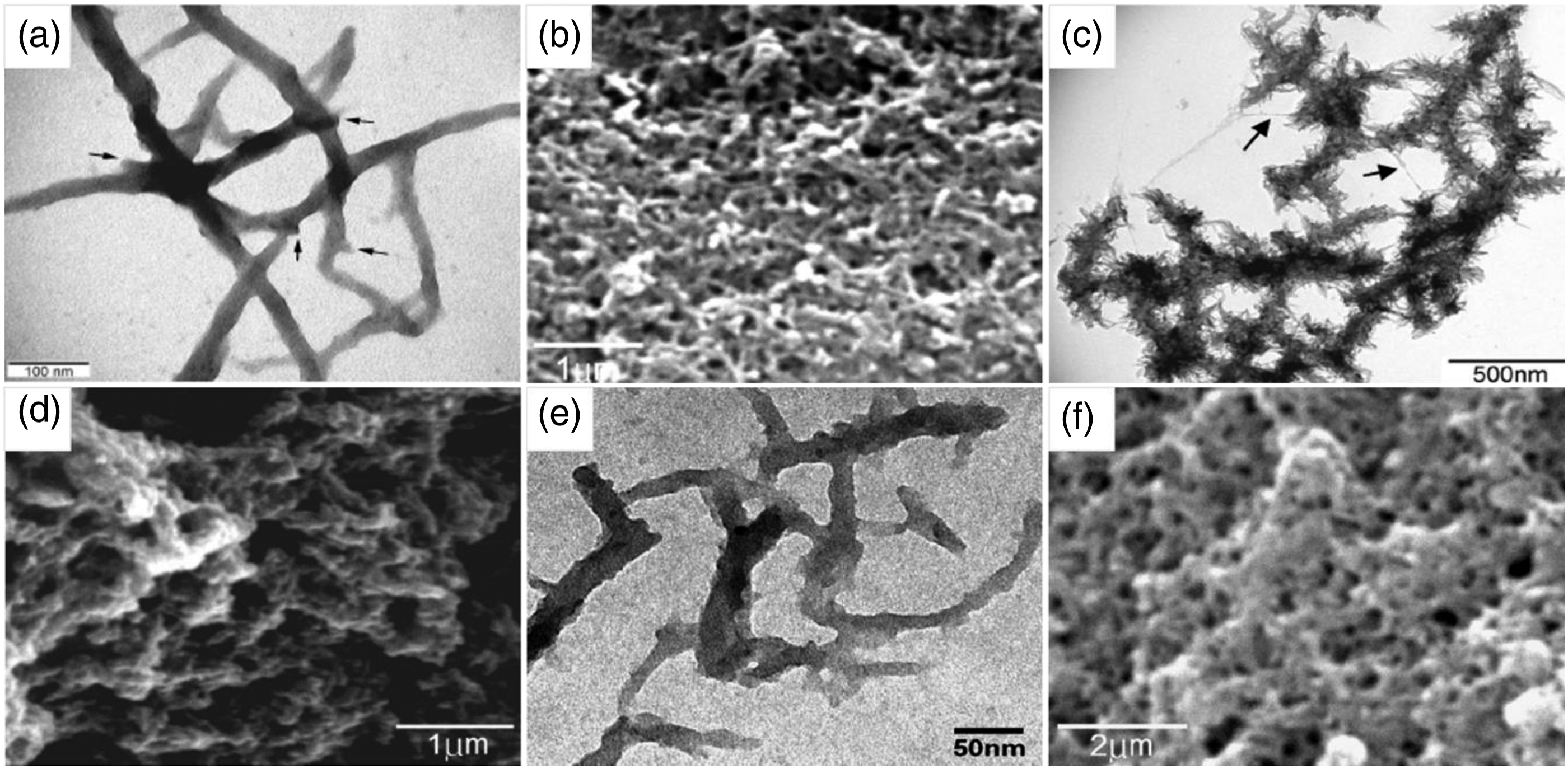
Zhou et al. 116 synthesized branched polyaniline nanofibers with diameters of 15–40 nm and lengths about several hundred nanometers using iron(III) chloride (FeCl3) as the oxidant by solid-state reaction method. The effects of reaction time and concentration of the oxidant (Figure 9 (e)–(f)). They studied the effect of the reaction time and concentration of the oxidant on the morphology of products. The results showed that there is no relationship between the reaction time and the morphology of products, while the concentration of the oxidant has little effect on it.
Calcination
Calcination means heating a solid chemical compound to high temperatures in the absence or limited supply of air or oxygen to remove volatile substances or impurities and/or to incur thermal decomposition. 117
Shimazaki et al.
74
fabricated a branched alumina nanofiber filler by the calcination of an alumina precursor, aluminum isopropoxide, adsorbed onto a paper filter (Figure 10). (a) SEM image of alumina nanofiber filler with a branched structure. (b) Cross-sectional SEM images of nanocomposites prepared by curing epoxy resin with sheet-shaped filler and (c) branched filler dispersed in resin.
74

The branched nanofiber filler is advantageous as the constituent nanofibers are interconnected with each other and have a high aspect ratio. This leads to an increase in the number of junctions among nanofibers resulting in yielding more thermoconductive path in the composite. Moreover, alumina is used a lot as an industrial material for thermoconductive filler owing to its high aspect ratio and its high thermoconductivity, which allows the creation of more thermoconductive path in the resin at a lower filler concentration. They report a high thermal conductivity of the polymer composite containing the branched nanofiber filler. They found that the branched structure of the nanofiber filler is effective for highly thermoconductive materials.
CVD
CVD is a vacuum deposition technique used to generate high-performance, high quality, and solid materials. Generally, this method is used in the field of semiconductor industry. 118
Among the different techniques that have been applied for the synthesis of carbon nanofibers and carbon tubes, catalytic CVD appears the most promising because of low operation temperature, high yield, high purity, and easy control of carbon nanostructure by adjusting the process parameters. Generally, the CVD method requires a catalyst in the form of small particles on a solid support. The choice of a metallic catalyst, such as nickel, cobalt, or iron has been shown to influence the growth and morphology of the generated carbon nanomaterials.
Tao et al.
75
reported the synthesis of multi-branched carbon nanofibers with a porous structure using the catalyst Cu doped with the alkali-element (Li, Na, or K) via a simple thermal CVD method (Figure 11). They found that alkali-element doping plays a key role in this synthesis process. (a) Shows low magnification and (b) the high-magnification FESEM images of as-prepared carbon nanofibers. (c) The FESEM image of carbon nanofibers grown from a catalyst particle. (d) The TEM image of carbon nanofibers grown from the catalyst particle, the inset is the corresponding SAED pattern of the catalyst particle. (e) shows a high-magnification TEM image of carbon nanofibers, and (f) the high-resolution TEM image of the carbon nanofibers.
75

Interface-assisted synthesis
This method is a powerful emerging tool for the synthesis of conducting polymers on a large scale. Interface-assisted synthesis strategies offer effective nanostructure control in a confined two-dimensional space. 119
Wang et al.
120
employed water–dichloromethane interface-assisted hydrothermal technique to grow rutile TiO2 nanowires on electrospun anatase TiO2 nanofibers, using highly reactive titanium tetrachloride (TiCl4) as a precursor. The water–dichloromethane interface inhibited the generation of rutile nanowires in the water phase, however, promoted the selective radial growth of densely packed rutile nanowires on anatase nanofibers to produce a branched heterojunction (Figure 12). The length and density of rutile nanowires could be readily regulated by maneuvering reaction parameters. The formation mechanism of the branched heterojunction involved (1) the entrapment of rutile precursor nanoparticles at the water–dichloromethane interface, (2) the growth of rutile nanowires on anatase nanofibers via Ostwald ripening through the scavenging of interface-entrapped rutile nanoparticles. The heterojunction formed at anatase nanofiber and rutile nanowire improved the charge separation of both under ultraviolet excitation, as verified by photoluminescence and surface photovoltage spectra. (a) Scheme for the formation process of hyperbranched TiO2 heterostructures. b-d) SEM image of different samples: (b) low magnification image of the sample which preheated for 2h (AR1); (c) high-magnification image of sample AR1; (d) low magnification image of the sample which preheated for 4h (AR2); (e) high-magnification image of sample AR2.
120

Supercritical drying
Supercritical drying is also called critical-point drying, supercritical extraction, and supercritical lyophilization. It is a method for transforming liquid in a substance into gas in the absence of capillary stress and surface tension. This technique is usually used to convert gels into aerogels. It can be said that this process is performed to replace the liquid in a material with a gas and isolate the solid component from the material without destroying the material’s delicate nanostructured pore network.121,122
Li et al.
72
prepared biomimetic aramid nanofibers aerogels made from branched aramid nanofibers derived from Kevlar with the structure replicating articular cartilage by supercritical drying of 3D networks held together by hydrogen bonds. Thanks to the branching morphology of the nanofibers, the 3D nanoscale networks with high interconnectivity and extensive percolation can be got (Figure 13). This structure-based aerogel exhibited high porosity, good thermal stability, high special surface area, and excellent thermal insulation. Scanning electron microscopy images of branched aramid nanofiber aerogels showing the effects of different exchange solvents: (A) deionized water, (B) no exchange solvent, (C) ethanol, and (D) n‐heptane.
72
Reflux
Reflux is a method involving the condensation of vapors and the return of this condensate to the system from which it originated. It is used in industrial and laboratory distillations. It is also used in chemistry to supply energy to reactions over a long time. 123
Zheng et al.
124
synthesized pure multiple branched α -MnO2 nanofibers based on the use of MnO−4 to oxidize Mn2+ under a weak acidic condition through a simple refluxing in the absence of surfactants or catalysts as templates (Figure 14). The results showed that these nanofibers were produced by two-step epitaxial coalescence of small primary nanofibers. Here in, the small nanofibers were merged through the (1 1 0) plane to procedure larger monocrystalline nanofibers, which then attached one by one through the two of (1 1 0) and (2 1 1) planes, resulting in the formation of multiply branched structures. TEM images of the samples prepared for different reaction periods (a) 1 h; (b) 3 h; (c) 5 h; (d) 10 h.
124

Applications of the branched nanofibers
Based on the special characters of branched nanofibers, they have received much consideration for use in various applications. Herein, different applications of branched nanofibers are reviewed.
Energy harvesting
Energy harvesting (also known as energy scavenging or power harvesting) is defined as capturing various amounts of energy from different naturally occurring energy sources, collecting them, and storing them for later use. 125 Electrospun branched piezoelectric nanofibers have shown great potential in the field of energy harvesting.
Zaarour et al.
73
proved that the branched PVDF structure has supreme F(β), high crystallinity, and excellent mechanical properties. Furthermore, the PENG based on the branched PVDF nanofiber web showed outstanding electrical outputs of ∼2.6 V and ∼3.1 μA due to its high friction area, high F(β), and small diameters (Figure 15). Since PVDF branched structure has many advantages, it has the ability to serve successfully in the field of energy harvesting. (a) Schematic diagram of the PENG. (b) Digital photo of the actual PENG. (c) Voltage output generated by the PENG based on different samples. (d) Current output generated by the PENG based on different samples.
73

Air filtration
Air filtration is a technique used widely to remove particles from an air stream owing to its relative ease and flexibility. Filters fabricated from nanofibers are the best choice for air filtration due to their excellent filtration capacity and improved service life in real operating environments. 126 Therefore, branched nanofibers have been shown great potential in the field of air filtration.
Zaarour et al.
69
found that PVDF branched nanofiber web with a diameter of less than 50 nm showed great potential in the field of air filtration. The results showed that the branched structure enhances significantly the specific surface area and decreases the pore size of the nanofiber webs, resulting in improving the ability for trapping the small particles. Moreover, the extremely tiny diameter of branched nanofibers (<10 nm) increases the van der Waals attractive forces between nanofibers and particles. As a result, the filtration performance of air filters can be enhanced according to the ultra-low penetration air standard (the level of U15) (Figure 16). (a) Filtration efficiency, (b) pressure drop, and (c) quality factor of electrospun webs at different basis weights of webs. (S1, S2, S3 represent beaded-free nanofibers, beaded nanofibers, branched nanofibers, respectively).
69

Oil cleanup
Oil spills pose a significant hazard to the environment in general, and the marine ecosystem in particular. This pollution is due to human activity such as releasing oil to coastal waters or oceans from drilling rigs and wells, offshore platforms, tankers, etc. Studies proved that sorbents fabricated from nanofibers are the best choice for oil cleanup owing to their high specific surface area. 127 Therefore, branched nanofibers are in great demand for researchers interested in the field of oil cleanup.
Zaarour et al.
70
studied the oil absorption capacity of PVDF sorbent based on the branched structure. This sorbent showed an outstanding oil absorption capacity of 93 ± 3.2 g/g, 122 ± 7.3 g/g, and 149 ± 10.1 g/g for olive oil, motor oil, and silicon oil, respectively, owing to its high specific surface area (Figure 17). These results are ascribed to the small diameter of fibers generated and the existence of branches with a tiny diameter (∼5 nm) which allows ensnaring oil droplets between them. (a) Specific surface area of samples M1, M2, and M3. (b) The nitrogen adsorption isotherms of the samples M1, M2, and M3. c) Pictures of oil absorption. (I) 50 mL of a water-oil mixture (1:1) without sorbent, (II) during absorption, (III) during draining. d) Oil absorption capacities of the samples M1, M2, and M3. (M1, M2, M3 represent beaded-free nanofibers, beaded nanofibers, branched nanofibers, respectively).
70

Energy storage
Energy storage is defined as capturing the energy generated at one time for use at a later time to reduce disparities between energy production and energy demand. Devices that store energy are called batteries or accumulators.128,129
Tao et al. 75 prepared successfully branched carbon nanofibers with porous structure via a simple thermal CVD method. They used their design as polarized electrodes, as a result, electrochemical double-layer capacitors with a remarkable specific capacitance of ca. 297 F/g was obtained with 6 M KOH as the electrolyte. They found that carbon nanofibers have great potential in energy storage applications.
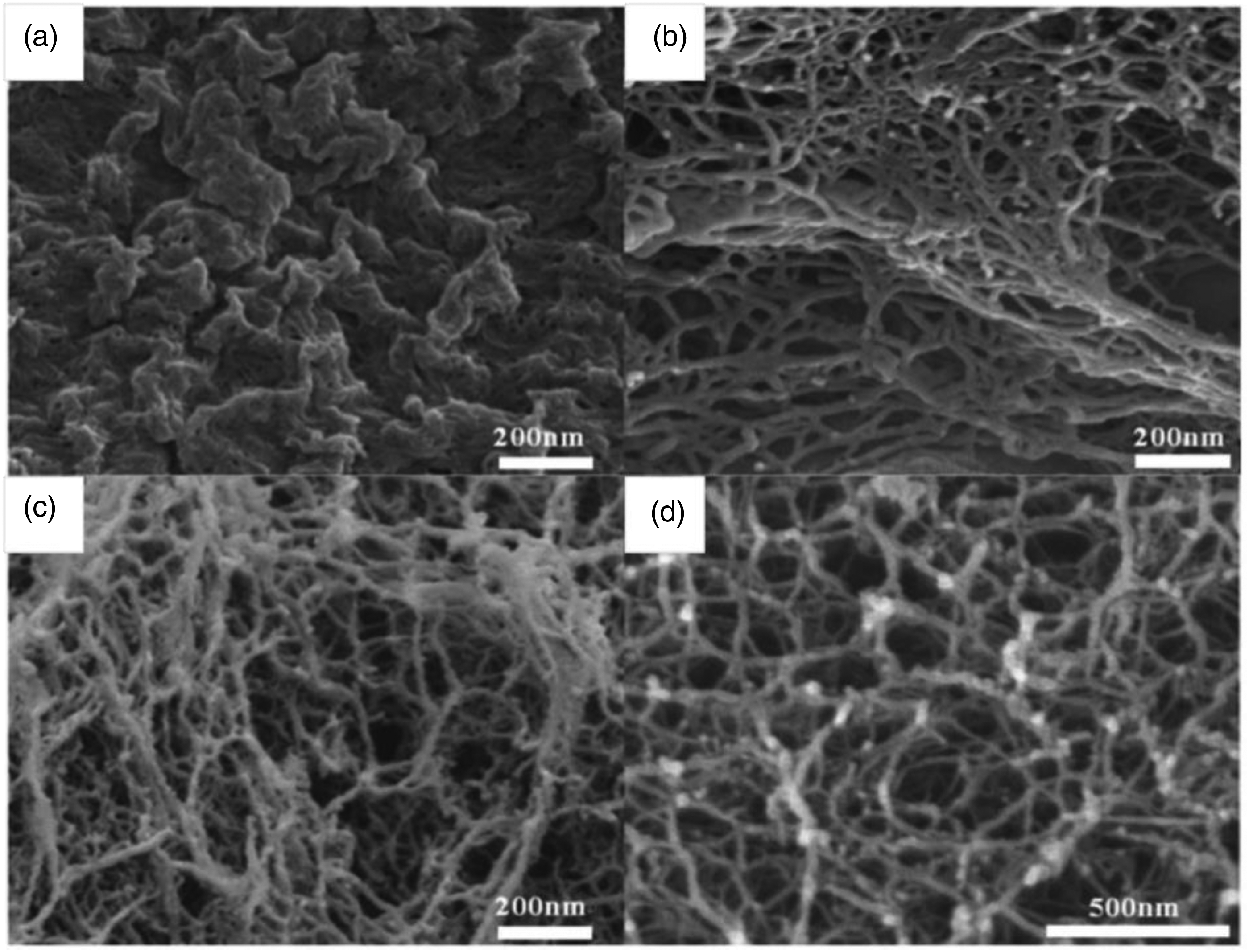
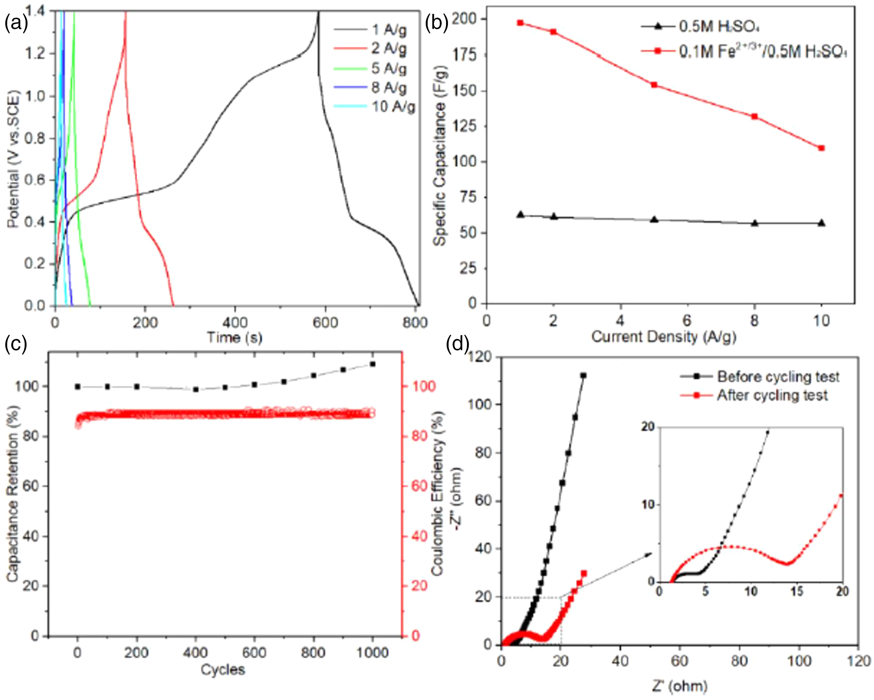
Meng et al.
130
electrodeposited branched PANI nanofibers with a diameter of 100 nm on Ti mesh substrate and molybdenum trioxide (MoO3) nanobelts with a width of 30–700 nm were obtained by the hydrothermal reaction method in an autoclave. To improve the electrochemical performance of the electrode nanomaterials, a redox-active electrolyte containing 0.1 M Fe2+/3+ redox couple was adopted. As a result, the PANI electrode showed a great capacitance of 3330 F g−1 at 1 A g−1 in 0.1 M Fe2+/3+/0.5 M H2SO4 electrolyte. The as-assembled asymmetric supercapacitor (ASC) achieved an outstanding energy density of 54 Wh kg−1 at a power density of 900 W kg−1. Furthermore, it displayed high cycle stability, and its capacitance even improved to 109% of the original value after 1000 charge-discharge cycles (Figure 18). (a) Galvanostatic charge/discharge curves of ASC at different current densities; (b) specific capacitance of ASC in different electrolytes; (c) capacitance retention and the columbic efficiency of 1000 cyclic test; and, (d) electrochemical impedance spectroscopy spectra before and after cycling test.
130
Wang et al. 109 prepared hierarchically branched TiO2/carbon nanofibers through a facile in situ synthesis route including electrospinning followed by an alkali hydrothermal treatment.
The branched TiO2/carbon nanofibers’ electrode delivers a stable capacity of 283.5 mAh g−1 at a current density of 200 mA g−1 after 1000 cycles and can still achieve 204.1 mAh g−1 even when the current density is raised to a very high rate of 2000 mA g−1 (Figure 19). They found that the free-standing hierarchically branched TiO2/carbon nanofibers can be served as anode materials for sodium-ion batteries (SIBs) and some other flexible electronic devices. Electrochemical performance of the BT/carbon nanofibers anode: (a) CV curves at a scan rate of 0.5 mV s−1. (b) Discharge/charge voltage profiles at a current density of 200 mA g−1 (c) Cycling performance at 200 mA g−1 and corresponding coulombic efficiency. (d)–(e) Charge/discharge profiles and rate performance obtained at various current densities.
109

Wang et al.
110
fabricated NBT/carbon@MoS2 nanofibers using electrospinning followed by hydrothermal treatment. They found that the NBT/carbon@MoS2 nanofibers deliver not only ultralong cycle stability (448.2 mAh g−1 after 600 cycles at 200 mA g−1) but also superior rate performance (258.3 mAh g−1 at 2000 mA g−1) (Figure 20). Therefore, the NBT/carbon @MoS2 nanofibers can be used as promising anode materials for high-performance SIBs. Sodium storage performance of NBT/carbon @MoS2 nanofibers. (a) CV curves at a scan rate of 0.5 mV s−1, (b) galvanostatic charge/discharge voltage profiles at a current density of 200 mA g−1, (c) cycling performance of NBT/carbon @MoS2 nanofibers in comparison with the NT/carbon @MoS2 nanofibers at a current density of 200 mA g−1, (d) charge/discharge profiles, and (e) rate performance obtained at various current densities.
110

Zhu et al.
108
synthesized successfully hierarchically branched TiO2@SnO2 nanofibers with tunable TiO2/SnO2 mass ratios via electrospinning followed by hydrothermal treatment. Their results showed the TiO2@SnO2 core-branch nanofibers with 30 wt% TiO2 exhibit both good rate capacity (378.3 mAh g−1 at a current density of 2.0 A g−1) and excellent cycling stability (453.3 mAh g−1 after 100 cycles at a current density of 500 mA g−1), suggesting they can be used as promising anodes for high-performance lithium-ion batteries (Figure 21). (a) Cycling performances of the ST1, ST2, and ST3 electrodes at a current density of 500 mA g−1 for 100 cycles. (b) Rate performances of the ST1, ST2, and ST3 electrodes at different current densities from 0.1 to 2 A g−1. (ST1, ST2, and ST3 represent composites consisting of 8 wt%, 18 wt%, and 33 wt% of TiO2, respectively.
108

Photocatalytic
This phenomenon is known as photocatalysis. Photocatalysis is a phenomenon, in which an electron-hole pair is generated on exposure of a semiconducting material to light. Photocatalysts are materials that alter the rate of a chemical reaction on exposure to light. 131
Wang et al. 120 provided a facile way to achieve controlled growth of rutile TiO2 nanowires over anatase nanofibers. The liquid–liquid interface promotes entrapment of precursor nanoparticles on the surface of nanofibers to yield ordered hyperbranched TiO2 heterostructures. Such unique heterostructures display higher photocatalytic performance in comparison with pure anatase TiO2 nanofibers and can be easily recycled. Branched TiO2 heterostructures show improved photocatalytic performance in comparison with the mixture of anatase TiO2 nanofibers and rutile nanowires, because of the synergistic effect by anatase/rutile heterojunction. Moreover, such branched TiO2 heterostructures are expected to open new opportunities for the fabrication of nanoscale electronic and photonic devices owing to their intrinsic complexity and dimensionality.
Nasir et al.
111
reported the fabrication of g-C3N4 QDs on the branched TiO2 fiber by a CVD method. The pure SnSe2 nanoflakes were also grown over this composition by the CVD method. They proved that SnSe2 nanoflakes were grown successfully and the synergetic effect of SnSe2 as a co-catalyst effectively decreases the charge recombination and provides an active site for the photocatalytic hydrogen performance (Figure 22). (a) Photocatalytic hydrogen performance of sample carbon nitride (CN), hierarchical branched TiO2 fiber after alkali hydrothermal treatment (HBT), HBTCN, HBT/CN/SnSe2, error bars are based on average data of three readings, (b) Cyclic test of the hydrogen performance of sample HBT/CN/SnSe2 up to 30 h.
111
(16).
Heat resistance
Aerogels are acknowledged for low thermal conductivity, high porosity, large specific surface area, and low density. These properties make them favorable for applications that required thermal insulation. The performance of hydrogels can be enhanced when they are in the nanoscale. Consequently, the branched structure has shown great potential in this field.
Li et al.
72
reported on biomimetic branched aramid nanofibers aerogels with the structure replicating articular cartilage, prepared by supercritical drying of 3D networks held together by hydrogen bonds. The aerogels exhibited high porosity with an average open pore size of 21.5 nm and a correspondingly low specific density of 0.0081 g/cm3. In addition, the aerogels showed a high compressive strength of 825 kPa at a strain of 80%. Because of the unique aramid chemistry of the parent nanofibers, aramid aerogels combine low thermal conductivity of 0.026 W/m•K with high thermal stability up to 530°C, which is unusually high for polymeric and composite materials of any type, opening a broad range of applications from electronics to space travel (Figure 23). Thermal conductivity of branched aramid nanofiber aerogels. (a) Thermal conductivity of branched aramid nanofibers aerogel 55 wt%. (b) Thermal conductivity of branched aramid nanofibers aerogel 50 wt%. (c) Thermal conductivity of branched aramid nanofibers aerogel 45 wt%. (d) Relationship between the concentrations of branched aramid nanofibers and Brunauer–Emmett–Teller method thermal conductivity in which the q″ of the Y-axis in (A), (B), and (C) mean the heat flux density. (e) branched aramid nanofibers aerogel was baked with a lighter flame for 5 min f, (g) Side view of aerogel.
72

Other applications
Branched nanofibers can also be used in many applications such as nano-coating, nano reinforcement, nanocomposite, nanomedicine, drug release, sensors for NO2, scaffolds, electronics, chemical sensors or actuators, gas-separation membranes, and neuron devices.72,106,107,113,114,116,130
Summary and future outlook
This paper reviews the materials, strategies, and applications of the branched nanofibers. A brief introduction of the branched nanofibers, material types, formation methods, characterizations, and applications of the branched fibers are discussed in detail. Based on our discussion, it can be concluded that: 1. A wide variety of materials can be used for producing a branched structure such as polyaniline, aramid, alumina, PI, PAN, TiO2/carbon, carbon, TiO2, a-MnO2, Te, TiO2@SnO2, PANI, PVDF. 2. Branched nanofibers can be obtained by different methods (electrospinning, chemical oxidative polymerization, solid-state reaction surfactant, calcination, CVD, interface-assisted synthesis, supercritical drying, and reflux). 3. Branched nanofibers have amazing properties (e.g., high surface area, tiny diameter, good piezoelectricity, excellent biological properties, outstanding mechanical properties, large porosity, excellent thermal insulation, and good thermal stability). 4. Branched nanostructure can serve successfully in many fields based on the material type (e.g., energy harvesting, air filtration, oil-water separation, energy storage, photocatalytic, nano-coating, nanocomposite, nano reinforcement, nanomedicine, scaffolds, drug release, and sensors for NO2, electronics).
In recent years, the branched structure has shown brilliant attainments in fundamental understanding and technological enhancements. About the future applications of branched structure, some vital issues need to be addressed: 1. Studying the effect of the formation methods on the branches degree and properties of the branched nanofibers. 2. Exploring the relationships between the material type and the branches degree as well as properties of the branched nanofibers. 3. Innovating new methods that can increase the branches degree of the nanofibers, resulting in enhancing their property. 4. Finding new applications of the branched nanofibers.
In summary, the branched structure of nanomaterials has the chance to be one of the promising demands of commercial companies. We hope that our dream about the golden age of the branched nanofibers will come to fruition soon.
Footnotes
Declaration of conflicting interests
The author(s) declared no potential conflicts of interest with respect to the research, authorship, and/or publication of this article.
Funding
The author(s) received no financial support for the research, authorship, and/or publication of this article.