
Abstract
Low intensity clashes have become the emerging crisis in society. In such situations, the protective vests worn by the law enforcing personnel are generally exposed to stabbing and low velocity impact from splinters. The present study is an attempt to explore the potential of Ramie, a natural fibre, to be used in body armours designed for relatively lesser threat (compared to military operations) encountered in low intensity conflict areas. Cultivation of Ramie plant to the preparation of Ramie fabric – the entire process is performed in a laboratory setup. Experiments (uniaxial tension test, direct shear test, yarn pull-out test, etc.) are conducted to characterize the stress–strain behaviour and inter-yarn friction of Ramie. The ballistic responses of single and multi-layered Ramie fabric targets are numerically investigated via FEM. In order to understand where Ramie stands with respect to Kevlar (a commonly used para-aramid synthetic fabric), the response of a single layer Kevlar target under similar circumstances (i.e. target size, boundary conditions, projectile types and impact velocities) is taken as the benchmark. Through the series of numerical simulations, the advantage and limitations of Ramie vis-a´-vis Kevlar are brought to an extent.
Introduction
Bulletproof or bullet-resistant vest is a personal level armour system. It is generally used to protect the human torso from the threat of bullet impact, blast or stab. At different times in history, different materials have been used in body armours depending upon the nature of threats. In the present time, modern military operations, technology-driven war tactics, and current on street weapons and ammunition demand a flexible, damage-resistant, and lightweight ballistic protection garment with superior energy absorbing capacity. Para-aramid fabrics1–5 such as Kevlar, Twaron, Spectra, Dacron and Dyneema possess such characteristics and therefore are widely used in protective vest with different threat levels.
These para-aramid fabrics are prohibitively costly. Owing to the high cost, their use is mostly restricted to armours subjected to medium to high velocity impact commonly encountered in military operations. However, due to the increasing activities of extremism, today society also needs to provide protection to its police forces, security staff, correction officers where the wearer is subjected to impact from stab and bullet (or any other free flying object, that is, splinters) with low velocity. Therefore, there is a great need to identify new materials that would be cost-effective, locally available and friendly to the human body. In this context, it would be interesting to investigate whether natural fibres could be a potential alternative to the conventional material for use in body armour subjected to low threat.
Wambua et al. 6 were probably the first to consider natural fibres for ballistic applications. Since then, some studies were carried out to explore the ballistic performance of different natural fibres, namely, jute,6–9 malow,8,10,11 coir, 12 cocos nucifer shealth, 13 piassava, 14 sisal,15,16 curaua17–21 and Ramie.22–31
Ramie (Boehmeria nivea) is one of the strongest natural cellulose fibres and comes with good physical and mechanical properties holding a great promise to be an alternative for protective vest subjected to low threat level. Even a partial replacement of Kevlar may reduce the cost substantially since Ramie can be procured locally and at a very nominal cost. In 2009, Marsyahyo et al. 22 were perhaps the first to use Ramie fibres for the development of fibre-reinforced polymer bullet proof panels and experimentally identify the potential of Ramie in armour applications. Anggoro and Kristiana 25 also performed experimental study on multi-layered target made of Ramie fibres. Monteiro et al. 26 studied the comparative performance of Ramie and Kevlar in multi-layered armour system (MAS) where fibre-reinforced composite panels were sandwiched between ceramic plate at the front and aluminium plate as backing. From the experimental observation, they identified that 30 vol.% Ramie–epoxy composite could replace the traditional Kevlar–epoxy composite backing plate keeping the thickness same. They also reported that MAS with Ramie–epoxy composite costs almost half that of MAS with Kevlar. Braga et al. 27 also performed similar experiment and reported the benefit of using Ramie–epoxy composite in MAS over epoxy–aramid composites.
The existing literature22–31 is mainly focused on using Ramie–epoxy composite hard panels along with ceramic and metal plates in MSA. Despite being promising amongst all natural fibres, Ramie has not yet been explored in flexible body armour. In the present study, behaviour of Ramie fabric under projectile impact is investigated and its performance (in terms of out-of-plane deformation and energy dissipation) vis-a´-vis Kevlar is assessed. The present study involves several tasks such as cultivation of Ramie plant, extraction of fibres from the plant, preparation of yarn and fabric from the extracted fibres, determination of mechanical and frictional properties of Ramie through experiment, and finally finite element modelling of single and multi-layered Ramie fabric under projectile impact. For a better assessment of the ballistic performance of Ramie vis-a´-vis Kevlar, similar simulations are also performed with Kevlar target. In the FEM model, the individual yarn in the fabric is idealized as a strip of membrane elements preserving the yarn crimp and then multiple yarns in both directions (warp and weft) are combined to comprise the fabric. Through the numerical simulations, the ballistic performance (both dynamic displacement and failure) of Ramie with different numbers of fabric layers are estimated and compared with the response of single layer Kevlar target. Finally, the number of Ramie layer required to obtain the similar ballistic performance of single layer Kevlar is identified and the feasibility of using Ramie in low threat protective vest is discussed.
Preparation of material
Preparation of Ramie fibre
Ramie fibres used in the present study are prepared from Ramie plants (Figure 1) cultivated in IIT Kharagpur campus, India. Fibre preparation involves mainly decortication, degumming and bleaching processes.
32
Details of these processes are given below. Ramie plants.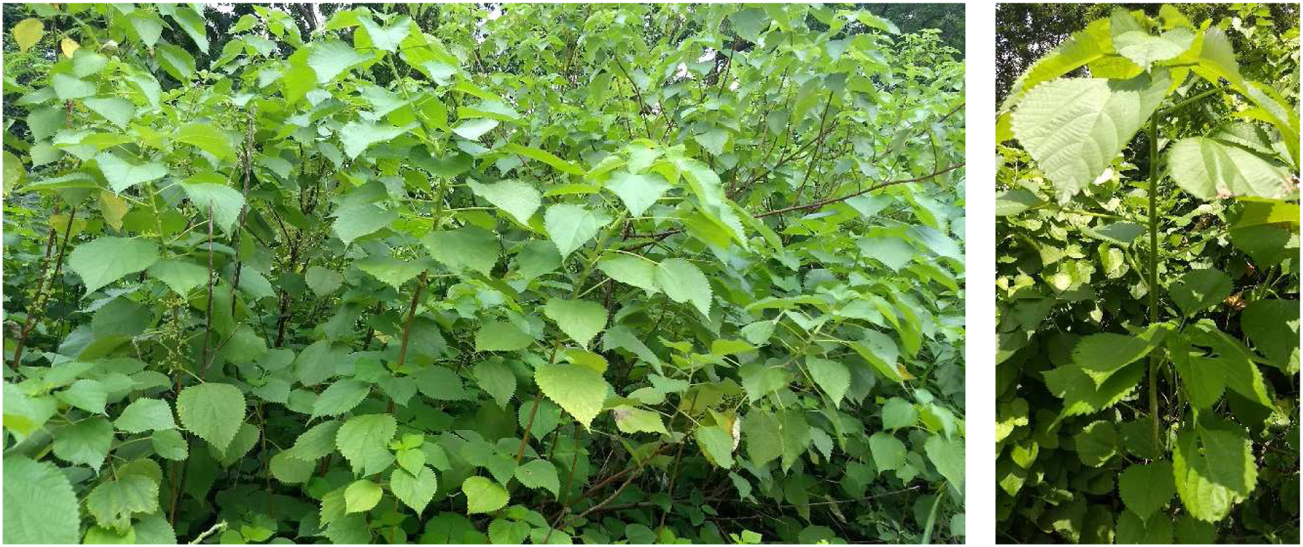
Decortication is the process of extracting ribbons from the plants. A prototype mechanical decorticator machine (Figure 2(a)) is developed and used to extract ribbons (Figure 2(b)) from matured Ramie plants which are approximately 60 days old.
33
The decorticated ribbons are further processed to prepare usable Ramie fibres. Decortication of Ramie plant and decorticated ribbons. (a) Decortication using Decorticator machine. (b) Decorticated ribbons.
In the degumming process,34,35 the decorticated ribbons are squeezed by passing them through a serrated two-roll machine (Figure 3). This process removes a major part of gum from the raw fibres by squeezing. After this, the final degumming of the fibres is done through chemical treatment. In the chemical degumming process, initially the squeezed Ramie fibres are soaked in 10% NaOH solution (100 gm fibres in 1 litres of solution) for 24 h. Then the soaked fibres are boiled at 120°C for 3–4 h in the caustic soda solution (Figure 4). After degumming, the fibres are washed thoroughly with water to neutral pH, dried and conditioned at 30°C and 65% relative humidity. Finally, the degummed fibres are bleached using 10% sodium chlorite solution at pH 4 (Figure 5) for a period of 12–16 h. These concentrations and temperature are selected based on few trials so as to remove the gum from the decorticated Ramie plant considered in the present study. The parameters may vary depending on the species and the age of the plant. A flow diagram showing different processes involved in the Ramie fibre preparation is shown in Figure 6. Partial degumming by squeezing and Ramie fibre after squeezing. (a) Partial degumming by squeezing. (b) Ramie fibre after squeezing of gum. Chemical degumming by boiling in chemical solution and Ramie fibre after chemical degumming. (a) Degumming by boiling in chemical solution. (b) Ramie fibre after chemical degumming. Bleaching of Ramie fibres and bleached Ramie fibres. (a) Bleaching of Ramie fibres. (b) Degummed and bleached Ramie fibres. Different processes involved in the Ramie fibre preparation.


Preparation of Ramie yarn
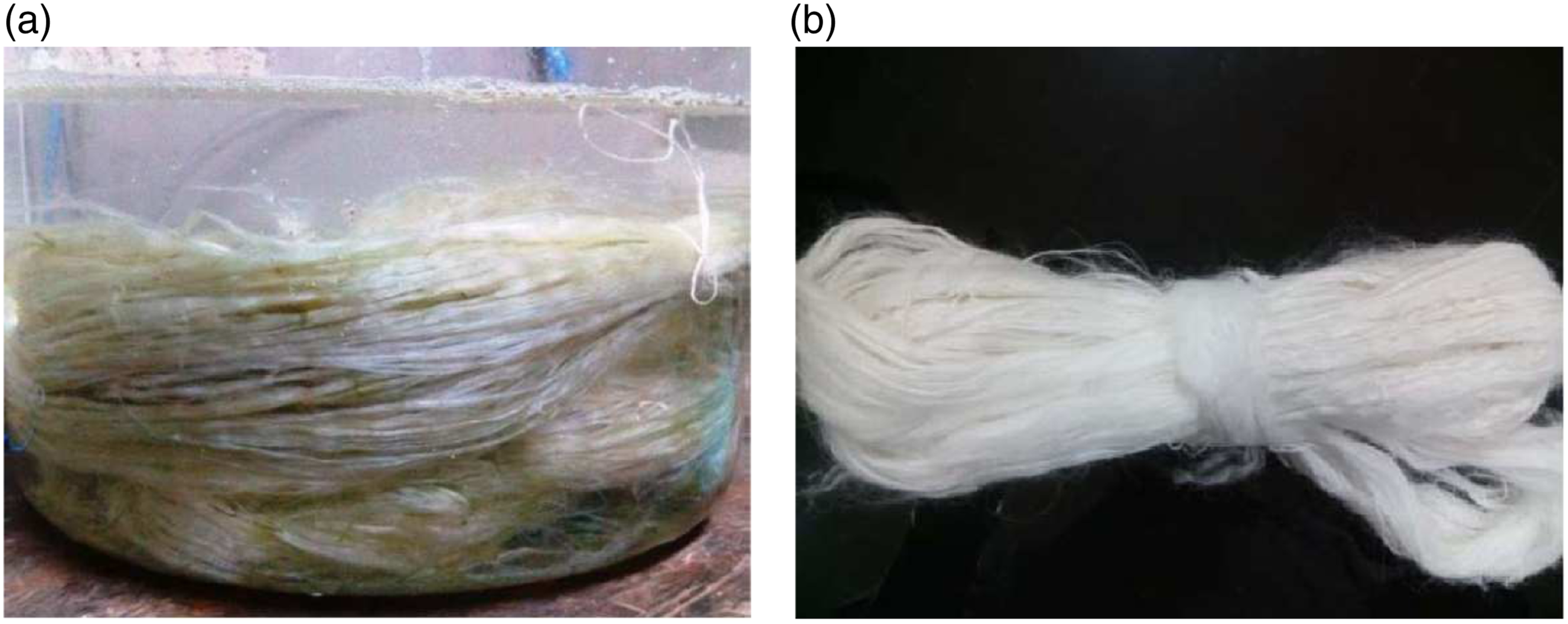
Hand spun yarns are prepared by integrating several Ramie filaments. Spindle (Figure 7(a)) is used to apply the twist in the filaments. Figure 7(b) shows the prepared yarns from the degummed and bleached Ramie fibres. Diameters of the yarns are measured using optical microscope and the average diameter is found to be approximately 1.2 mm. Hand spun yarn of degummed and bleached Ramie fibre. (a) Spindle. (b) Ramie yarns.
Preparation of Ramie fabric
Ramie fabrics (Figure 8) used in the present study are prepared using the hand spun yarns. The fabric is manually weaved by piling warp and weft yarns in a rectangular pattern where warp yarn alternatively passes over and under the weft yarns. Geometric details of crimp in the prepared Ramie fabric are measured using optical microscope. Average wave length (λ) and crimp height (h) are found to be 4 mm and 0.6 mm, respectively. Plain woven Ramie fabric.
Material characterization of Ramie
Tensile testing of Ramie fibre
Tensile test specimens are prepared with the Ramie filament. Each specimen has a gauge length of 25 mm with 25 mm grip on both sides (Figure 9(a)). Experiments are carried out using the Universal Testing Machine Tinius Olsen H10K-S (Figure 9(b)) as per ASTM D3822-01
36
with a constant speed of 0.5 mm/min. Proper measurement of filament’s diameter is very important for estimation of tensile stress. For each filament, first diameters are estimated at several locations (Figure 10) using optical microscope and then the average value is taken for further calculations. Tensile test of Ramie fibre in UTM and tensile test specimen. (a) Tensile test specimen. (b) Tensile test of Ramie in UTM. Ramie fibre’s diameter measurement using optical microscope.

Experimentally obtained stress–strain behaviour for few representative test cases is shown in Figure 11. From the experimental results, it may be observed that the Ramie fibre behaves in a linear elastic manner. After reaching the maximum stress, the fibre breaks suddenly without going through any noticeable plastic deformations. Experimentally obtained stress–strain behaviour of Ramie fibre.
Mechanical properties of Ramie fibres.

Frictional behaviour
Apart from the stress–strain behaviour, inter-yarn friction plays a very important role in the dynamic behaviour of any woven fabric. The inter-Ramie friction is estimated through Direct Shear test (IS: 2720 (Part 13).
37
) as illustrated in Figure 12. The test comprises a shear box (6 cm × 6 cm cross section) with two parts having a horizontal separation plane. The test specimens are prepared by wrapping two wooden blocks with Ramie yarn (Figure 12(c)). Dimensions of the wooden blocks are taken in such a way that after wrapping with Ramie yarn, the test specimens fit in the shear box and the plane between two specimens coincides with the separation plane. The two blocks are made to slide horizontally by the action of steadily increasing horizontal force while a constant load is applied normal to the plane of relative movement. Direct shear test of Ramie fibre. (a) Direst shear test apparatus. (b) Schematic diagram of direct shear test. (c) Direct shear test specimen.
The direct shear tests are performed for three different normal forces, namely, 180 N, 360 N, and 720 N. Figure 13a shows the variation of applied horizontal force with the horizontal displacement of top box. In order to determine the frictional coefficient, maximum horizontal force is plotted corresponds to the applied vertical force in Figure 13(b) and the best fit straight line is drawn. The slope of the base fit curve gives the frictional angle (φ) and it is found to be 18.5°. The coefficient of friction between Ramie yarns is then obtained as μ = tan φ = 0.33. Inter-Ramie frictional behaviour. (a) Horizontal displacement versus horizontal force. (b) Vertical load versus maximum horizontal force.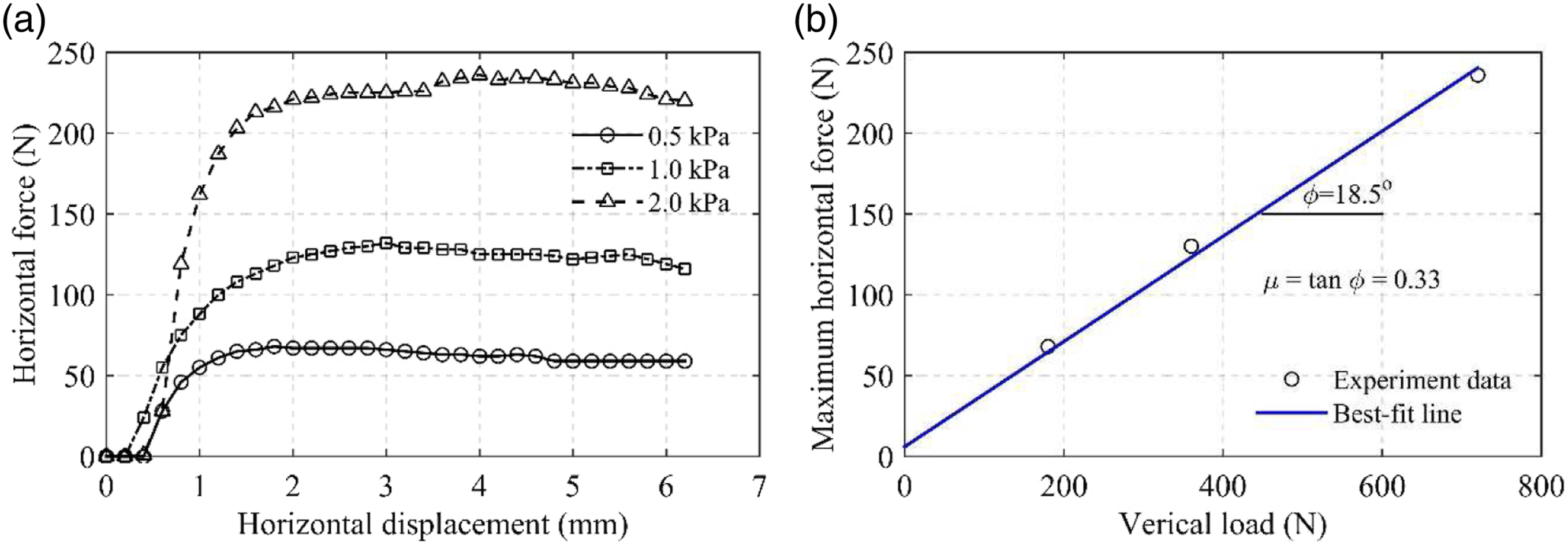
Geometrical and material properties of Kevlar
Kevlar is the most widely used synthetic fibre in body armour applications. Therefore, it is important to understand where Ramie stands vis-a´-vis Kevlar in terms of ballistic performance (numerically simulated in Ballistic response of Ramie). The properties of Kevlar are taken from the available literature and the same are summarized in this section for ready reference.
Geometric attributes of Kevlar
The style of Kevlar fabric considered in the present study is K-706, which contains plain woven 600 Denier KM2 yarns. The yarn density of the fabric is 34 yarns per inch. Typically, each yarn consists of nearly 400 filaments each of diameter 12 μm and density 1440 kg/m3.38–40 Schematic diagram of cross sections of the fabric is shown in Figure 14 and the dimensions of cross section are given in Table 2. Schematic diagram of cross sections of the fabric.
66
Dimensions of the cross section of Kevlar KM2 fabric.
39


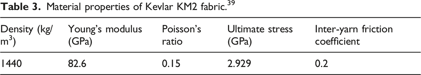
Material properties of Kevlar KM2 fabric
Material properties of Kevlar KM2 fabric. 39
Yarn pull-out test
Yarn pull-out tests of manually prepared plain woven Ramie fabrics (Figure 8) are carried out to understand the inter-yarn friction behaviour in the fabric structure. Test set up is shown in Figure 15. The fabric specimen is fixed in a U-shaped frame, where the weft yarns are clamped at both the ends. In this configuration, warp yarns are allowed to move through the fabric specimen. Bottom of the U frame is fixed to the bottom grip of universal testing machine (UTM) while one innermost warp yarn is fixed to the other grip. This inner most warp yarn has an extended length of 20 mm as shown in Figure 15(b). The warp yarn is pulled in upward direction with a constant speed of 5 mm/min till it completely comes out of the fabric. The force–displacement curve obtained from the pull-out test is shown in Figure 16. Experimental set up for pull-out test of Ramie fabric. Load–displacement curve obtained from pull-out test.

During the pull-out test, both fabric and the pulled yarn go through different stages of deformation. At the initial stage, the fabric experiences in-plane deformation. During the in-plane deformation, no relative movement between the yarn and fabric takes place. Once the in-plane deformation reaches its maximum value, the warp yarn undergoes uncrimping and straightening. During these two deformation stages, pull-out force gradually increases with displacement. Pull-out force reaches its maximum value when the pulled yarn becomes almost straight. After this, the relative movement of yarn with respect to the fabric starts to take place. At the starting of relative movement, the pull-out force suddenly drops as the resisting frictional force changes its nature from static to kinematic friction. After this, the warp yarn crosses the weft yarns and comes out completely from the fabric at the end of the experiment. During this stage, the pull-out force gradually reduces as the number of resistive weft yarn crossover reduces. Pull-out force takes a value zero when the warp yarn completely comes out from the Ramie fabric.
Force–displacement curve obtained from the pull-out test of Ramie fabric is shown in Figure 16. Das et al. 39 performed pull-out test of Kevlar fabric. Therein, the size of the fabric was taken as 120 mm × 119 mm and the tail length of pulled yarn was taken as 80 mm. For a given fabric (weave architecture and inter-yarn friction), the total pull-out force can be taken 41 as a linear function of embedded yarn length (which is a measure of number of crossover points). Therefore, the result of Das et al. 39 is linearly scaled as per the present dimension of fabric and the same is compared with the force–displacement curve of Ramie fabric in Figure 16. Pull-out force obtained for Ramie fabric is found to be much higher as compared to the pull-out force of Kevlar fabric. This enhancement in behaviour may be resulted due to the higher inter-yarn friction (0.33 for Ramie as compared to 0.2 for Kevlar) in Ramie fabric. In Figure 16, non-smooth variation of force–displacement curve for Ramie fabric is observed. This may be ascribed to the non-uniformity in weaving of manually prepared Ramie fabric (Figure 8)
Computational framework for modelling fabric structure subjected to projectile impact
Idealization and FE discretization
In the existing literature, fabric structures are generally modelled using two different approaches, namely, fabric level continuum model and yarn level continuum model. In the first approach, the entire fabric is considered as a continuum and modelled using membrane, shell or solid elements.42–49 This is comparatively simpler and less computationally intensive, but cannot incorporate several dominating deformation mechanisms (namely, in-plane yarn motion, yarn unravelling, inter-yarn interaction and yarn-projectile interactions) associated with the impact response of fabric structures. In the second approach, each yarn is idealized as continuum. This approach provides a better representation of fabric structures. In the available literature, different elements (namely, pin-jointed bar element, shell element, 3D brick element, etc.) are used to model the yarns (both warp and fill). Among them, pin-jointed bars39,50–52 have the least computational cost. Though the truss model is relatively simpler and capable of presenting the overall fabric response but fails to properly incorporate the interactions between fabric layers, which is an important aspect in multi-layered fabric targets. Numerical models developed using 3D solid element considering actual weave geometry and effect of inter-yarn friction53–55 are undoubtedly accurate, but computationally intensive. Moreover, the material parameters for the constitutive behaviour adopted in those models, such as orthotropic (nine independent parameters) and transversely isotropic (five in-dependent parameters), can only be determined using sophisticated experimental setups. Attempts are also made to model individual filament 56 with solid brick elements 57 to study the energy dissipation mechanism at micro scale. However, this is computationally infeasible and also may not be required in macro-scale simulation.
All the computational models mentioned above have their own share of advantages and limitations. Choice of a particular model is governed by several factors such as information about the constitutive and interaction parameters, scale of the model under consideration, expected response and availability of computational resources. In the present study, a yarn level membrane-based finite element model (similar as of Sen et al.
66
) is developed using ABAQUS.
58
A single yarn is modelled as a strip of membrane elements and then multiple yarns are combined to comprise the fabric as illustrated in Figures 17 and 18. Yarn geometry is meshed using the ABAQUS finite element M3D4R (four nodded membrane element with reduced integration). Numerical membrane element model for single layer Kevlar fabric with cylindrical bullet (RCC). Numerical membrane element model for single layer Ramie fabric with cylindrical bullet (RCC).

Incorporation of membrane element for discretization the yarn geometry eliminates the rotational degree of freedom and only three translational degrees of freedom remain active. This representation (using membrane element) neglects the contribution of the small bending stiffness of the yarns. This approximation reduces the computational cost without compromising the accuracy of ballistic performance measurement parameters (back-face deformation and residual velocity) under consideration. Modelling of multi-layered fabric target system (as shown in Figure 19) involved more than one number of plies stacked in same orientation. Geometric details of crimp in Ramie (manually woven) and Kevlar fabric are given in Preparation of Ramie Fabric and Geometric Attributes of Kevlar, respectively. Projectile is modelled as rigid body due to the high relative stiffness of steel projectile with respect to the fabric material. Isometric view of multi-layered Ramie fabric system.
Inter-yarn and inter-fabric interaction
Interactions between yarns at crossovers and between the projectile and the fabric are assigned using the general contact algorithm available in ABAQUS. All the contact tangential behaviours are modelled with Coulomb friction. In case of multiple-layered fabric targets, the same contact algorithm is also used to incorporate the inter-fabric interaction so that the model is able to simulate the stress waves propagating through multiple fabrics from the impact point. For Ramie and Kevlar targets, the frictional coefficients are taken as 0.33 (as determined through Direct Shear test in Frictional behaviour) and 0.2, 39 respectively.
Material model: Strength and failure
Fibre materials, considered in the present study (i.e. Kevlar and Ramie), follow a linear stress–strain behaviour up to ultimate strength and then break suddenly. In the present computational model, yarn material response is also characterized through the same stress–strain behaviour. Accordingly, each membrane element follows a linear elastic stress–strain path up to the ultimate strength beyond which, the element is assumed to be fully damaged and therefore removed from the system. Mechanical properties of Ramie and Kevlar are given in Tables 1 and 3, respectively. The damage is defined through fracture energy-based criteria where small amount of fracture energy capacity (equivalent to 0.01% strain beyond the elastic limit) is assigned to the membrane elements. Density of ramie fabric is taken as 1500 kg/m3. 22
Validation of computational model
In this section, the computational model for fabric structure described in the previous section is validated using the experimental results reported in the literature. Yu et al.
59
carried out several experiments on single layer Kevlar target for different projectile shapes and muzzle velocities. Results of the few representative test cases from their large experimental database are taken to validate the present computational model of fabric structure. Herein, the behaviour of a 177.8 × 177.8 mm2 single layer plane woven fabric fixed on a circular (50.8 mm diameter) steel holder as depicted in Figure 20 is considered. Results for two different projectile types, namely, (a) stainless steel right circular cylinder (RCC, diameter = 5.51 mm, length = 5.50 mm, mass = 1.027 g, SS type 440C) and (b) 0.22 CAL fragment-simulating projectile (FSP, 0.22 CAL, 1.1 g, MIL-P-46593A) are taken as reference experimental data. Fragment-simulating projectile (FSP) of 22 Cal. 1.1 g is modelled with the dimensional specifications given in Ref. 60. Herein, the Kevlar fabric is modelled with a thickness of 0.23 mm and a yarn crimp wavelength of 1.548 mm as reported in Ref. 39. Rigidly held condition at the support (as in experiments) is simulated by restricting the displacements of the support nodes in all Degree of Freedoms (DoFs). Schematic diagram of Kevlar target and projectile system.
First, the deformation time histories of impact point are compared (Figure 21) with the reference experimental results for different muzzle velocities. In both projectile cases, the impact velocities are considered in such a way that, for two comparatively lower velocities, projectile bounces back from the target and for the higher impact velocity, penetration takes place. In all considered cases, numerically obtained displacement time histories at the impact point show a good agreement with their experimental counterparts. In case of non-penetrating velocities, numerically obtained displacement time histories in post peak region are also in line with the experimental observations. Comparison of time histories of displacement at the impact point. (a) Projectile: RCC. (b) Projectile: FSP.
While deflection is an important measure of the response of any structural system, the representation which is frequently used in most designs to characterize the overall capacity of a structure in resisting impact loading is the ballistic limit curve. For a given projectile/target system, it is the plot of residual versus initial/impact velocities of the projectile. The abscissa intercept of the curve provides a deterministic estimate of the limit velocity, that is, the maximum velocity at which all impact energy is absorbed by the target and no failure takes place. Numerically obtained ballistic limit curves for both the projectile cases are compared with the experimental data
59
in Figure 22 In the ballistic limit curves, the negative residual velocities represent the test cases where projectile rebounds from the target, whereas the positive residual velocity represents the penetration of the target by the projectile. Close agreement between the numerical prediction and the experimental observations (Figures 21 and 22) illustrates the efficiency of the present numerical model. Further validation of the computation model for multi-layer fabric structure can be found in the earlier study by the authors.
66
Comparison of residual velocities of projectile. (a) Projectile: RCC. (b) Projectile: FSP.
Ballistic response of Ramie
In this section, the response of Ramie fabric under projectile impact is numerically investigated through the computational framework discussed in Computational framework for modelling fabric structure subjected to projectile impact. The purpose is to examine the performance of single and multi-layered Ramie targets vis-a´-vis single (1L) layer Kevlar target, and in the process understand whether Ramie is a viable option in replacing Kevlar in low-cost protective vest. Towards this, the performance is characterized by three parameters, namely, out-of-plane deformation, limit velocity and weight of the target. In case of Ramie, three different target configurations, namely, single layer (1L), two layers (2L) and three layers (3L) are considered. The lateral dimensions of the target, boundary conditions, and mass and shape of the projectiles (RCC and FSP) are kept same as considered for validation in the previous section.
In the literature, there exist some experimental and numerical studies61–65 to understand the effects of weave architecture on the ballistic performance of fabric. These studies suggest that for a given setting, that is, yarn denier, areal density and yarn count, plain woven fabric absorbs more energy compared to its other counterparts. Moreover, for multi-layer fabrics, ballistic performance is less influenced by the weaving architecture. Therefore, only plain woven fabric is considered in the present study.
Numerically obtained ballistic limit curves for different Ramie targets (i.e. 1L, 2L and 3L) are compared with experimentally
59
and numerically obtained 1L Kevlar target in Figure 23 For RCC (Figure 23(a)), it is observed that 1L and 2L Ramie targets have lower limit velocities (55.7 m/s and 94.8 m/s, respectively) compared to the 1L Kevlar target (110.6 m/s). The computed limit velocity of 3L Ramie target (121.3 m/s) is higher compared to the 1L Kevlar target. Similar behaviour is also observed in case of FSP as shown in Figure 23(b). For FSP, the limit velocity of 3L Ramie target is found to be 119.2 m/s which is higher than 1L layer Kevlar target (91.2 m/s). The comparison of limit curves shows that 1L Kevlar may be replaced with 3L Ramie to produced similar level of penetration resistance. Comparison of residual velocities of projectile. (a) Projectile: RCC. (b) Projectile: FSP.
Maximum displacement (in mm) of Kevlar and Ramie targets impacted by RCC.

Maximum displacement (in mm) of Kevlar and Ramie targets impacted by FSP.


Time evolution of mid-point displacement of Kevlar and Ramie targets impacted by RCC. (a) V0 = 39 m/s. (b) V0 = 60 m/s.

Time evolution of mid-point displacement of Kevlar and Ramie targets impacted by FSP. (a) V0 = 39 m/s (b) V0 = 48 m/s.

Deformed configuration of Kevlar and Ramie targets impacted by RCC with impact velocity V0=123 m/s. (a) Single layer Kevlar target (at t=100 µs). (b) Single layer Ramie target (at t=125 µs). (c) Two-layer Ramie target (at t=180 µs). (d) Three-layer Ramie target (at t=190 µs).

Deformed configuration of Kevlar and Ramie targets impacted by FSP with impact velocity V0=98 m/s. (a) Single layer Kevlar target (at t = 130 µs). (b) Single layer Ramie target (at t = 210 µs). (c) Two-layer Ramie target (at t = 240 µs). (d) Three-layer Ramie target (at t = 255 µs).
Percentage of impact energy is dissipated through frictional dissipation in Kevlar and Ramie targets impacted by RCC.

Percentage of impact energy is dissipated through frictional dissipation in Kevlar and Ramie targets impacted by FSP.


Frictional dissipation of Kevlar and Ramie targets impacted by RCC and FSP with impact velocity V0=39 m/s. (a) Projectile: RCC. (b) Projectile: FSP.
Along with the above-mentioned ballistic performances, weight of any armour materials is also important for movability of any wearer. Weight of unit square metre single layer Ramie fabrics (used in the present study) is found to be 0.45 kg. The same weight for single layer Kevlar is around 0.17 kg. From the weight comparison, it can be identified that equivalent Ramie target will have higher weight in comparisons to Kevlar target.
Conclusions
The possibility of using Ramie (a natural fibre) in low-cost protective vest is examined in this study. The material processing involves cultivation of Ramie plant, extraction of fibres from the plant, preparation of yarn and fabric from the extracted fibres. The entire process is performed in a laboratory set up so as to minimize the variation in material properties commonly encountered in natural fibres. Experiments are conducted to determine the mechanical (strength and failure) and frictional properties of prepared Ramie fibres. Finally, ballistic responses of single and multi-layered Ramie fabrics are numerically investigated via FEM. In the numerical model, every yarn in the fabric is idealized as a strip of membrane elements preserving the yarn crimp and then multiple yarns in both directions are combined to form the fabric. Projectiles are modelled as rigid body. Simulations are performed with different projectiles, impact velocities and also with different number of Ramie fabric layers. The response of a single layer Kevlar under similar circumstances is taken as the benchmark to assess the relative performance of Ramie. It is observed that in terms of both limit velocity and maximum out-of-plane displacement, target comprising three layers of Ramie fabric shows similar or better behaviour to that of single layer Kevlar target.
Strength to weight ratio is an important parameter that govern the choice of materials for body armour. Ramie is denser than Kevlar, and moreover, due to the requirement of more number of fabric layers (to match the performance of single layer Kevlar), armours made of Ramie will be bulky and heavier than that of Kevlar. However, when used for low threat level (which is the objective here), it is anticipated that the total number of Ramie fabric layers may not be unreasonably high and therefore not cause discomfort to the wearer. Partial replacement of Kevlar by Ramie may also be a way out to maintain a balance between strength and weight.
The results presented here show that Ramie has potential to be an alternative to the conventional synthetic fibres for use in body armours subjected low threat. Further investigation is required to use Ramie in the most effective way in practical applications. Thermal property and durability of Ramie are some other important aspects that need to be studied. These may constitute the content of future work.
Footnotes
Declaration of conflicting interests
The author(s) declared no potential conflicts of interest with respect to the research, authorship, and/or publication of this article.
Funding
The author(s) received no financial support for the research, authorship, and/or publication of this article.