
Abstract
3D knitted fabrics are regarded as a viable option for advanced composite materials. Flat-knitted spacer fabrics (FKSF) which are in the category of 3D knitted structures have attracted many attentions due to outstanding characterizations such as high formability and good impact behavior. These structures consist of two surface layers which are linked together by multiple knitted connecting layers. Despite the merits of 3D-FKSFs as composite reinforcements, they have some structural restrictions such as limited thickness. This study aims to develop and characterize bi-directional 3D knitted spacer structures which could be replaced with conventional FKSFs. In the developed structures, the upper and lower surface layers are connected together by two truncated pyramids which can be configurated in any dimensions using an innovative knitting technique. For providing a report regarding their compression behavior, these 3D structures were produced in two different thicknesses on an electronic flat knitting machine. Then, they were impregnated with epoxy resin via vacuum resin transfer molding and the cured composites were subjected to compression force. The results revealed that their compression behavior is similar to the behavior of conventional honey-comb sandwich structures.
Keywords
Introduction
In recent years, 3D textile-reinforced composites have attracted many attentions due to outstanding characterizations such a structural integrity and high mechanical performances [1,2]. Nowadays, 3D textile reinforced composites are used in various fields including aerospace (aircraft framework, aircraft airfoils), construction (I-Beams, concrete), automotive, biomedical (prosthesis) and so on. Among the various production techniques such as braiding, knitting and weaving, weft-knitting technology demonstrates high potential in designing 3D structures with complex geometrical shapes [3–5]. This ability is due to technical advancements of flat knitting technology such as CAD designing, individual needle selection capability, fully fashioning knitting, stitch pressing-down device and needle-bed racking. 3D-flat-knitted spacer fabrics (3D-FKSF) could be produced with various cross-sectional shapes on modern flat knitting machines. Figure 1 depicts cross sectional views of these 3D structures. 3D-FKSFs could be used as composite reinforcement in various areas such as automotive and aerospace industries and environmental protection [5]. Moreover, these 3D structures could be an appropriate replacement for sandwich-structure composites in which the de-lamination phenomenon is mostly appeared.

Cross sectional views of different 3D-FKSFs [6].
Several investigations have been conducted on mechanical properties of the composites reinforced with 3D-FKSFs. Abounaim et al. [5] fabricated thermoplastic composites reinforced with 3D-FKSFs in rectangular cross-sectional shape using glass/polypropylene commingled yarns. Hamedi et al. [7] simulated bending behavior of thermoset composites reinforced with 3D-FKSFs using multi-scale finite element method. Hassanzadeh et al. [6,8–11] produced 3D-FKSFs with different cross-sectional shapes and investigated the effect of fabric cross-section on bending and compressive characteristics. They reported that the fabric cross-sectional shape has significant effect on mechanical performance of the produced composites thereof.
Omrani et al. [12,13] produced tubular composites reinforced with 3D-FKSFs and investigated their behavior in terms of external static and internal hydrostatic pressures. The effect of cross-sectional shape of glass-epoxy composites reinforced with 3D-FKSFs on their low-velocity impact behavior using drop weight impact test was investigated by Azadian et al. [14,15]. They concluded that the cross-sectional shape significantly affects the low-velocity impact behavior of the produced composites. Hosseini et al. [16] investigated the effect of core geometry and reinforcing the surface layers on bending behavior of 3D flat-knitted spacer composites. Also, Abedzade et al. [17] concluded that the core geometry has significant effect on free vibration of the composites reinforced with flat knitted spacer fabrics.
From Figure 1, it should be stated that 3D-FKSFs are composed of two surface layers which are connected together by multiple knitted connecting layers. According to literature [9] the surface layers are knitted on odd needles of the rear and front needle-beds while the connecting layers are knitted on even needles. This means that the odd needles should be inactive when a specific connecting layer is being knitted. Therefore, length of the connecting layers as well as fabric thickness will be restricted because the odd needles cannot remain inactive for a long time. This limitation can affect the range of their industrial applications.
The present paper aims to introduce a bi-directional 3D knitted spacer structure which can be produced in any dimensions. The introduced structures have more complicated core geometry in comparison to conventional 3D-FKSFs. They are composed of upper and lower surface layers which are connected together by two hollow truncated pyramids. The previous investigations [10,15] conducted in field of 3D knitted flat knitted spacer reinforced composites revealed that not only resin characteristics but also the structural geometry have significant effects on their compression and low-velocity impact behavior. For providing a report regarding their compression behavior, these 3D knitted structures were produced in two different thicknesses. Then, they were impregnated with epoxy resin via vacuum resin transfer molding. Compressive properties of the produced composites were investigated.
Materials and methods
3D fabric production
3D knitted fabrics were produced on an electronic flat-bed knitting machine (Stoll CMS 400, E5) using 300-Tex high tenacity Nylon yarns. The tensile properties of a single strand were evaluated by Zwick tensile tester (model 1446-60) according to ASTM D2256 standard. Table 1 presents the properties of the yarn used.
Yarn mechanical properties.

Figure 2 demonstrates the newly designed 3D knitted structure which has been produced in current research. This structure consists of upper and lower surface layers which are connected together by numerous connecting layers. Therefore, it is highly similar to 3D multi-cell weft knitted spacer fabrics except that the connecting layers have comparatively different geometry.
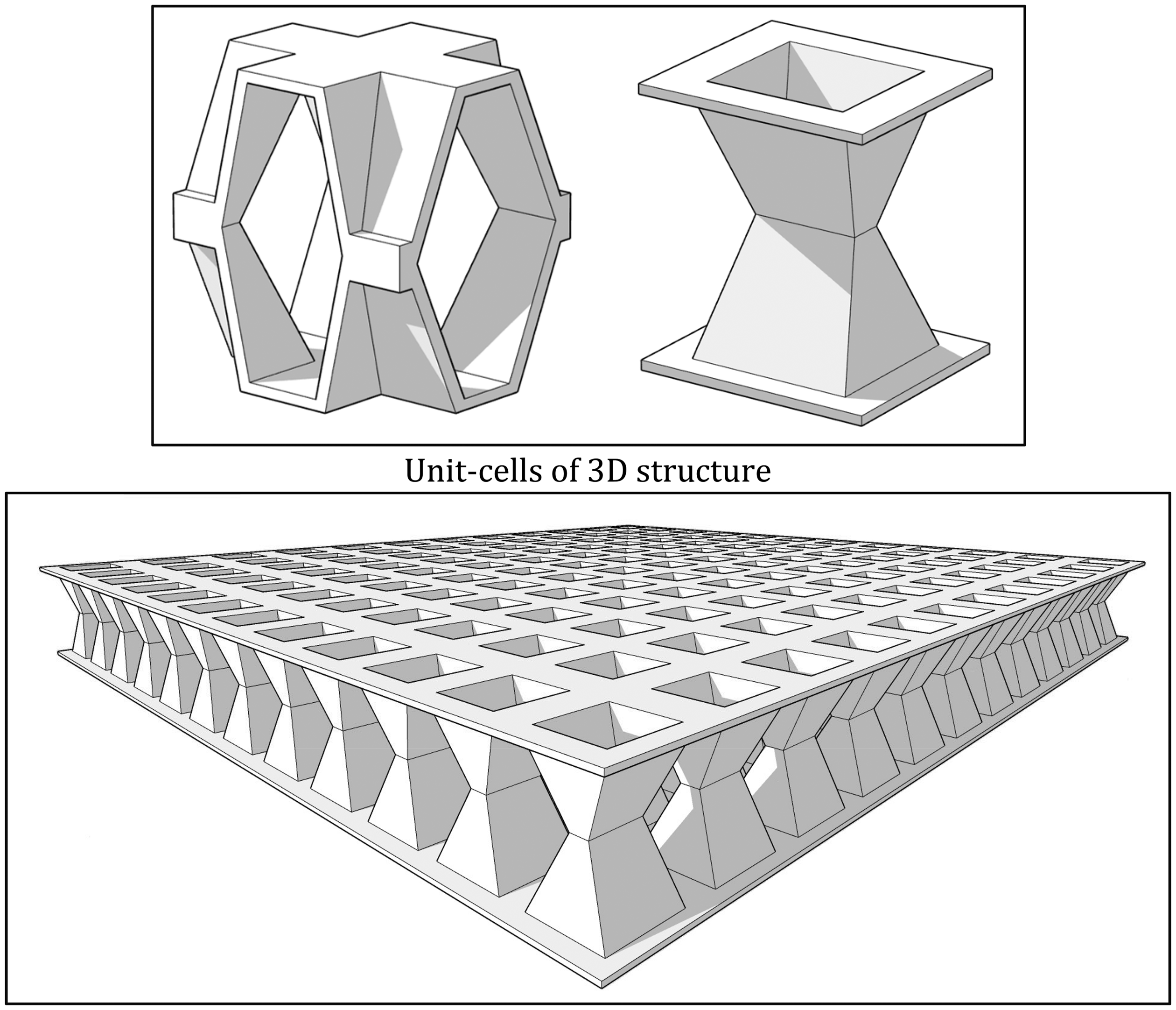
Schematic of 3D knitted structure.
These three-dimensional cellular composites are formed by the assembly of the constituent unit-cells shown in Figure 2.
The unit-cells are composed of two hollow truncated pyramids which are connected to each other. Connecting the unit-cells together creates a 3D cellular structure which can be integrally manufactured on electronic flat-knitting machines using advanced knitted techniques.
In order to produce this 3D structure (Figure 3(a)), the technique of spatial fashioning was used. This technique (also known as needle parking) is based on altering the number of operating needles from one course to another course. In order to use this technique, the flat knitting machines should be equipped with individual selection of the needles as well as holding-down sinkers. Also, a 2D plan of the 3D structure should be provided. The fabric 2D plan is an area where are positioned fashioning lines which in turn define the final 3D shape of the product. Accordingly, the 2D plan of the truncated pyramids (Figure 3(b)) was prepared.

(a) 3D plan; (b) Converting a 3D plan to 2D plan of the truncated pyramids; (c) knitting technique of 2D plan of truncated pyramids.
From the Figure 3(b), it can be observed, in certain courses only a number of needles are used for knitting process. The remaining needles do not participate in knitting process while the loops are kept on their hooks until are employed again for knitting. Once the needles become active, a fashioning line is created. The height of pyramids which are knitted according to 2D plan will be restricted because the unemployed needles are no able to remain inactive for a long time. To avoid this limitation, an alternative technique can be used as depicted in Figure 3(c). According to this illustration, courses required to form the lateral surfaces (red surfaces) of the truncated pyramid can be produced immediately after the courses required for knitting its front and rear surfaces (yellow surfaces).
Each truncated pyramid is knitted separately on one of the needle beds. Two truncated pyramids can be connected together at their upper bases (Blue surfaces in Figure 4) by two different methods. They are connected to each other either by tuck loops which are formed on both needle beds (Figure 4(a)) or by using the knit loops on one needle bed and the tuck loops on another bed (Figure 4(b)). The number of connecting courses depends on are of connection zone of the truncated pyramids. By connecting the upper bases of truncated pyramids, a unit-cell of the three-dimensional structure is created.

Knitting process for conecting the truncated pyramids to gether.
Similarly, 3D-knitted structures with different complex core geometries can be produced on flat knitting machines. But for cylindrical, cubic and prismatic core geometries, the fabric thickness will be limited similar to conventional 3D FKSF’s due to technical limitation of needle parking technique.
By altering the number of corresponding knitted courses, structural parameters such as the angle and height of the connecting layers, dimensions of the upper and lower surface layers which connect the truncated pyramids base, and geometry of structure can be adjusted. In contrast to conventional 3D-FKSFs which were already discussed, the mentioned 3D fabrics can be produced in any thickness. Also, for connecting the truncated pyramids no loop transfer process is needed. This makes the knitting process easier, faster and more reliable. To achieve a flawless and high-quality knitted structure, several adjustments on flat-knitting machines should be applied. These adjustments include choosing the appropriate loop length, the optimum amounts for yarn feeding tension, and carriage speed. Incorrect settings can lead to needle damage as well as fabric defects. Also, due to using the needle parking technique, low level of take-down speed should be applied.
In current research, two 3D knitted fabrics varying height were produced. It should be stated that other specifications of the knitted samples including angles of the connecting layers and the geometry of the connecting layers are identical. Figure 5 shows the dimensions of the unit-cell of each fabric sample. Compress-resistivity of the composites reinforced with these innovative flat-knitted fabrics was compared to a conventional multi-cell knitted spacer composite. For this aim, a single-decker type of 3D flat knitted spacer fabrics with rectangular cross-sectional shape (FKSF) was produced on the same computerized flat knitting machine. Typical knitting steps for fabricating this knitted structure has been explained elsewhere [10]. The specifications of the produced fabrics are given in Table 2.

Dimensions of the unit-cell of each fabric sample. (a) Sample VH; (a) sample VL and (c) sample FKSF.
Specifications of 3D fabrics.
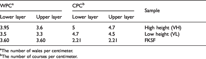
aThe number of wales per centimeter.
bThe number of courses per centimeter.
Composite manufacturing
As shown in Figure 6, the produced 3D fabric samples (VL and VH) were impregnated with epoxy resin using VARTM method. Prior to applying the vacuum by a negative pressure pump, wooden inserts were located through the fabric in order to remain unchanged during manufacture process (Figure 7). Because the wooden inserts are pulled out after composite manufacturing process, they should be covered with releasing wax, prior to insertion. The composite manufacturing was carried out via a four-stage process as follows:

Manufacturing process of 3D knitted composite.
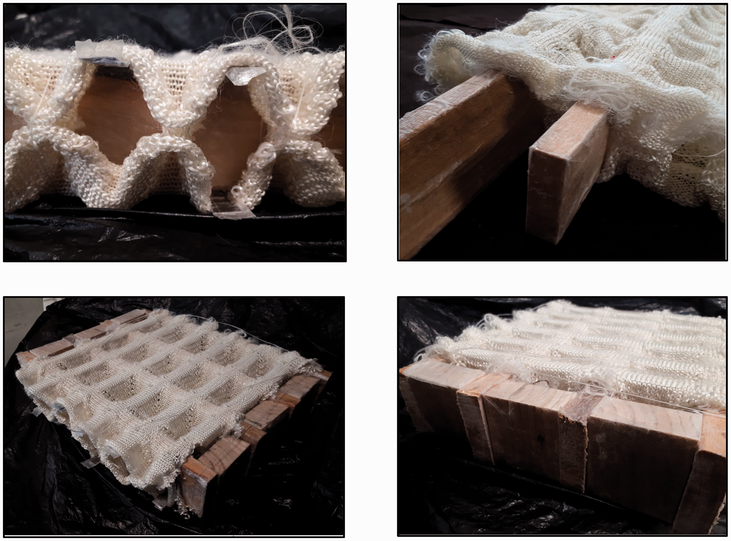
Locating the auxiliary inserts through the fabric.
Surface preparation via release agent coating with sealant tape covering;
Covering the sample with peel-ply and mesh layers;
Covering the plastic bag on the sample;
Connecting the plastic bag to resin tank and applying vacuum pressure.
The characteristics of the used resin are given in Table 3. Curing process was conducted at room temperature for 48 h. Also, composite samples were post-cured for 3 h in an oven at 80 ˚C. Figure 8 shows the produced composite samples with their dimensions. Fibers volume fraction
Properties of the used epoxy resin.


Produced composite samples.
The same manufacturing method was used for sample FKSF which has been reported elsewhere [6,10].
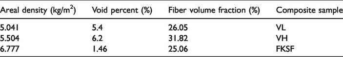
Void percentage of the composites was calculated by comparing the theoretical and experimental density [6]. Table 4 gives the fiber volume fraction, areal density and void percent of the produced composite samples.
Fiber volume fraction, areal density and void percent of the produced composite samples.
2.3 Evaluation of the flatwise compressive properties
3D composite panels were subjected to the flatwise compression loading in order to evaluate their compress-resistivity. The evaluation was carried out by Hounsfield tensile tester (model H25KS) according to ASTM C365/C365M standard method. The compression tests were performed at speed of 2 mm/min under standard conditions (temperature and relative humidity at 22°C and 50%). Figure 9 shows the compressive test. Three samples were tested for each structure and the mean values were reported.

Compression test setup.
Results and discussions
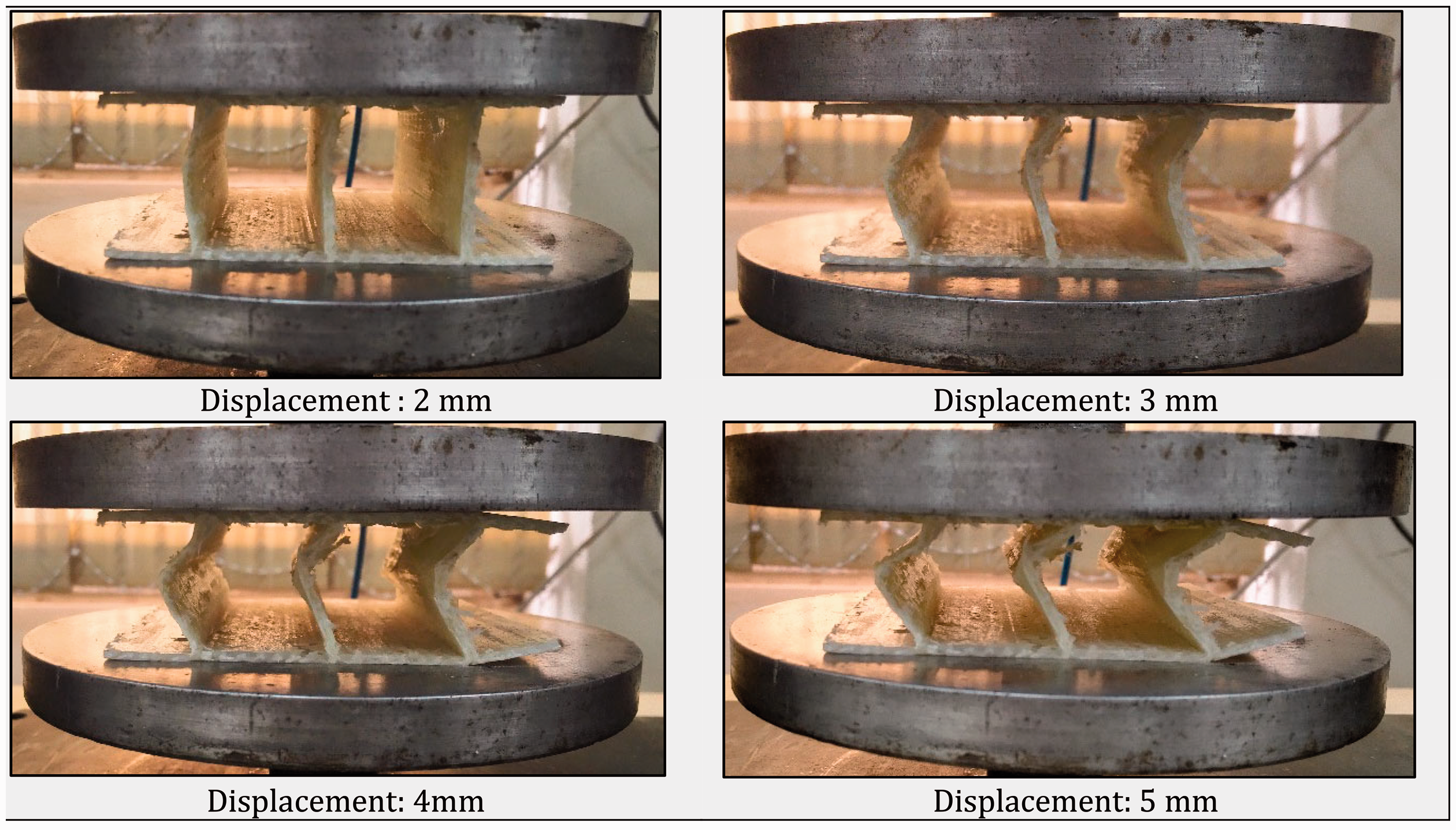
Figure 10 demonstrates the deformation stages of the composite sample (VL) during compression loading. A typical stress–strain curve obtained from the compression test is shown in Figure 11. A careful examination of the composite behavior during compression loading reveals a four-stage deformation process. In the first stage of the deformation process, the force applied to the composite’s surfaces layers which is distributed on the connecting layers increases linearly with respect to the sample displacement. In this stage, if the compressive force is removed, the 3D structure will return to its initial positions. The initial curve’s slope reflects the resistance of the specimen to buckling. If E is the elastic modulus, the Euler’s critical load (F) which is carried by the ideal column before it buckles, could be derived from the following equation [10] Deformation stages of the composite samples (VH) during compression loading. Stress–strain curve of the composite samples during compression loading: (a) elastic zone; (b) elastic–plastic zone; (c) yielding zone; (d) densification zone.


Continuing the loading process, the curve slope decreases slightly due to appear some cracks on the composite specimen which refers to start an elastic–plastic zone. The required force for specimen buckling will increase more and more until it continues to a peak point. From Figure 10, it can be concluded that buckling the truncated pyramids appears at their common surface, because the applied stresses are concentrated on this area. Once the connecting layers start to buckle, the compressive force suddenly decreases (yield zone).
Continuing the buckling process, the walls of truncated pyramids collapse after failure. When the upper and lower loading fixtures are getting closer, the deformed specimens are densified. This densification phenomenon leads to increase the applied force significantly once again (densification zone).
The features extracted from the stress–strain curves are presented in Table 5. The outcomes reveal that the curve features significantly depend on the sample structural geometry. Comparing the stress–strain curves obtained for VL and VH samples reveals the higher load-carrying capacity as well as initial slope of the former sample. This can be attributed to longer connecting columns for the VH samples in which the buckling failure happens vividly sooner and the smaller amounts of the applied stress is carried by compression force [10]. Significance differences between the results were also validated through the statistical analyzing by SPSS.17 software (sig. = 0.0). This result is in agreement with findings reported by Hassanzadeh et al. [6,10] who examined the effect of structural thickness on compressional behavior of 3D knitted glass/epoxy sandwich composites. Same as the present results, they observed that the thinner composite panels represent higher compressive stiffness and strength against applied compression loading. Also, the flatwise compression behavior of the developed composite structures is similar to behavior of conventional honey-comb sandwich structures [18].
Features extracted from the stress–strain curves of samples VL and VH.

As already mentioned, the bi-directional flat-knitted spacer composites could be replaced with conventional flat-knitted spacer composites. It will be useful to compare the compressive performance and behavior of both composites.
Figure 12 demonstrates the deformation stages of the sample FKSF, under compression loading. Accordingly, it is observed that the core buckling is a prevailing failure mechanism while the vertical connecting layers are subjected to compressive loading.
Deformation stages of the composite samples (FKSF) during compression loading.
Figure 13 represents a comparison between the stress–strain curves of the samples SKSF and VL under the flatwise compression loading. Also, Table 6 shows a comparison between the features extracted from the stress–strain curves of both samples.

Stress–strain of the composite samples (FKSF and VL) during compression loading: (a) elastic zone; (b) elastic–plastic zone; (c) yielding zone; (d) densification zone.
Features extracted from the force-displacement curves of sample SKSF and VL.

In the case of VL composite panel, the reason for lower initial slope and maximum compressive strength than the FKSF sample could be explained by the bias orientation of truncated pyramids as connecting layers relative to the applied compressive force. This result is supported by findings reported by Neje and Behera [19]. Besides, the higher thickness of load bearing walls (45 mm) also reduced the compression load-carrying capacity of these structures [10]. In spite, considering the areal density of both composite samples, it can be concluded the specific compressive strength of the sample VL will be higher than sample SKSF.
From the stress–strain curves, it can be understood that after causing the buckling failure, load-carrying capacity of the sample SKSF decreases significantly by the further loads due to lack of densification stage. This means that the both samples demonstrates quite different behavior after the failure point. Compressive stress for sample VL increases again after a temporary decrease. This leads to significant increase in absorbed energy. Also, the difference in thickness for samples VL and FKSF (from 45 mm to 26.5 mm) leads to less strain and absorbed energy for the FKSF sample.
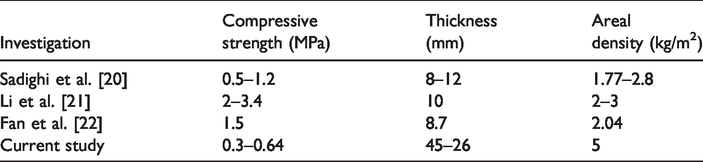
Considering the findings reported for conventional 3D sandwich panels (Table 7), it can be concluded that their compressive strengths vary at a range of 0.5–1.2 MPa with thickness variation from 8 to 12 mm [20]. In other literature, compressive strength ranging 2–3.4 MPa resulted for sandwich panels with thickness of 10 mm and the areal density ranging 2–3 kg/m2 has been reported [21]. Comparing the previously reported results with the present produced composite samples reveals that the newly designed composite panels could be desirable alternatives for conventional 3D sandwich panels to be used in technical applications. This issue becomes even more important as we know that the present sandwich panels are much thicker (45–55 mm) than previously developed sandwich panels. It means that at the same thickness, the present composites show higher compressive strength and stiffness.
A comparison between previously developed 3D sandwich panels and developed 3D knitted reinforced composite.
In order to increase the compressive performance of these structures, following methods can be used: (1) decreasing the composite thickness; (2) changing the core geometry. Both methods are possible to create a wide range of compressive strength.
Conclusions
This study introduced a novel bi-directional 3D knitted structure that has no limitation in terms of structure thickness. This structure, which is composed of two surface layers connected by two hollow truncated pyramids could be replaced with conventional multi-cell knitted spacer fabrics. Also, in comparison to conventional 3D-FKSFs, the developed structures possess easier, faster and more reliable knitting process due to removing the loop transfer process.
The results also revealed that their compression behavior is similar to the behavior of conventional honey-comb sandwich structures. Comparing the previously reported results with newly designed composites reveals that they could be desirable alternatives for conventional 3D sandwich panels to be used in terms of compressive strength. Also, the introduced 3D structures provide extra paths for fluid transmission or power cables in technical applications such as drone airfoils due to their bi-directional geometry. The 3D knitted spacer structures are not fully developed and need to be still under consideration. Flat knitting technology is able to produce diverse complex 3D structures which are competitive solution for light-weight composites. The hollow structure of the developed composites leads to lower areal density which is important for light-weight composites. These composite structures have a great potential for using in solar panels, aircraft wings, and impact-absorbers.