
Abstract
The present study investigates the improvement in high-velocity impact response of fiber metal laminates through modification of epoxy using different percentages (0, 1, 3, and 5 wt.%) of SiO2 and ZrO2 nanoparticles. To ensure a good distribution of nanoparticles into epoxy resin, the nanoparticles were dispersed by a high-speed shear mixer followed by an ultrasonic device. By using the hand lay-up technique followed by a mold pressing process, FML samples were made of 2024-T3 aluminum sheets (0.5 mm thick) and woven Kevlar fabric impregnated with modified epoxy. The high-velocity impact test on FML samples was conducted to determine the influence of epoxy modification on their specific energy absorption. The study revealed that the modification of epoxy increased the specific energy absorption up to 130% and 91% at samples with 3 wt.% of SiO2 and 5 wt.% of ZrO2, respectively. It was also observed from scanning electron microscopy analysis that incorporation of ceramic nanoparticles changed the delamination failure mechanism of matrix cracking to fiber breakage. Furthermore, finite element simulation (FES) was additionally conducted with Abaqus to predict the residual velocity and model impact response. The simulation results agree well with experimental data.
Keywords
Introduction
In recent years, the requests for materials with advanced mechanical properties have been increasing, especially in the aviation industry in which lightweight materials with high strength properties are needed.1,2 In recent decades, composite materials are frequently utilized due to their advantages such as weight saving, high strength, fatigue, and corrosion resistance. 3 Furthermore, bio-based composites are also eco-friendly and cost-saving with acceptable mechanical properties 4 ; however, all composites are weak in terms of toughness and moisture resistance. 5
Therefore, widespread modifications have been conducted among which sandwich-structured composites have emerged as an alternative since they overcame those limitations and possessed acceptable toughness. This type of composite was fabricated by covering the central section with two stiff skins.6,7 One of the most important families of this class was fiber metal laminates (FMLs). 8 These multilayer metal-fibers were made of thin laminates of metal and polymer-based composite.
Aramid reinforced aluminum laminate (ARALL) was the first class of FMLs, introduced in the 1980s. Its special characteristic was fatigue resistance 9 . In airplane design, studies indicated that ARALL was a favorite material in the lower wing and the skin of a fuselage where fatigue resistance is extremely important. Weight savings of more than 20% were easily attainable10,11; in addition to fatigue resistance and weight reduction, ARALL also represented high damage tolerance, corrosion resistance, and good flame resistance.12–15 These properties made ARALL the ideal material for the aviation industry; however, since aircraft were always exposed to high-velocity (50–1000 m/s 16 ) impacts, improving the energy absorption capacity was also required. Thus, many studies on improvement in the energy absorption capacity and toughness of ARRAL against high velocity have been started. 13
While in many investigations the influence of many parameters, including different numbers of alternating layers, different types of aluminum alloy, and different aluminum/composite thickness ratios, were analyzed, only small improvements were observed in the energy absorption.17–19
The main reason for the low energy absorption of ARALL is generally attributed to the polymer matrix. The most widely used polymer matrix, epoxy resin, suffers from major disadvantages such as low toughness, poor crack resistance, brittle nature at room temperature, and low impact resistance. Considerable efforts have been made to improve the toughness of epoxy resin, one of which was the incorporation of dispersed nanoparticles.20–22 The inclusion of a small amount of the nanofillers (e.g. 5 wt.%), because of crack deflection and the toughening mechanism of void formation, led to a significant increase in the toughness of the epoxy resin. 22 Many nanofillers including rigid nanoparticles such as TiO2, ZnO2, CaSiO3, BN, Al2O3, and SiO2 successfully enhanced epoxy toughness and tensile strength; these promising results lead to test these modified epoxy in FMLs structures including ARALL.21,23,24
Eslami-Farsani et al.25–28 conducted investigations on improving the properties of FMLs by using nanofillers. In these investigations, nanofillers with high stiffness such as graphene, graphene oxide, carbon nanotube, TiO2, and zirconia were dispersed in the polymer matrix. The results indicated many improvements in properties of FMLs, such as fracture toughness, tensile strength, electrical conductivity, wear resistance, water resistance, and flammability resistance. Kaboodvand et al. 29 studied the effect of multiwalled carbon nanotubes on the tensile strength of FMLs. The results showed that the tensile strength improved 14% by 0.3 wt.% of carbon nanotubes. Gurusideswar et al. 30 studied the effect of using nanoclay on the tensile behavior of glass/epoxy composites. The results showed that the elastic modulus and tensile strength of the epoxy/clay nanocomposites are improved by 16% and 9%, respectively.
Although in many investigations incorporation of nanoparticles improved mechanical properties of epoxy resin, the influence of using modified epoxy on the high-velocity impact response of ARALL has not yet been clarified. In the present study, ARALL panels, stiffened by using modified epoxy, are investigated to define the improvement in energy absorption capacity. SiO2 and ZrO2 nanofillers with the concentration of 1, 3, and 5 wt.% are incorporated into epoxy resin to reinforce the ARALL panel. Subsequently, high-velocity impact tests are carried out on these ARALL plates. Damaged areas are investigated to define the mechanisms that affect energy absorption capacity. Since the incorporation of SiO2 nanoparticles yields more promising results, finite element simulation (FES) technique is carried out for samples containing SiO2 nanoparticles to predict the residual velocity and model impact response.
Experimental procedure
Materials
The specifications of Kevlar-29.

The Specifications of woven Kevlar fabric.

Preparation and fabrication of samples
Nanoparticles by values of 1, 3, and 5 wt.% of each SiO2 and ZrO2 separately were added in epoxy resin. To distribute these nanoparticles, a high-speed shear mixer at the rate of 2000 r/min was used for 1 h. Then, the ultrasonic device with 24 kHz and 120 W dispersed the nanoparticles for 90 min while the epoxy was kept in an ice-water bath to stop the temperature from rising. Next, to remove the bubbles, formed in the previous step, a vacuum oven was used to degas the mixture. Finally, it was mixed with an amine hardener by the weight ratio of 100:10 followed by stirring gently to avoid the formation of bubbles for 5 min.
In order to ensure good adhesion between the aluminum sheets and the composite layer, a series of mechanical and chemical surface treatments were conducted on aluminum sheets. In the first step, mechanical treatment, after aluminum sheets were degreased with acetone, they were polished by sandpaper (No. 40). Then, the sheets were steeped in boiling water for 20 min so that OH− and H+ agents were generated on their surfaces. Finally, aluminum sheets were washed again in acetone to ensure a perfectly clean surface. To degrease sheets before performing a chemical treatment, they were pre-etched n 100 g/L NaOH solution at 60°C for 1 min.
In the second step, the chemical process, the Forest Products Laboratory (FPL) etch process, producing microscopic scratches on the sheets, was performed. Aluminum sheets were soaked in an acidic FPL etch solution, a mixture of 33 vol.% sulfuric acid and 3.3 vol.% K2CrO4 solution, at 62 °C for 30 min. Then, they were rinsed in tap water at 20°C. Finally, to dry them, sheets were kept in an oven at 40°C for 30 min.
After preparing epoxy and aluminum sheets, the hand lay-up technique was applied to fabricate the ARRAL samples. By the weight ratio of 50:50, three layers of woven Kevlar fabric were covered manually by prepared epoxy. Oriented in the same direction, three impregnated layers of woven Kevlar fabric were sandwiched between two aluminum sheets to form the stacking sequence of AL/K/K/K/AL. Finally, fabricated laminate was cured using a compression mold technique with the application of pressure (500 bar) and temperature (25°C) for 48 h. Figure 1 shows the steps of fabricating ARALL samples. The steps of fabricating ARALL samples.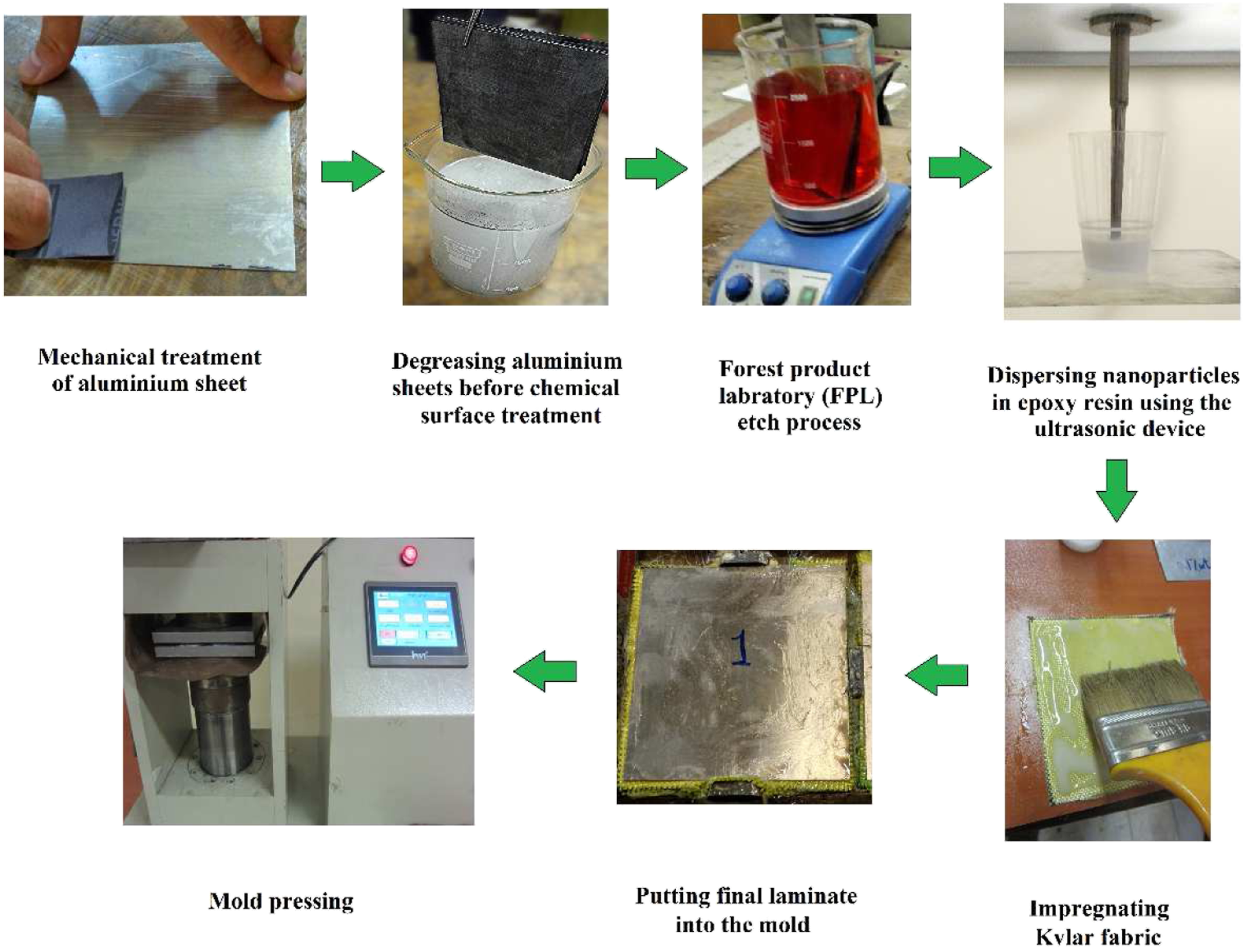
Mechanical testing and characterization
To conduct an impact test, a gas gun, as shown in Figure 2, was used to fire an aluminum cylindrical projectile with a spherical head. The outer diameter and the length were 21.5 and 40 mm, respectively. The cylinder weighed 26.85 g. The initial velocity of the projectile was 117 m/s to be assured of complete penetration. Samples were square (130 × 130 mm2). The predominant mechanism of failure on the damaged area was defined using the field emission scanning electron microscope (FESEM, model MIRA3TESCAN-XMU). A gas gun machine setup.
Experimental results and discussion
High-velocity impact results
To ensure the complete target perforation, tests were conducted at the initial velocity of 117 m/s. The residual velocity of the projectiles for each test was recorded and ballistic limit velocity (V50), the velocity at which there is a 50% probability of penetration, is calculated using equation (1)
Experimental results of high-velocity impact test on FMLs samples.
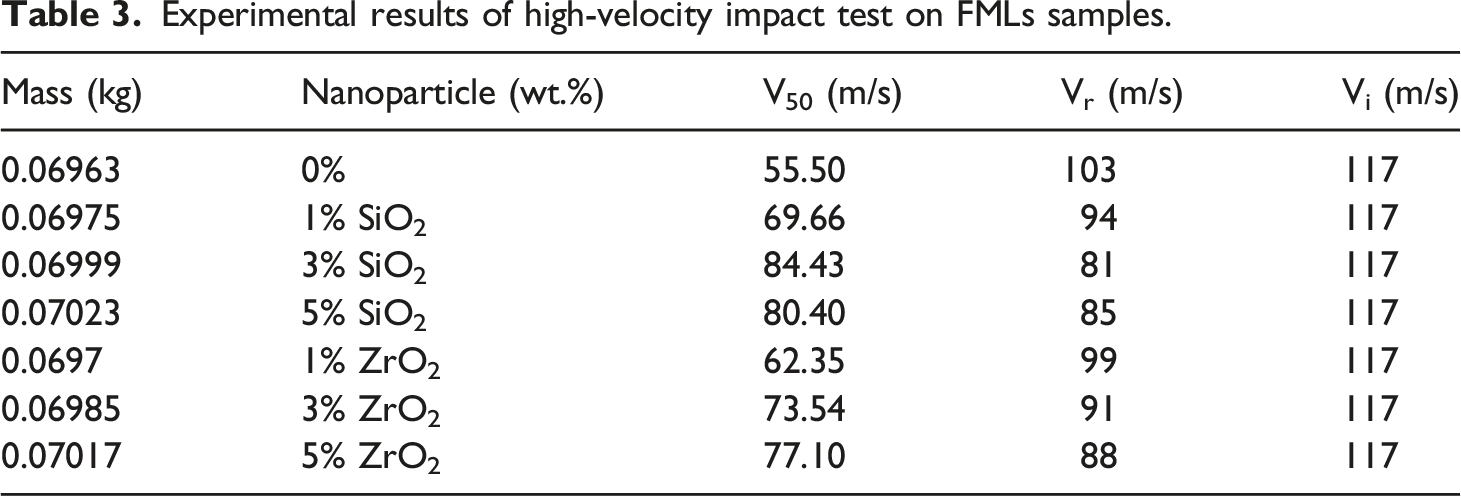
Figure 3, shows ballistic limit velocity as a function of nanoparticles content in the ARRAL samples. The samples with 3 wt.% SiO2 and 5 wt.% ZrO2 have the highest ballistic limit velocity by 84.43 and 77.10 m/s, respectively. The effect of the nanoparticles loading (wt.%) on the ballistic limit velocity of ARALL samples.
The experimental energy absorption (Eb) can be determined from ballistic limit velocity (Eb) using equation (2)
Where Mb is the mass of projectile. To exclude the influence of wight variation on energy absorption capacity, the specific energy absorption (SEA) is determined according to equation (3)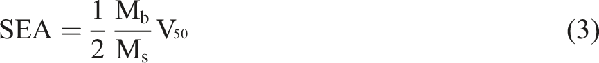
Figure 4 illustrates the variation of specific energy absorption as a function of nanoparticles loading in the ARALL samples. The effect of the nanoparticles loading on the specific energy absorption of ARALL samples.
As can be seen in Figures 3 and 4, the enhancement in limit velocity and specific energy absorption values is clearly observed with the incorporation of SiO2 and ZrO2 nanoparticles. The highest improvement of 130% and 91% in specific energy absorption was achieved by the incorporation of 3 wt.% SiO2 and 5 wt.% ZrO2 nanoparticles, respectively, compared to ARALL sample with neat epoxy. The saturation point of SiO2 nanoparticles is 3 wt.% after which the specific energy absorption decreases. This is because modified epoxy with rigid nanoparticles suffers mainly from the agglomeration, triggering a brittle response because of stress concentration and void formation. 31 The saturation level of ZrO2 nanoparticles could be 5 wt.% or more which is higher than the saturation level of SiO2. The higher saturation point of ZrO2 is attributed to its better distribution behavior. Zirconia nanoparticles show less agglomeration in general. 32
As can be seen, at the same mass concentration, higher ballistic limit velocity and specific energy absorption capacity values were achieved in the sample containing SiO2 nanoparticles in comparison to the sample containing ZrO2 nanoparticles. To explain this phenomenon, it must be mentioned that incorporating nanoparticles increases the toughness of epoxy since every nanoparticle in the epoxy matrix acts as an obstacle deflecting a crack tip. Therefore, the crack front tilts and twists when it encounters the particles and hence passes around them. 33 Both SiO2 and ZrO2 nanoparticles, used in this study, were similar in shape and size so these factors were not related to this phenomenon. However, the density of ZrO2 nanoparticle is higher than SiO2. Therefore, in the same mass concentration, numbers of ZrO2 nanoparticles are fewer than SiO2 nanoparticles, which means fewer sites to pin or deflect a crack. 34
A typical fractography
ARALL samples are made of three different layers of aluminum, epoxy, and Kevlar fabric. Since in current investigation only properties of epoxy are modified by incorporation of nanoparticles, the increase in energy absorption is mainly related to change in the failure mechanism of the epoxy layer which is defined as delamination. Delamination is a crack that runs in the resin-rich area between different plies. 35 The high-velocity impact results in localized damage which induces high transverse shear stress between all layers; This parameter in addition to the bending stiffness mismatch of aluminum and Kevlar fabric put huge stress on their resin-rich interface causing delamination.
To define the change in delamination mechanism leading to change in energy absorption capacity, samples with the lowest and the highest energy absorption, which are 0 and 3 wt.% SiO2, respectively, were selected for microscopic study (FESEM). For each sample, micrographs from the debonded face of Kevlar fabric and aluminum sheet, on the damaged area are taken. Based on observations, a schematic model of the interlaminar fracture mechanism is developed to represent the damage mechanism in the epoxy layer. Figure 5, illustrates schematically interlaminar failure and FESEM micrographs of aluminum sheet and Kevlar fabric in the sample containing neat epoxy. Interlaminar failure of the sample containing neat epoxy, (a) Schematic representation, (b) Cross section of debonded aluminum, (c) and (d) Debonded face of Kevlar fabric.
As can be seen in Figure 5a, the crack propagated predominantly through the epoxy matrix leaving on both surfaces of the aluminum and Kevlar fabrics an epoxy covering. Figure 5b shows the cross section of aluminum on the damaged area. A smooth epoxy covering on the aluminum surface suggests a brittle fracture in the epoxy layer. Figure 5c, shows the surface of Kevlar fabric; while on the center a smooth epoxy covering also demonstrates a brittle fracture in the epoxy layer, on the sides, fibers are bare, with no epoxy covering. The lack of epoxy resin on fibers, as can be seen in Figure 5d, could be related to both poor wet-out in the hand lay-up process and poor interfacial adhesion between aramid fibers and neat epoxy resin
36
due to mismatch of thermal expansion coefficient in the curing process.
37
Therefore, in the sample containing neat epoxy, the main mechanism of interlaminar failure is the matrix cracking which is the result of the low strength and brittle nature of neat epoxy. However, in the sample containing 3 wt.% SiO2, large number of fractured fibers are observed on the delaminated Kevlar fabric, as can be seen in Figure 6. Fractured fibers on the surface of delaminated Kevlar fabric in sample containing 3 wt.% SiO2.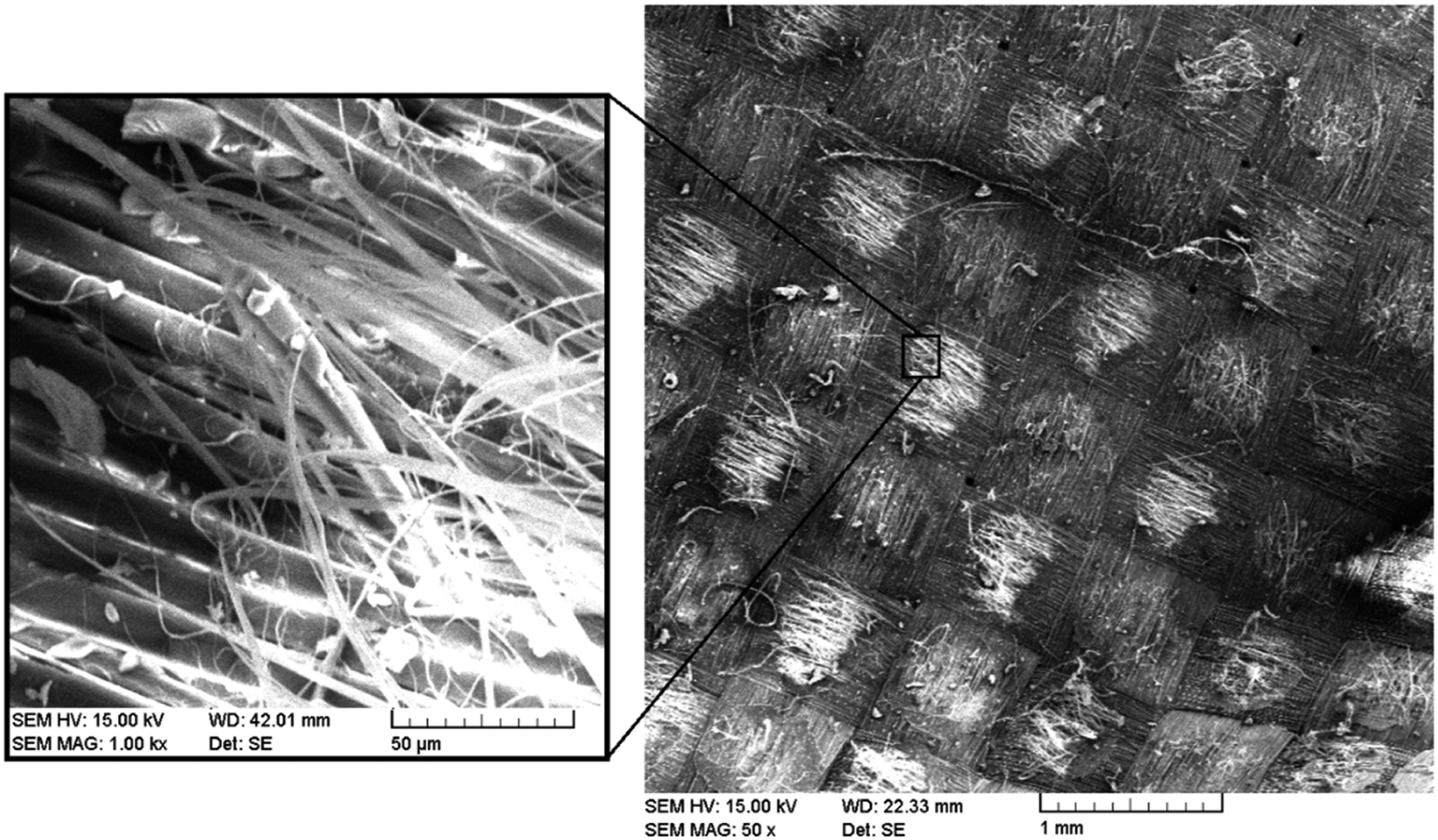
Figure 7 illustrates schematically interlaminar failure and FESEM micrograph of aluminum sheet and Kevlar fabric in the sample containing 3 wt.% SiO2. Interlaminar failure of the sample containing 3 wt.% SiO2, (a) Schematic representation, (b) Cross section of debonded aluminum, (c) Debonded face of Kevlar fabric.
As can be seen in Figure 7a, in some areas the crack propagated through the Kevlar fabrics and cut fibers. This leaves an epoxy layer, including some broken fibers, on the aluminum surface as can be seen in Figure 7b. The torn-out fibers on the Kevlar fabric surface can be seen clearly in Figure 7c.
It must be mentioned that a crack propagates through the weakest regions. In the sample containing neat epoxy, the brittle matrix of epoxy is the weakest part; therefore, the crack can propagate easily in the epoxy matrix, leaving a smooth layer of epoxy resin on the surface of aluminum and Kevlar fabric. However, the incorporation of nanoparticles in epoxy enhanced the strength of the epoxy matrix, making the crack shift its path into Kevlar fabrics. Breaking the fibers makes an increase in the level of energy consumption during crack propagation.
Finite element simulation
In this section, the FES technique is applied to simulate the response of the composite structure to the high-velocity impact experiment. FES model is established for the aluminum, Kevlar fabric, epoxy layer, and impactor in Abaqus/CAE 2020. All geometries, boundary conditions, and material properties are taken into consideration as near as experimental setup. Analyses are performed in a dynamic explicit framework.
Simulation condition and setup
Geometrical modeling
The FE model was assembled of the ARALL sheet and impactor. The hemispherical impactor was modeled as a rigid body with a mass of 26.58 g. An illustration of the FE model of the impactor is shown in Figure 8. The FE model of the impactor, designed from the projectile in the experimental test.
The experimental dimension of the ARALL plate was 130 × 130 mm2. However, since an area of 1.5 mm wide all around the plate was fixed with a high-pressure loading in the experiment, it was modeled with the size of 100×100 mm2. The ARALL plate with 1.24 mm thickness was composed of two layers of aluminum, three layers of Kevlar fabric, and four layers of epoxy resin. As in experimental analyses, a Ply thickness of 500 μm was assigned to the aluminum layer. Also, since the weight ratio of Kevlar to epoxy is 50:50 and their density is almost the same, their thickness ratio was considered 50:50. Therefore, the thickness of 120 μm were assigned to four layers of epoxy, 30 μm for each layer; similarly, the thickness of 120 μm were assigned to three layers of Kevlar fabric, 40 μm for each layer.
Boundary conditions
To simulate the real condition, the six freedoms of the edges of the ARRAL plate except for the epoxy layers, which were modeled as the cohesive film, were fixed to limit all displacement and rotation. Also, the initial velocity of 117 m/s is given to the projectile in the negative Z-direction.
To calculate common interactions and simulate the contact behavior, a general contact algorithm, using the penalty and “hard” contact methods, was applied in Abaqus/Explicit. Also, defining a true friction coefficient was of great importance since it can change the transferred forces in contact surfaces. The friction coefficient for general contact was set at 0.2.
38
Figure 9 shows the model and boundary condition of the ARALL specimen. The model and boundary condition of ARALL specimen.
Material model
Mechanical properties of aluminum 2024-T3. 39


Johnson-Cook parameters of aluminum 2024-T3. 39


Johnson-Cook fracture constants of aluminum 2024-T3. 39

As was mention before, one of the main reasons for high energy absorption in FMLs was delamination. In this simulation, delamination was considered as the failure of the adhesive bond. Also, the adhesive bond simulation was based on the method (CZM) using uncoupled traction. Details are described in the Abaqus manual. 40
Properties of epoxy with different SiO2 nanoparticles loading (wt.%). 26

Properties of woven Kevlar fabric. 42

Damage criteria of the Hashin 3D model. 43

Damage initiation properties of woven Kevlar fibers. 42


Discretization
The number and types of elements allocated for each part.

Model validation and discussion
Simulation results of high-velocity impact test on ARALL samples with different SiO2 nanoparticles loading (wt.%).


Residual velocity as a function of SiO2 loading.
As can be seen, the numerical results are in good agreement with experiment results. However, there are differences in some results especially in samples with 5 wt.% SiO2 nanoparticles. These differences can be related to the difference in materials, procedures of mixing, and curing conditions, which yield different amounts of nanoparticle agglomeration. Figure 11 shows the numerical prediction of stress distribution in each component of ARALL samples after complete perforation. The numerical prediction of stress distribution in each component of ARALL samples.
As can be seen, the most damaged parts are the epoxy layers placed between aluminum and Kevlar fabric. The reason is the bending stiffness mismatch between aluminum and Kevlar fabric which induces huge stress to their epoxy-rich interface. Also, the total damage in epoxy layers decreases as the nanoparticles’ loading increases in epoxy resin. This is because of an increase in the toughness of epoxy. However, in sample containing 5 wt.% SiO2, because of agglomeration of nanoparticles, the toughness of epoxy decreases and so the total damage in the epoxy layers increases again.
Conclusions and further research
Conclusions
In this study, the influence of incorporation of ceramic nanoparticles (SiO2 and ZrO2) into epoxy resin on the high-velocity response of Kevlar fibers-epoxy/aluminum laminate composites was investigated. The high-velocity impact response of each sample was used to determine specific energy absorption and ballistic limit velocity. A typical fractography of samples was conducted to determine the interlaminar failure mechanism which affects energy absorption capacity. Five FESs of the high-velocity impact test on samples containing SiO2 nanoparticles were also applied to predict the residual velocity and model the impact response. The results of the investigation were as follows: 1. In all samples containing modified epoxy, the specific energy absorption and ballistic limit velocity were higher than the sample containing neat epoxy. 2. The reason for an increase in energy absorption of ARALL samples is the change in the interlaminar failure mechanism from matrix cracking to fibers breakage. 3. The specific energy absorption and ballistic limit velocity of samples containing SiO2 nanoparticles increased more than ZrO2 nanoparticles. It attributes to a lower density of SiO2. 4. The highest growth rates in specific energy absorption were at 3 wt.% SiO2 and 5 wt.% ZrO2 by 130% and 91%, respectively. 5. The FES results, including residual velocity, were in good agreement with the experimental analysis, verifying the simulation model.
Suggestions for future research
1. Limitations in the incorporation of nanoparticles within an epoxy matrix could be overcome by using the sol-gel process in the epoxy resin. 2. Surface modification of nanoparticles could also be applied to enhance specific energy absorption of ARALL to a higher extent. 3. Impact modeling of Kevlar fabric using the actual geometry of yarns would yield more promising results.
Footnotes
Declaration of conflicting interests
The author(s) declared no potential conflicts of interest with respect to the research, authorship, and/or publication of this article.
Funding
The author(s) received no financial support for the research, authorship, and/or publication of this article.