
Abstract
The transfer process of heat and water vapor in a porous fiber membrane was investigated through the simulation of a 3D model for optimizing the configuration design. 3D models with different fiber orientations and porosity were constructed by the parameter input method, and the accuracy of the model was validated by the coefficient of determination (R2) between the apparent velocity of the model and the air permeability of the membrane. The permeability of 3D model was used to reflect the discrepancy in fiber orientation of the model. The influences of fiber orientation and porosity on heat and water vapor transfer were surveyed by the coupled physics of heat transfer and dilute substance transfer. Since there was no temperature difference in the entire domain, heat conduction (10−9 W/m2) and moisture convection (10−14 mol·m−2·s−1) were faint in the model. With the diffusion of water vapor in the moisture, the heat convection flux and water vapor diffusion flux gradually decreased and reached equilibrium. When the permeability was increased by adjusting the fiber orientation (from 1.002 to 1.200 m2), the heat convection flux and water vapor diffusion flux followed a similar growth pattern due to the coupling effect of heat transfer and water vapor transfer. The R2 for the heat convection flux and water vapor transmission rate of the simulations and experiments with different porosity (44.87, 47.64 and 50.15%) were 0.999 and 0.923, respectively, which demonstrated the validation of the simulation in heat and water vapor transfer.
Keywords
Introduction
The heat and water vapor transmission properties of the fabric are important factors for its wearing comfort.1,2 The heat transfer performance adjusts the heat dissipation efficiency of human body, thereby maintaining the body temperature balance. 3 The transmission characteristics of water vapor adjust the transmission rate of sweat on the skin surface and improve the evaporation and heat dissipation of sweat. 4 The thermal comfort of the fabric is usually characterized by experimental tests of water vapor resistance (R et ) and water vapor permeability (W d ),5,6 which reflects the heat convection and water vapor transmission. However, the R et and W d could not reveal the process of heat and water vapor transfer because the transfer of heat and water vapor is coupled and time-dependent.7,8 Besides, polyurethane (PU) porous fiber membrane prepared by electrospinning is usually applied in thermally comfortable and breathable fabric due to the low R et and high water vapor transmission rate (WVT).2,5 Nevertheless, porous fiber membrane possesses complex microstructures due to the discrepancy in fiber orientation and the porosity. 9 In general, the permeability (κ) of a porous medium is a geometric parameter of the porous structure, 10 which is resolved by the apparent velocity. 11
In recent years, the 3D model is commonly used to investigate the influence of structural features on the permeability.12,13 The 3D model of the porous fiber membrane can be constructed by imaging technology (X-ray micro-tomography, CT), numerical definition (triply periodic minimal surface, TPMS), or computer graphics software (Digimat).14–16 With the development of computer technology and numerical algorithm, the finite element method (FEM) is utilized to resolve the velocity field of porous media through computational fluid dynamics (CFD) simulation,17,18 which is beneficial to construct an accurate 3D model of the membrane. Furthermore, the simulation of the 3D model is increasingly applied in the research of the heat and mass transfer process19,20 because the experimental method is inconvenient to make a series of samples, and it is hard to precisely control the fiber orientation to discuss the influence of structure parameters.21,22 Although some research has surveyed the heat transfer of thermal protection fabric through the 3D model,23,24 few studies were utilized to analyze the coupled transfer of heat and water vapor to improve the thermal comfort of fabrics because the transfer process involves heat convection, heat conduction, water vapor diffusion, and moisture convection.25–27 Therefore, it is significant to give a deeper slight into the process and mechanism of heat and water vapor transfer in 3D models with different porous structures (including fiber orientation and porosity).
In the study, a 3D model with porous fiber structure was constructed by inputting structural parameters in Digimat software. The porous structure of the model was evaluated by the apparent velocity resolved in the creeping flow physic. The transfer of heat and water vapor in the 3D model was simulated by COMSOL software. The heat transfer and water vapor transfer were coupled by the physics of heat transfer and dilute substance transfer. The simulation displayed the transient transfer process of heat and water vapor in the 3D model. Meanwhile, the simulation exhibited transfer fields of heat and water vapor at different locations. The heat convection, heat conduction, water vapor diffusion, and moisture convection were calculated to characterize the thermal comfort of the porous fiber membrane. The influences of fiber orientation and porosity on the heat and water vapor transfer were investigated to optimize configuration design and improve the thermal comfort of the membrane.
Experimental section
Electrospun polyurethane (PU, Elastollan 1190A10) porous fiber membrane was prepared based on the previously described method
28
(Figure 1). The typical parameters of the PU porous fiber membrane included a thickness of 40 ± 5 μm, average fiber diameters (according to the statistics of Image-Pro Plus software) and porosity (calculated by the density method,
29
Supplementary equation (S1)). The porosity of the electrospun membrane is significantly affected by the fiber diameter,
30
and the fiber diameter is mainly controlled by the spinning solution concentration during the electrospinning process.
31
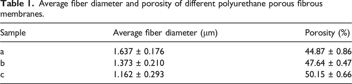
The appropriate concentration of PU spinning solution is 16∼20 wt% (Supplementary Figure S1). In order to clearly distinguish the fiber diameter and porosity, only three samples (the spinning solution concentration of the prepared samples was 16, 18, and 20 wt%) were selected to verify the correctness of the simulation, as shown in Table 1. An air permeability tester (FX 3300, Japan) evaluated the air permeability (defined as the volume of air flowing through a unit area of the sample per unit time under a specified pressure difference, m/s) of the sample at the pressure drop of 100 Pa, according to the GB/T 5453 standard. The water vapor resistance (R
et
, m
2
·Pa·W−1) and water vapor permeability (W
d
, g·m−2·h−1·Pa−1) of the sample were measured by the water vapor resistance testing instrument (YG 606G, China, Supplementary Figure S2), referring to the GB/T 11048 standard. The sample was tested at the constant temperature of 308.15 K and relative humidity (RH) of 60%.The surface temperature (T
surf
) of the test board was 308.15 K (assuming it was the surface temperature of human skin). According to the GB/T 11048 standard, R
et
is defined as the ratio of the vapor pressure difference between the two sides of the sample to the evaporation heat flow per unit area passing through the sample vertically, which is expressed as follows FE-SEM image of the PU porous fiber membrane with a porosity of 47.64% and a diameter of 1.373 μm: (a) front view and (b) cross-sectional view. Average fiber diameter and porosity of different polyurethane porous fibrous membranes.

According to the GB/T 11048 standard, W
d
is defined as the mass of water vapor passing vertically through a unit area of the sample in a unit of water vapor pressure difference per unit time and calculated by the formula
Here,
Methodology
3D model of porous fiber membrane
To investigate the heat and water vapor transfer through the porous fiber membrane, the 3D model (including fiber diameter, fiber orientation, and fiber volume fraction) was generated by Digimat software. In the model, the construction of the membrane was based on the assumption that the fibers in the membrane had a simple shape (for example, a long cylinder).
32
The orientation of the fibers was two-dimensional (2D) random,
33
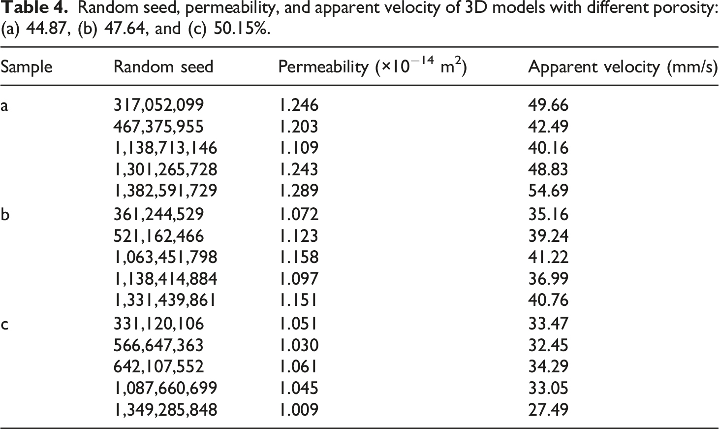
and the orientation was generated by the random seed in Digimat software. The random seed is a kind of initial random number that generates a series of random numbers via constant iteration in the software. Thereby, the fiber orientations in the membrane could be controlled by the sequences of the random numbers. Moreover, it is necessary to generate different random seeds for the models with different porosity, and it is reasonable for the deviation of different random seeds to generate different arrangements of the fibers in the membranes with different porosity. Furthermore, it was supposed that the fibers in the membrane were completely interpenetrated.
12
Figure 2 shows an example of a 3D model with a fiber volume fraction of 52.36% (the porosity was 47.64%), a fiber diameter of 1.373 μm, and a thickness of 40 μm. An example of a 3D model with a porosity of 47.64% and a diameter of 1.373 μm: (a) perspective view and (b) side view.
The discrepancy in the microscopic structure of porous medium is usually reflected by the permeability (κ, m2),
9
which is a geometric parameter of the porous structure and a measure of the resistance of the structure to the fluid flowing through the medium.
10
The permeability is resolved by the apparent velocity (u, m/s),
11
referring to the Darcy’s law
12

Here,
In the study, the apparent velocity (i.e., volumetric flow rate per unit cross-sectional area)
34
was resolved through the creeping flow physic in COMSOL software, at the inlet boundary condition of 100 Pa and the outlet boundary condition of 0 Pa, according to air permeability test conditions of the membrane.18,35 Furthermore, the side surfaces and internal interfaces (the outer surfaces of the fibers) were non-slip walls because the flow is mainly in the through-plane direction and lateral flows are negligible.
33
Dry air flowed into the simulation domain through the inlet and left from the outlet, and the boundary conditions of creeping flow were shown in Figure 3. Referring to the air permeability of the membrane (from 0.0226 to 0.0459 m/s), it can be found that the Mach number (defined as the ratio of the flow velocity to the speed of sound, where the speed of sound is 346 m/s) is very low. Therefore, the change in density of dry air caused by pressure is negligible, and it assumes that the creeping flow is incompressible.
36
The density of the dry air is constant and does not change with time, so the creeping flow is steady. The flow behavior is controlled by the mass conservation and the momentum conservation equations, as shown below
37
Demonstration of the boundary conditions for solving the apparent velocity.


Here,
Simulation of heat and water vapor transfer
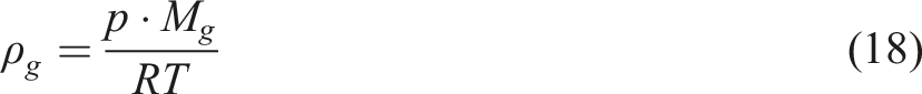
Owing to the connection of gaseous phase density (referring to the equations (10) and (17)) in the physics of heat transfer and dilute substance transfer, heat transfer and water vapor transfer are coupled together in the transfer process. Furthermore, the water vapor concentration (c
v
, mol/m3) changes with time (equation (13)), resulting in the density of the moisture in the heat transfer to change over time (equations (18) and (19)). Therefore, heat transfer and water vapor transfer in the porous fiber membrane are time-dependent.
8
In order to furnish a greater insight into the process, the following assumptions are adopted in the study: (1) The solid phase (PU) is treated as homogeneous and isotropic, and the deformation of the membrane is so small that it can be ignored.
38
(2) The gaseous phase is an ideal mixture of water vapor and air.
39
(3) The driving force of gravity is ignored because the depth of moisture transmission is very shallow.
19
Heat transfer
In the model, the influence of heat radiation could be neglected at low temperature,
22
thus, the heat transfer of the solid phase (PU) is mainly heat conduction,
40
and the heat transfer equation is shown as follows

Here, ρ
s
is the density of the solid phase (kg/m3), C
s
is the heat capacity of the solid phase (J·kg−1·K−1), and T is the temperature (K). t is the time (s),
The heat transfer of the gaseous phase not only has heat conduction but also includes heat convection,
41
and the heat transfer equation is as follows

Here, ρ
g
is the density of the gaseous phase (kg/m3), C
g
is the heat capacity of the gaseous phase (J·kg−1·K−1),
The heat convection of the gaseous phase is generated by the flow of air and water vapor
42
; thus, the 
Here, 

Water vapor transfer
During the heat transfer process of the gaseous phase, the transfer of the gaseous phase involves the diffusion of water vapor in the air and moisture convection, the convection–diffusion equation in the transient regime for the gaseous phase is expressed as follows
44

When water vapor (as a solute) diffuses in the air (as a solvent), according to the equations (14) and (15), even for saturated water vapor (c
vsat
: 2.194 mol/m,
3
at 308.15 K), the molar coefficient of water vapor (X
v
) is only 0.055, while the molar coefficient of air (X
a
) is as high as 0.945, indicating that the content of water vapor in the air is extremely low, and the gaseous phase is a dilute substance.

Therefore, diffusive transport of water vapor in the air is described by Fick’s law, and the water vapor diffusion flux 

Here, M
a
is the molecular weight of air (kg/mol), M
g
is the molecular weight of the gaseous phase (kg/mol), and ρ
g
is expressed as follows
47

Mesh parameters and boundary conditions
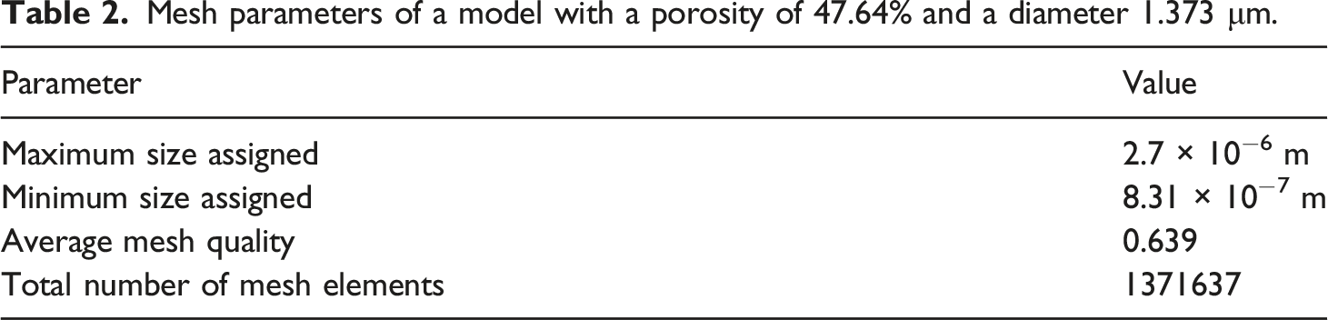
To achieve a good prediction accuracy and reduced computational time, tetrahedral elements were assigned to the whole domains, including the solid domain (PU fibers) and gaseous domain, as shown in Figure 4, and the mesh parameters of the model were given in Table 2. The boundary conditions of heat and water vapor transfer were displayed in Figure 5. During the heat transfer process (Figure 5(a)), one side of the model was a temperature boundary (308.15 K), the other side was an open boundary with a constant temperature of 308.15 K. The side surfaces and internal interfaces (outer surfaces of the fibers) were thermal insulation. Water vapor did not undergo a phase transition (such as condensation) at the internal interfaces because the ambient temperature was the same as the water temperature. During the process of water vapor transfer (Figure 5(b)), saturated water vapor concentration (2.194 mol/m3) was assigned to one side, and ambient water vapor concentration was allocated to the other side. There was no flux on the side surfaces and internal interfaces because these surfaces were non-slip walls.
33
Furthermore, the initial values of the entire domain were a constant temperature of 308.15 K and the ambient water vapor concentration. Meshing scheme of the (a) whole domains and (b) solid domain. Mesh parameters of a model with a porosity of 47.64% and a diameter 1.373 μm. Demonstration of the boundary conditions for solving (a) the transfer of heat and (b) water vapor.

Numerical solution and validation

Results and discussion
Construction of 3D model
The permeability of porous fiber membrane is a function of the fiber orientation and porosity of the membrane.
10
In the 3D model, fiber orientation was generated by Digimat software based on a random algorithm, and the porosity could be allocated by inputting the fiber volume fraction in the software. In order to investigate the permeability of the 3D model, the steady-state velocity field Velocity field of dry air in the 3D model resolved by the creeping flow physic. (a) x–z section velocity and (b) y-z section velocity in the 3D model. Random seed, permeability, and apparent velocity of 3D models with different porosity: (a) 44.87, (b) 47.64, and (c) 50.15%. Apparent velocity of the 3D models and air permeability of PU porous fiber membranes with different porosity.


Heat transfer process
The heat transfer of the 3D model was simulated by COMSOL software when the water vapor was transmitted in the porous domain.
48
As shown in Figure 9(a), the heat conduction fluxes (equation (9)) of the 3D models with the porosity of 47.64% and different fiber orientations (reflected by the permeability) were all extremely small (10−9 W/m2) because there was no temperature difference in the entire domain; besides, the heat conduction fluxes decreased slowly with the time. According to the equations (10)–(12), the heat convection flux ( Variations in the (a) heat conduction flux and (b) heat convection flux as a function of time in the 3D models with the porosity of 47.64% and different permeability.

The heat convection fluxes of the models dropped gradually and then maintained a balance (Figure 9(b)). The heat convection field of the 3D model at 1000 μs was exhibited in Figure 10, which displayed the flow of heat convection from the external environment to the porous domain and exhibited the difference of heat convection flux at different locations in the domain. Heat convection flux field in the 3D model at 1000 μs.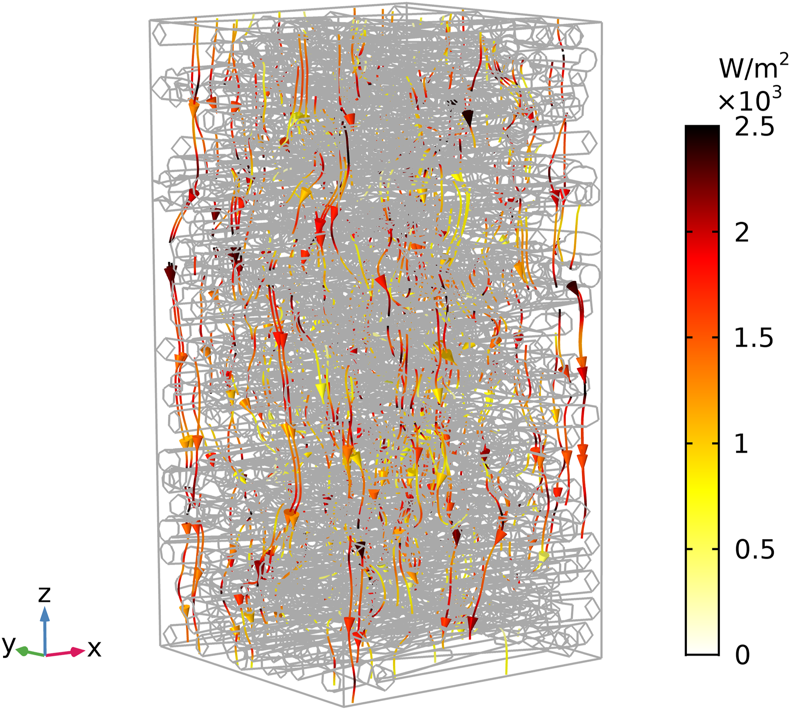
Water vapor transfer process
The moisture convection flux and water vapor diffusion flux were calculated in the simulation to investigate the water vapor transfer of the 3D model. According to the equations (13) and (15), the moisture convection flux (
Figure 11(a) shows that the moisture convection fluxes of 3D models were extremely low (10−14 mol·m−2·s−1) and declined in a small range over time, indicating that the moisture convection in the 3D models were faint when the ambient temperature was the same as the water temperature. Furthermore, the water vapor diffusion flux (equation (14)) of 3D models decreased with the passage of time and reached an equilibrium (Figure 11(b)). Simultaneously, the water vapor diffusion flux of the 3D model at different locations in the porous domain is shown in Figure 12, which also illustrated the flow of water vapor from the evaporation side to the external environment. Variations in the (a) moisture convection flux and (b) water vapor diffusion flux as a function of time in the 3D models with the porosity of 47.64% and different permeability. Water vapor diffusion field in the 3D model at 1000 μs.

Influence of porous structure on transfer
When the ambient temperature was the same as the water temperature, heat conduction and moisture convection were faint. Therefore, the transfer of heat and water vapor mainly involved heat convection and water vapor diffusion in the 3D model. The effect of fiber orientation (reflected by permeability) on the transfer of heat and water vapor was investigated as shown in Figure 13. In the 3D model with the porosity of 47.64%, as the permeability increased from 1.002 to 1.200 m2, the heat convection flux increased from 1236.6 to 1298.8 W/m2, and the water vapor diffusion flux increased from 0.382 to 0.402 mol/(m2 s). It demonstrated that the improvement of permeability by adjusting the fiber orientation facilitated the heat convection and water vapor transmission. And Figure 13 also shows that the increase in heat convection and water vapor diffusion followed a similar pattern. Heat convection flux and water vapor diffusion flux in the 3D models with the porosity of 47.64% and different permeability.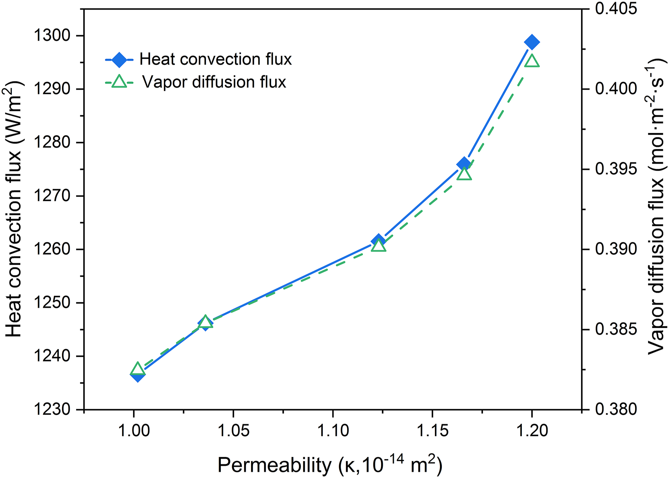
The accuracy of the simulation in heat transfer was surveyed by the contrast between the simulation results and experimental data. According to the equation (1), the heat convection flux in the experiment is expressed as
Figure 14(a) displayed that the R2 for the heat convection fluxes of the simulations and experiments with different porosity was 0.999, which demonstrated the validity of simulation results. Meanwhile, the heat convection flux increased from 1207.74 to 1282.44 W/m2 with the increase of the porosity from 44.87 to 50.15%. To validate the correctness of water vapor transfer in the 3D model, the water vapor transmission rate (WVT, mol·m−2·s−1) in the simulation was compared with that converted by the W
d
(equation (2)). The WVT of the 3D model in the simulation can be expressed as
51
(a) Heat convection flux and (b) WVT of the 3D models and experiments with different porosity.

The WVT in the experiment is defined as the mass of water vapor that vertically passed through a unit area of the sample per unit time, which can be calculated by the formula
Figure 14(b) displayed the agreement between the simulations and experimental data. The R2 for the WVT of the simulations and experiments with different porosity was 0.923, which proved the validity of simulation for the water vapor transmission. Similarly, the WVT increased from 0.0273 to 0.0290 mol/(m2 s) with the increase of the porosity. It meant that the increase in porosity had the same promotion effect on the heat convection and water vapor transmission.
Conclusions
In the work, heat and water vapor transfer of porous fiber membrane was investigated through the simulation of the 3D model to characterize the thermal comfort of the membrane. The apparent velocity of the model was resolved by the creeping flow physic and compared with the air permeability of the membrane to verify the accuracy of the 3D model. The coupled transient transfer of heat and water vapor in the porous fiber membrane was analyzed by the coupled physics of heat transfer and dilute substance transfer, and heat convection flux and WVT were used to validate the correctness of the simulation.
The permeability was used to reflect the discrepancy in the porous structure of 3D models with different fiber orientations and the same porosity. As the permeability was increased by adjusting the fiber orientation, the apparent velocity also increased. Furthermore, the apparent velocity decreased with the increase of porosity due to the decline of permeability. The R2 for the apparent velocity of the simulations and experiments with different porosity was 0.988, which proved the accuracy of the 3D model. The model verified by the apparent velocity was applied to survey the influences of fiber orientation and porosity on the transfer of heat and water vapor. With the diffusion of water vapor in the 3D model, heat convection and water vapor diffusion gradually abated and reached a balance over time. However, heat conduction (10−9 W/m2) and moisture convection (10−14 mol·m−2·s−1) were faint, owing to the lack of temperature difference in the entire domain. As the permeability increased from 1.002 to 1.200 m2, the heat convection flux increased from 1236.6 to 1298.8 W/m2, and the water vapor diffusion flux increased from 0.382 to 0.402 mol/(m2 s), which meant that increasing the permeability by adjusting the fiber orientation was conducive to the transfer of heat and water vapor. As the porosity increased from 44.87 to 50.15%, the heat convection flux increased from 1207.74 to 1282.44 W/m2, and the WVT increased from 0.0273 to 0.0290 mol/(m2 s), indicating that the increase in porosity had the same promotion effect on the heat convection and water vapor transmission. The R2 for the heat convection flux and WVT of the simulations and experiments with different porosity were 0.999 and 0.923, respectively, which demonstrated the validation of the simulation for heat and water vapor transfer.
Supplemental Material
sj-pdf-1-jit-10.1177_15280837211041772 – Supplemental Material for Simulation of coupled transient heat and water vapor transfer in porous fiber membrane with different fiber orientations and porosity
Supplemental Material, sj-pdf-1-jit-10.1177_15280837211041772 for Simulation of coupled transient heat and water vapor transfer in porous fiber membrane with different fiber orientations and porosity by Haihong Gu, Li Gao, Guoqing Li, Ni Li and Jie Xiong in Journal of Industrial Textiles
Footnotes
Declaration of conflicting interests
The author(s) declared no potential conflicts of interest with respect to the research, authorship, and/or publication of this article.
Funding
The author(s) disclosed receipt of the following financial support for the research, authorship, and/or publication of this article: This work was supported by the National Natural Science Foundation of China (10902099) and the Natural Science Foundation of Zhejiang Province, China (LY16E030007).
Supplementary Material
Supplementalry material for this article is available online.
Appendix
References
Supplementary Material
Please find the following supplemental material available below.
For Open Access articles published under a Creative Commons License, all supplemental material carries the same license as the article it is associated with.
For non-Open Access articles published, all supplemental material carries a non-exclusive license, and permission requests for re-use of supplemental material or any part of supplemental material shall be sent directly to the copyright owner as specified in the copyright notice associated with the article.