
Abstract
The rapid proliferation of electronic devices and their operation at high frequencies has raised the contamination of artificial electromagnetic radiations in the atmosphere to an unprecedented level that is responsible for catastrophe for ecology and electronic devices. Therefore, the lightweight and flexible electromagnetic interference (EMI) shielding materials are of vital importance for controlling the pollution generated by such high-frequency EM radiations for protecting ecology and human health as well as the other nearby devices. In this regard, polymeric textile-based shielding composites have been proved to be the best due to their unique properties such as lightweight, excellent flexibility, low density, ease of processability and ease of handling. Moreover, such composites cover range of applications from everyday use to high-tech applications. Various polymeric textiles such as fibers, yarn, woven, nonwoven, knitted, as well as their hybrid composites have been extensively manipulated physically and/or chemically to act as shielding against such harmful radiations. This review encompasses from basic concept of EMI shielding for beginner to the latest research in polymeric-based textile materials synthesis for experts, covering detailed mechanisms with schematic illustration. The review also covers the gap of materials synthesis and their application on polymeric textiles which could be used for EMI shielding applications. Furthermore, recent research regarding rendering EMI shielding properties at various stages of polymeric textile development is provided for readers with critical analysis. Lastly, the applications along with environmental compliance have also been presented for better understanding.
Introduction
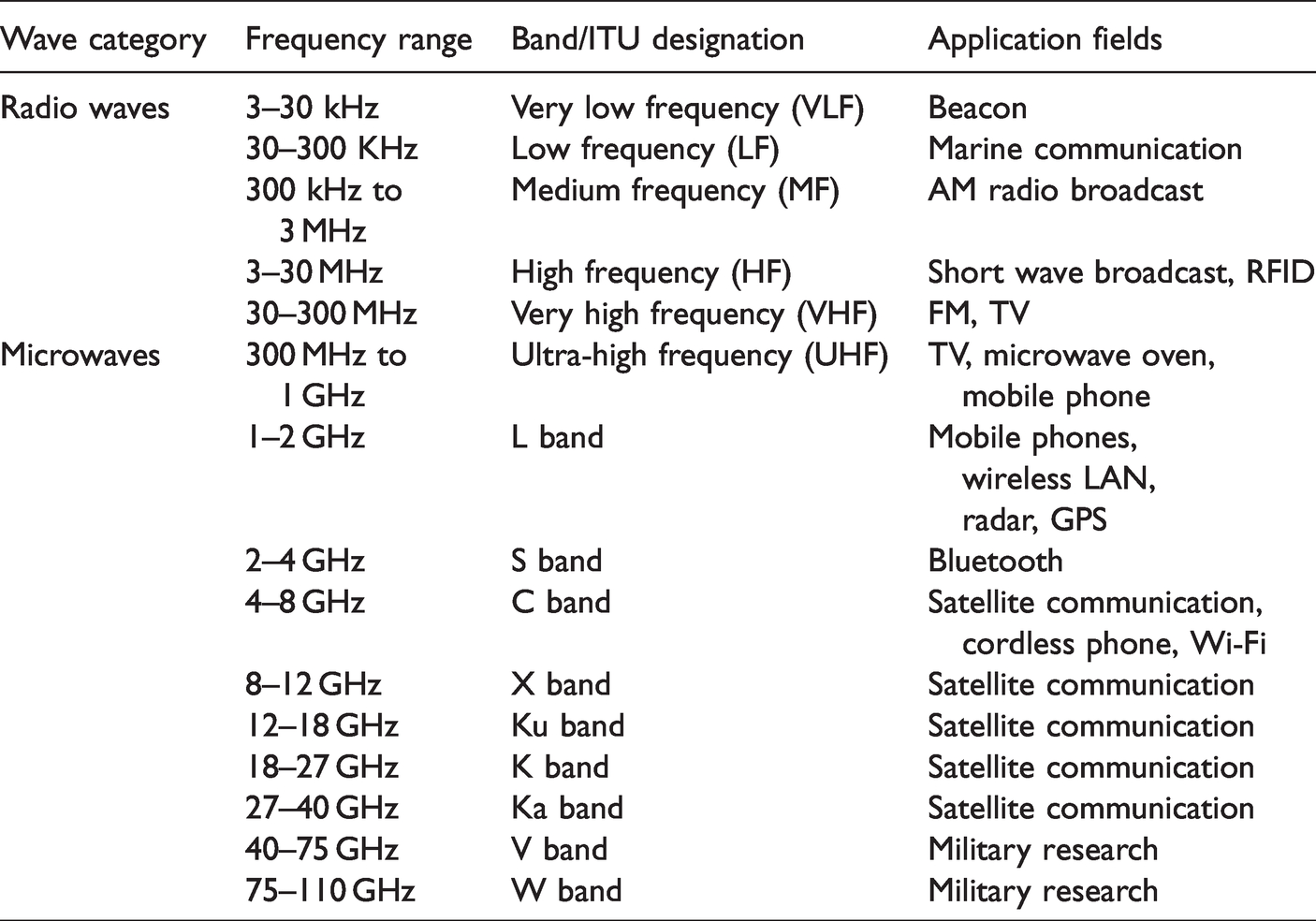
Due to the rapid proliferation of electronic devices, we are living in such an atmosphere that is overcrowded by electromagnetic (EM) radiation. Each device driven by electric current acts as a source of these radiations such as mobile phones, radio, television, microwave oven, satellite stations, radio communication base stations and devices for distributing electric energy such as transformers and electric power lines. Exposure of the general public to these radiations depends on the state of industrialization of a given area. The exposure of residents of large cities is higher in comparison with small cities and rural areas. EM radiations spectrum covers a complete range of waves: from radio waves on one side to X-rays and gamma rays on the other side of the spectrum in Figure 1. Applications of these radiations in different communication areas are presented in Table 1.

Electromagnetic spectrum, sources and applications.
Radio and microwaves in communications [1].
These are responsible for catastrophe everywhere by creating chaos among different communication channels and harmful effects for living beings, also known as electromagnetic interference (EMI). The most commonly RF range (104 to 1012 Hz) of the EM spectrum is involved in EMI. Conduction and radiation are two modes of electromagnetic interference [2]. In human beings, they are causing diseases such as depressions, leukemia, cancer, etc. and affect DNA due disturbance of electrical impulses [3,4]. These high-frequency radiations have been classified as group 2B carcinogen by the World Health Organization (WHO) [5]. It has proven that children are more vulnerable to harmful effects of such radiations than adults because the absorption of these radiations is more in rapidly growing/developing cells [6]. According to the study reported by the American National Institute of Environmental Health Sciences, clear shreds of evidence of cancerous tumors in the hearts of male rats were found after their high exposure to radiofrequency radiations used in mobile phones [7]. Data stealing and malfunctioning of electronic devices are among the other examples of the destructive effects of this EMI. Thus, chaos and interference between different EM radiations has become the prime challenge of the current era, thus shielding is the only solution for curbing such inferable consequences. Protection of delicate regions including electronic devices and human beings from radiating and/or conducting EM radiations is known as EMI shielding.
There exist regulatory bodies for safe use of radiofrequency/microwave radiations such as International Electrotechnical Commission (IEC), Federal Communications Commission (FCC), Restriction of the Use of Certain Hazardous Substances in Electrical and Electronic Equipment (RoHS) and Waste Electrical and Electronic Equipment (WEEE). Traditionally electroconductive materials (metals such as copper, steel, aluminum etc.) were employed for shielding based on Faraday’s cage principle. These metallic shielding suffer from certain limitations such as heavyweight, lower flexibility, rendering higher formability cost and corrosion/oxidation. Therefore, burgeoning research is mainly focused on the development of shielding materials. Vital requirements for such materials are predominantly conductivity and loss of dielectric or magnetic permeability.
To exploit the full potential of these materials, they are loaded onto different structures such as nanocomposite, foam, layered structures, etc., for instance, polymeric textile-based composite structures. Owing to lightweight, flexible, cost-effective and easily conformable structures, textiles are the most preferred structure for EM shielding purposes. Moreover, the porous structure of textile surfaces is advantageous in terms of providing sites at internal interfaces for multiple reflections of EM radiations. This allows substantial consumption of EM energy [8]. Smart textiles have wider applications ranging from wearable garments to automotive textiles, from protective to aerospace textiles. In addition to providing shielding against harmful effects of electromagnetic radiations, textile surfaces are also preferred for preparing spatial filters also called frequency selective surfaces that make use of conductive material incorporated on a dielectric substrate. Such intermittent surfaces transmit a portion of the frequency bands and mirror some other frequency bands [9].
A plethora of work has been done for shielding materials starting from metals to conductive fabrics and composite structures. Due to an increase in demand for lightweight and flexible shielding materials with ease of application and stable shielding performance at elevated temperature, textile-based structures are preferred as they owe required properties. Moreover, wearable functional devices and materials are highly in demand and textile surfaces are considered to best suited to fulfill all requirements of wearability including breathability, comfort, sustainable and non-hazardous. Skeleton and surface morphology of textiles can be easily modified chemically and physically to develop hierarchal structures of materials capable of interacting with EM radiations [10]. According to the Committee for Conformity Assessment on Accreditation and Certification of Functional and Technical Textiles, some of the grades and performance specifications of EMI shielding textiles in general and professional use are presented in Table 2 [11].
Operational particularization of textile based electromagnetic shielding materials [11].

In this review, we discuss the recent progress on textile-based shielding materials including rendering EMI shielding behavior, at manufacturing stages of textiles, and to the as-prepared textile surfaces that are originally transparent to these radiations. Moreover, obtained values of EMSE (Electromagnetic shielding effectiveness), shortcomings, challenges, and prospects of textile-based EMI shielding composites are put forward, that will be helpful to researchers and technologists working in this vast and challenging field.
Measurement techniques
The electromagnetic shielding effectiveness (EMSE) can be measured by several methods described by standards of the Institute of Electrical and Electronics Engineers (IEEE) Std. 299, the American Society for Testing and Materials (ASTM) D4935, ASTM E1851, the Turkish Standards (TS) EN 50147-1, 2005, the Military (MIL) Standards 285 (withdrawn). The principle of EMSE measurement is mostly performed in two steps. Shielding efficiency is enumerated from transmission between two antennas with the setting of an open door and close door of the enclosure. The shielding efficiency (SE) is a difference between these two values, in decibel (dB) unit. Due to the establishment of diverse standards for EMSE assessment, it has been difficult to directly compare SE of a shield evaluated by different test standards.
EMI shielding mechanism
EMI control is normally achieved by reducing EMI emissions from the source, modifying, or diverting the propagation path of the electromagnetic energy, and improving the immunity of the susceptor. Impinging of EM waves on a surface is followed by the phenomenon of reflection, absorption, and transmission. Attenuation of these waves occurs by reflection, multiple reflection and absorption as can be seen in Figure 2, depending upon materials characteristics and nature of waves. Moreover, multiple reflections also play a role in the attenuation of EM radiations.

Shielding mechanism, a pictorial representation/Interaction of EM waves with a solid layer.
Shielding efficiency (SE) could be defined as a parameter that measures how well a material impedes the EM energy of a certain frequency when passing through it. According to Schelkunoff’s theory, the total EMSE is determined by reflection (SER), absorption (SEA), and multiple reflections (SEM). Multiple reflections can be ignored when the SE reaches 15 dB, thus SE is determined by reflection and absorption [12].
SET = SER + SEA + SEM
SET = SER + SEA (When SET
The reflection loss decreases with increasing frequency, whereas the absorption loss increases with increasing frequency.
Reflection shielding (SER)
Such type of shielding occurs from materials possessing electrical conductivity property (moving charge carriers). Generally, materials having higher conductivity such as metal owing to their highly reflective properties are widely employed to isolate an object from EM rays. The basic principle of such type of shielding is Faraday cage, in which space inside the cage is impervious to external electric fields. In the case of limited conductive materials, EM waves penetrate through them. When rays reach the opposite face of the material, they get reflected from the boundary of the shield. Reflection loss (SER) is related to the relative impedance mismatching between the surface of the shielding material and the EM waves. It depends on ray’s frequency, material’s conductivity and magnetic permeability [13] according to equation (1)
Absorption shielding (SEA)
Absorption shielding is related to permeable materials i.e. magnetic materials. The absorption loss is a function of the product σ · µ. The shield should possess electric and/or magnetic dipoles that can interact with electric (E) and magnetic (H) vectors of incident EM radiation. The amplitude of the incident waves is reduced exponentially when it passes through such materials. Absorption occurs due to induced current and polarization relaxations of the shielding materials [15]. The absorbed energy of EM waves is converted into thermal energy that results in increased temperature of the material [16]. The generalized form for absorption loss is given in equation (2) [17]
Carbon materials are dielectric loss materials, which consume the electromagnetic energy by conductivity and polarization relaxations with the advantages of being lightweight, high conductivity and aspect ratio, good resistance against corrosion and excellent mechanical properties [15].
Multiple reflection shielding (SEM)
Another mechanism for EM waves attenuation is the phenomenon of multiple reflections that involves reflection at various surfaces or interfaces in the shield i.e. waves come back to the first boundary due to reflection from the second boundary and fall on the second boundary after reflection from the first boundary. This process of reflection and re-reflection continues as shown in Figure 2. This mechanism of multiple internal reflections is followed when multiple surfaces or interfaces are present with a large specific surface like porous or hierarchal geometries and composite with fillers [18]. Generalized equation of multiple reflections is given in equation (3) [17]
These multiple reflections can be ignored in two cases, when the material’s thickness is larger than skin depth or when the value of SEA > 10 dB. In such cases amplitude of waves is left negligible till reaching the secondary boundary, thus SEM can be ignored.
Internal reflections are especially common for composites filled with small dimensions fillers, e.g. nanoparticles. They might be polymer composites filled with electrically conductive fillers such as particles/ nanoparticles of metals, carbon or carbon fibers. The loss due to multiple reflections can be neglected when the distance between the reflecting faces or interfaces is large compared to the skin depth. Their shielding effectiveness is higher when filler concentration is greater and for higher aspect ratio parameter of filler (ratio of fiber length to thickness/diameter) [19].
Perspective of skin depth
In the case of electrical conductors, the EM radiations possessing high frequency penetrated only near the surface region of the material. This is called a skin effect. The exponential decrease in the electric field component of the waves is observed with an increase in depth of the conductor. With an increase in depth of the conductor, an exponential reduction of the electric field component of the waves takes place. The depth at which drop of filed is 1/e of its incident value is termed as skin depth (δ). Here, e is the Euler’s number and 1/e = 0.37) [20]. This is the distance that reduces the wave to at least 37% of its original amplitude17. The skin depth is given in equation (4)
The Simon formula can be employed to estimate shielding effectiveness in the case of composite structures made of electroconductive components [21]. It is given in equation (5)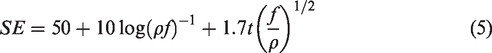
EMI shielding performance
Shielding structures, in ideal cases, must possess impedance matching (between free space and shielding material) as prompted by permeability and permittivity, thus making them vital parameters for the design of effective shielding [22]. The best option to minimize the impedance mismatch is either increase the effective permeability or decrease the effective permittivity. In non-magnetic materials shielding is mainly governed by reflection, while in magnetic conducting metals shielding is dominated by absorption rather than reflection. Such materials are used to develop EMI shielding structural designs by loading them to a suitable material (composite structures), and for the resulting heterogeneous microstructures, relative complex permittivity and relative complex permeability become very important parameters for determining the performance of the shield [23]. Relative complex permittivity is given in equation (6)
Relative complex permeability is given in equation (7)
The dielectric loss depends on conductivity and polarization loss. A positive relationship exists between conductivity and dielectric loss. On the other hand, polarization loss depends on material selected and its fabrication processes; and is based on electronic, ionic, dipole orientation and interfacial polarization. Ionic and electronic polarization occurs at very high frequency (above 103 GHz), therefore their effect can be excluded at lower frequency regions. Dipole polarization is due to residual defects and groups on the material [24]. The interfacial polarization and concomitant relaxation play a role in an assorted system by the presence of space charges entrapped at the interface [25]. In the case of complex relative permeability, μ′ and μ″ are associated with the energy density and magnetic loss power stored in the magnetic system. Therefore, it can be assumed that in case of complex microstructures possessing heterogeneity, these parameters hold an intricate dependency on the size, geometry, conductivity and volume fraction of all the constituents [23].
Magnetic loss comes from natural resonance, exchange resonance and eddy current loss in the microwave frequency band [26]. The natural-resonance equation correlates the natural resonance frequency (fr) to an anisotropy filed (Ha) as given in equation (8)


Z0 = impedance of free space. Hence maximum absorption will take place when the difference between impedance of free space and the shielding material is possibly minimum 23. In the case of air, the value of the impedance (Z0) is 377 Ω, hence the ideal condition for impedance matching is Zin = Z0 = 377Ω [23]. Moreover, an ideal EM absorption should make the effective width as broad as possible, which can be controlled by the quarter wavelength equation (12)
The percolation threshold of conductive material is given in equation (13) [29]
In terms of metallic filaments; diameter, arrangement, quantity, and type of metal are among the important factors affecting shielding performance. The detail has been discussed in the Hybrid conductive yarns section.
EMI shielding materials
Term radar absorbing materials (RAMs) is used scientifically for the class of materials possessing the ability to interact with electromagnetic waves and attenuating them by reflection, absorption and multiple reflection/scattering [30]. Such materials have found increasing applications in electronic communications, stealth technology and more recently in textile clothing. A material must possess high electrical conductivity and magnetic permeability to interact with EM radiations. Literature has indicated that one material is unable to fulfill all requirements for preparation of EMI shielding structure; therefore, ingenious combinations of materials are used to ameliorate the EMI shielding. By this time, a profusion of research work has been published to explore the ideal shielding material. Studies in the last decade revealed that semiconductors, dielectric ceramics, metal particles/foams, magnetic oxides/ferrites/particles, intrinsically conducting polymers, electrically conductive carbon black/nanotubes/fibers and other carbon derivatives such as graphene, have been widely explored. These materials need to load on a substrate directly either by coating on textiles surfaces or in the form of filler to make a shield. Different types of materials give different shielding performance depending upon the method of loading/application. While designing a shielding material, the percolation threshold should be observed at a low loading level of the filling materials. Such fillers tend to aggregate resulting in deteriorating the performance of the article, it is, therefore, necessary to make a good dispersion of these materials [31]. The physical structural pattern of the final absorber consisting of filler has a significant effect on the yield [32].
Pictorial presentation of the percolation threshold is shown in Figure 3. In the case of conductive nanomaterials, 0D materials (metallic nanoparticles), their intrinsic aspect ratio is so small that high loading is inevitable to make a conductive path in the matrix. On the other hand, 1D (metallic nanowires, carbon nanotubes), and 2D (graphene, boron nitride) fillers owing high aspect ratio, are required in lesser to make the conductive path in the matrix. It can be assumed that elaborately shaped particles are more likely to be connected to their nearest neighbors to form a continuous conductive path and the least elaborated shape is the spherical shape which requires up to 40% stuffing to develop the percolation threshold. On the other hand, irregularly shaped particles such as carbon black are considered moderately structured particles. These types of particles require around a 33% loading level to reach the percolation threshold [33–35]. Incorporation of such materials to a substrate, for instance, textiles, gives protection from detrimental effects of EM radiations. Different materials employed for EMI shielding are mentioned in Figure 4.

Pictorial presentation of the percolation threshold.

Materials having intrinsic EMI shielding characteristics.
Metals
Metals in the form of sheet/foil were employed earlier for providing shielding against EMI radiations but due to heavyweight and high costs, their use was eliminated later. Metallic filaments were made part of the textile skeleton that was also replaced by nanoscale metallic materials due to processing difficulties. Metals such as iron, nickel, cobalt, silver, aluminum, platinum, magnesium [36] and gold have been widely employed to combat these harmful radiations. These metals are used in the form of filaments, flakes, powders, and wires. Alloys of these metals are also employed to get benefits from properties of each component, such as mumetal containing 15% Fe, 2% Mo, 5% Cu, 77% Ni as main ingredients.
Metals possess higher electrical and thermal conductivities. Due to high conductivity (presence of free electrons), metallic materials attenuate EM rays by reflection, however, the limitation in their application is due to heavyweight, corrosion susceptibility, high processing cost, poor wear and scratch resistance. Work of Lie et al indicated that bare AgNWs oxidized only in 90 days [37]. Moreover, their nanoparticles should be used in high concentrations (about 40% by weight) for EMI shielding purposes [38].
Carbonaceous materials
These materials have widely been employed for preparing EMI shielding structures capable to intercept EM waves and attenuate them by absorption along with augmentation in mechanical properties of the substrate. Moreover, these materials have low density, good electrical conductivity, and chemical stability. Such dielectric loss materials include carbon black, graphite, CNTs (Carbon nanotubes), graphite nanosheets, graphene, graphene oxide, reduced graphene oxide, carbon fibers, etc. Electrical, mechanical, magnetic, and optical attributes of the articles fabricated from these superb materials can be tailored according to the requirement, for instance, EMI shielding. These materials utilize EM energy by conductivity and interfacial polarization, residual surface defects and possess advantageous traits such as lightweight, high conductivity, excellent mechanical properties, high aspect ratio, high permittivity, environmental and thermal stability [15]. Moreover, carbonaceous materials are regarded as sustainable EMI shielding materials as they can be obtained by carbonizing the biomass which comes under the category of renewable resources [39].
Unfortunately, the carbonaceous materials have limitations such as processing reliability, manufacturing feasibility and mechanical flexibility sometimes required in certain applications [40]. Moreover, for such dielectric absorbers to act as an effective shield, heavy thicknesses are required [41].
Synthetic metals
Intrinsically conducting polymers (ICPs) also known as synthetic metals, are among the most attractive candidate for EMI shielding. Commonly used ICPs are presented in Figure 5. As compared to metals, these synthetic metals possess characteristics like low density, noncorrosive, gentle processing conditions, tunable conductivity, and flexibility. However, these intrinsic conducting polymers suffer from poor mechanical strength [38]. These ICPs include polypyrrole, polyphenylene vinylene, PEDOT: PSS (Poly(3,4-theylenedioxythiophene) polystyrene sulfonate), polyaniline, polythiophene etc. These polymers find their use in sensing applications, preparation of shield against harmful EM radiations, and making a protective layer on metal surfaces.

Commonly employed ICPs.
These macromolecules possess conjugated double bond, and sp2 hybridization makes them conductive which is the prerequisite for the preparation of conductive EMI shield. These dielectric loss materials attenuate EM radiations mainly by absorption, thus these are considered as one of the most attractive materials for the preparation of structures capable of curbing harmful EM rays. These conductive polymers owe moving charges and dipoles in their molecular structure. Both attributes are responsible for the reflection and absorption of EM radiations. The EMI shielding capability of these conducting polymers by reflection and absorption mechanism arises from the moving charges (polarons and bipolarons) and bound charges (dipoles) available at their backbone [42].
Ceramic materials
Ceramic materials are evolving as a significant class of materials for protection against harmful EM radiations to be employed at high-temperature applications. Examples of ceramic fibers are SiC fibers [43], carbon fibers [44], glass fibers [45], and Al2O3 fibers [46]. Usually, their fibrous structures are used as a reinforcing component in ceramic-based composite structures [45]. Ceramic based nanomaterials include SiC nanowires (SiCNWs), nanotubes, whiskers, and nanobelts made of SiC. These ceramic based EMI shielding materials attenuate EM waves by absorption dominating mechanism. To achieve higher shielding performance i.e. reflection loss less than 20 dB, absorption bandwidth higher than 4 GHz and coating thickness less than 2 mm, etc. [43], hybridization of these materials is done with oxides of metals, magnetic metals or carbonaceous materials [46]. However, metal-based additives are prone to corrosion and magnetic loss property is lost at a temperature higher than their curie temperature.
Complex permittivity plays a role in the absorption of EM waves. With an increase in frequency, a gradual decrease in permittivity and hence polarization of the material takes place due to change in electric field component of incident radiations. This dipole field opposes the applied field and is responsible for the attenuation of EM waves [43].
Being lightweight, thermally and chemically stable and environmentally durable (means no effect of environmental conditions like heat, moisture etc.), these ceramic-based high strength fibers can be employed to construct EMI shielding material such as textile-based materials for instance by weaving them into fabrics [47–49], in the form of electrospun components [43], as reinforcing component in making composite structures [46].
Oxides
Owing to fascinating magnetic properties, oxides of Ti, Fe, Mn, Ni, Cu, Mg, Li, Zn and Si have been employed for a long time in various application fields such as electronics. These oxides can be used to prepare EMI shielding materials. Among these, ferrite is a class of materials that comprise of mixed metal oxides having iron oxide as an essential component. These oxides and barium titanate (BaTiO3) can absorb incident EM waves for attenuation. Apart from oxides of iron that possess high magnetic permeability, other oxides such as SiO2, BaTiO3, etc. also possess high dielectric constant. Such materials provide electric/magnetic dipoles at high frequencies that interact with EM radiations for attenuation by absorption mechanism [50–53] These materials are employed as fillers in polymeric coatings [54] or during fiber spinning [55].
MXene
MXene, the member of 2D nanomaterials family, is the combination of transition metal carbide/nitrides and is becoming popular among researchers (can be called ideal material) due to their excellent intrinsic electrical conductivity, Joule heating performance, layered structure and polar surface chemistry that is tuneable [56]. MXene can be represented by general formula Mn+1XnTx, where M represents the transition metals such as Ti, Zr, Nb, Mo, V while X represents C and/or N and T represents the end group such as –OH, =O, and –F [57]. This superb 2D nanomaterial can be engineered into films [58], aerogels [59], fibers [60] etc. Their surface polar groups (OH, O, and/or F groups) give them hydrophilic character and enable them to interact with the polymers bearing polar moiety without scarifying the electrical conductivity of MXene.
Hybrid materials
Currently, available shielding materials require higher loading and thickness to be able to give acceptable shielding performance. These are also limited to narrow bandwidth and poor impedance mismatch. Therefore, in the field of materials chemistry, the researchers are trying to develop high-performance hybrid materials to combat wider bandwidth EM radiations at low loading levels by absorption dominating mechanism (reflection loss less than −10 dB) [61]. From the literature review, it can be concluded that researchers are focusing on two types of characteristics may be called intrinsic and extrinsic EM properties. The intrinsic properties comprising of the reduction of mismatch by taking electrical conductivity, complex permeability and permittivity into consideration. The extrinsic properties include frequency range, thickness, morphology and construction of material.
The coalescence entente of late contrast from the single to hybrid nanoscale materials depicting to assemble every vital property in a solitary amalgamated for better shielding efficiency. Some dielectric and magnetic materials are selected to develop nanocomposites with 2D and 1D nanomaterials. Such materials may find their application in wearable electronics, communication industry, artificial intelligence, and EMI shielding, etc. Examples of such materials are the porous three-dimensional flower-like structure of Co/CoO [62], Nitrogen-doped porous carbon nanoplates embedded with CoS2 [63], flower-shaped nickel/carbon microsphere [63], hollow Fe3O4-Fe nanoparticles coupled with graphene [64] etc.
EMI shielding textiles
Textile fabrics are suitable for myriad applications ranging from daily clothing to aerospace, protective to automotive, for instance, EM radiations protective textiles. The military industry is considered as the origin of EM wave blocking textiles developments and later on, the civilian industry felt the need for the development of such protective textiles [65]. Traditionally electronic conductive materials have been made part of textile fabrics to impart electrical conductivity to the fabrics as a prerequisite for EM radiations shield, as textile polymeric materials are nonconductive.
Initially, more attention was paid to convert textile surfaces physically and/or chemically into EMI shield and improving its performance by integrating metallic components into textile skeletons. Later, other functionalities such as durability, wearability, comfort, and breathability were also made part of the research in developing EMI shielded textiles. These shielding materials combat EM radiations by reflection. Due to rapid innovations in the communication and electronics industry, the concentration of these artificial radiations was increased to a hazardous level becoming ecological and harmful pollution. Shielding by reflection does not eliminate this pollution but protects humans and devices and in some cases such as in military and electronics applications, this mechanism is not preferred. Therefore, researchers are trying to develop such materials that combat these radiations by absorption while maintaining intrinsic properties of textile surfaces though the importance of reflective textile surfaces cannot be neglected completely in certain cases such as absorptive surfaces can be used in transformers, motors, generators, etc. [66]. Skeletons made of all sort of fibers including natural (cotton, bamboo, etc.), regenerated (lyocell), synthetic (polyester, nylon, etc.) and high-performance fibers (carbon, Kevlar, etc.) have been modified physically and chemically to develop textiles capable of protecting against destructive EM waves [67–71].
The next section will give a brief overview of preparation techniques/methods for developing such textile structures and shielding performances of resulted skeletons. An effort has been made to gather some techniques/methods for developing hierarchal structures, decoration/loading of shielding materials onto textile surfaces based shielding materials that will help the reader in the selection of a technique/combination of techniques according to the requirement. However, the evaluation and comparison of such materials with data analysis is quite difficult due to many uncontrolled factors such as thickness, EMI shielding measuring frequency for performance, the type of polymer matrix, processing and fabrication techniques.
Rendering EMI shielding property at spinning stage
Textile structures are developed from synthetic and/or natural fibers. Synthetic fibers are poor conductors of electricity due to hydrophobicity and accumulate static charges produced by rubbing [72,73]. On the other hand, natural fibers are hydrophilic and have relatively higher electric conductivity in favor of static charge dissipation but not for effective EM shielding [74]. For antistatic applications, the typical resistivity recommended is 102–106 Ω.cm. For EMI shielding, materials having a surface resistivity below 10 Ω.cm are considered suitable as a shield for electromagnetic interference (EMI). The effectiveness of shield is largely a function of surface conductivity [75].
For EM waves having frequency >300 MHz, higher electrical conductivity is required for equal attenuation of both electric and magnetic components. But in case of lower frequency radiations (<30 MHz) shielding from the magnetic component is very difficult and possible with ferromagnetic materials. However, shielding from the electric component is satisfactory for some applications [76]. For attenuation of waves, conductive metal fibers/filaments are used solely or mixed with natural/synthetic fibers (both conventional and elite fibers like carbon, Kevlar etc.) [68,69], nonconductive fibers are coated with conductive materials including metals and intrinsically conducting polymers. These yarns are used to make fabrics suitable for EM shielding purposes. Blending with high-performance fibers gives higher strength to the shield as compared to conventional fibers. Pure metallic yarns and other conductive yarns have also been used to make stitches/any pattern to woven, knitted, composite fabric [77,78].
The diameter of metallic fibers affects the shielding performance of the fabric. Metal fibers having smaller diameters are preferred due to the phenomenon of skin depth. As more portion of its skin volume would be involved in attenuation of radiations. The higher the frequency of the EM wave, the smaller the penetration depth into the fiber. The electrical field of a plane wave drops exponentially with increasing depth into the conductor [79].
The shielding performance of metalized fabrics depends on the type of fabric, type of yarn used, yarns architecture in the fabric, method of metalizing the fabric etc.
Hybrid conductive yarns
As weaving/knitting of pure metal yarns is not only costly but also difficult due to their high stiffness. These fibers are mixed with other fibers including conventional fibers and high-performance fibers to prepare yarns suitable for weaving and knitting [80]. Moreover, metallic fibers exhibit a very poor recovery from bending and are easily broken when processed or used. The breakage results in a decrease in the conductive effect of the metallic fiber. However, the literature indicates that these metallic yarns have been used to make woven, nonwoven and knitted structures for EMI shielding purpose. These metallic fibers can easily get interconnected to establish continuous conductive paths as these can be placed at closer packaging/spacing form. The reader is referred to [81] for EMI shielding properties of different electro-conductive fabric structures made from both natural and synthetic fibers. Fabrics were made electroconductive in different ways; painting metallic paints, using commercially available metal-coated yarns and pure metallic fibers, incorporating carbon fibers and carbon particles, polymerization of polypyrrole on the fabric surface. EMI SE values of 1-79 dB were obtained at high-frequency range depending upon how electroconductivity was introduced to the fabric and content and type of metal introduced to the fabrics.
The easiest way for assembling conductive yarn is by mixing metallic fibers with existing staple fibers and then spinning them to make strands/yarns (staple spinning process). This allows preparing conductive fibers on existing spinning machines eliminating the need of installing specialized equipment. For example, commingled yarn on rotor-wrapping-twister was prepared by stainless steel filaments wrapped on PP and Kevlar. Fabric composite prepared from these hybrid yarns possessed surface resistivity is in the range of 103 to 105 ohms/square at 170°C. The shielding effectiveness was in the range of 30 to 60 dB at 30–3000 MHz [82]. The preparation of the commingled yarn and obtained hybrid yarns are represented in Figures 6 and 7 respectively [83]. Core-cover and plied yarns containing metallic wire-like steel wire and textile yarns (polyester) or filaments (polyester) can be manufactured by twisting. The fabrics of different constructions were made from these hybrid yarns. Core yarn had higher EMSE than cover yarns and plied yarns [65]. Using hollow spindle twisting, core-sheath yarn was prepared by Roh et al from Cu/insulated Cu/stainless steel along with PET (Polyethylene terephthalate). It was shown that the EMSE of the metal composite fabrics could be tailored by modifying the metal grid size and geometry [13]. Keeping metallic wires in the core and staple fibers in the sheath to prepare the conductive yarn by open-end friction spinning is demonstrated by Ueng et al. [84]. The hollow spindle spinning system has been used to make SS/PP, Cu/PP, SS/C/PP, Cu/C/PP and Cu/K/PP un-commingled yarns. Mechanical properties and shielding against EM waves can be tailored by altering manufacturing parameters, twist angle and twist tightness [85].

Pictorial representation of intermingled yarns processing [83].
Images of metallized yarns [83].
To facilitate the process of developing metallic composite yarns suitable for preparing EMI shielding fabrics, some machine modifications have also been done. One such example comes from the work of Lin et al who designed a feeding system for wrapped yarn preparation. The special feature of this system is the simultaneous feeding of metallic and insulating filaments such as steel and polyester respectively. Fabric prepared from such yarn was capable to provide shielding against electronic devices of everyday use such as Wi-Fi and mobile phones. The obtained SE was −40dB [86].
Conductive yarns by coating
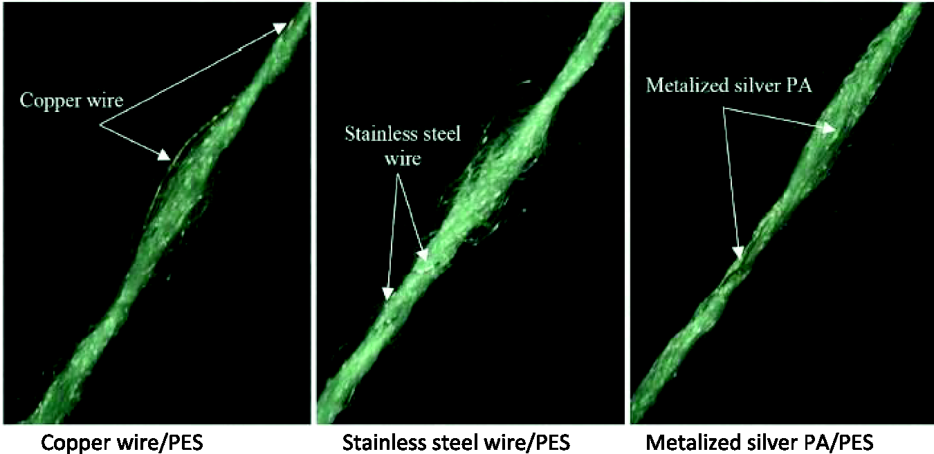
The process involves dipping fibrous structure into a solution of conductive polymer with subsequent drying as depicted in Figure 8. An example of such a yarn coated with PANI (polyaniline) is shown in Figure 9. The process of dipping and drying can be repeated several times to obtain the required conductivity or layer of various polymers.
Fabrication of functional threads. Schematic representation of the coating system for the preparation of conductive threads [87].
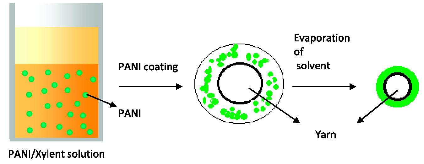
PANI coating on the yarn.
Various conducting polymers such as PANI [87,88], PEDOT: PSS [89], Ppy (Polypyrrole) [90] etc. has been deposited on yarn surfaces to render electrical conductivity. These developed yarns have been employed in making solar cells, sensors etc. [87]. Due to the intrinsic property of ICPs to combat EM radiations, fibers coated with ICP can be used to make textile-based EMI shield [91]. However, these conductive coatings suffered from nonuniformity and microporosity that’s not desirable due to the risk of exfoliation during textile processing steps [87].
Nanoparticles doped fibershierarchy is right. As this section head describes the synthetic spinning of fibers so should come under the section of “Rendering EMI shielding property at spinning stage”
hierarchy is right. As this section head describes the synthetic spinning of fibers so should come under the section of "Rendering EMI shielding property at spinning stage" The incorporation of functional materials into the dope solution of fiber before spinning allows the development of fibers with desired inherent functional properties. To achieve expected results, such nanomaterials must be uniformly dispersed in dope. Such a method is not only cost-effective but also process effective [88]. Sometimes to achieve desired results, large quantity of these nanomaterials is required (even > 30% concerning the matrix polymer) and strength of the fiber would be compromised to some extent in addition to increased cost [92]. Wet spinning and melt spinning are the well-established methods for developing fibers. The following section discussed briefly about the development of functional fibers for application in textronics, for instance, EMI shielding textiles.
Monocomponent fibers. Considering electroconductivity as a prerequisite for the preparation of EMI shielding materials, monocomponent yarns with inherent conductivity character have been prepared by wet and melt spinning. Such inherently conductive yarns can be employed for EMI shielding applications apart from other textronics applications. Inherently conducting polymers [93], carbonaceous materials [94] and metallic particles [95] incorporated during wet/melt spinning impart electrical conductivity to the insulating polymeric fibers. Depending upon mechanical and elastic properties, these fibers can be converted into fibrous skeletons such as woven, nonwoven, or knitted structures. Kim et al added PANI/Polypyrrole into dope of PP before melt spinning process but failed to attain appreciable conductivity as additive materials got aggregated and could not be interconnected to develop continuous conductive paths into the core of fibers [88]. Zhu et al developed fibers exhibiting outstanding indispensable properties such as elasticity and conductivity comparable to metals. These melt-spun fibers exhibited serviceable conductivity upon stretching. Such fibers were developed in two steps. In first step, hollow fibers were spun from a triblock copolymer, poly[styrene b-(ethylene-co-butylene)-b-styrene] (SEBS) resin. In the second step, the needle of injection was used to inject liquid metal alloy, eutectic gallium indium (EGaIn), into the core of the fibers. The electrical conductivity of the fibers (≈3 × 10⁻⁵ Ωcm) maintained under strain until it reached a level at which it started decreasing. The fibers maintained their tactile properties with a negligible effect on mechanical properties [96]. Polyacrylonitrile (PAN) fibers bearing silver and gold nanoparticles were developed by adding reagents for the preparation of respective metallic components into dope before spinning. But owing to the low quantity of synthesized metallic particles into the fiber matrix, a very small value of EMI shielding was observed in the frequency range of 2.5–3.5 GHz [92].
Lee et al developed SBS fibers by wet spinning. The fibers were dually decorated with silver nanomaterials by adding as-synthesized AgNWs into the dope solution before spinning followed by in-situ deposition of AgNPs onto the surface of developed fibers for enhanced electrical conductivity. The obtained electrical conductivity, 2450 Scm−1, along with good mechanical properties enabled these fibers to be employed in textronics [95]. Seyedin et al incorporated PEDOT: PSS as conducting component during the wet spinning of elastomeric fibers of polyurethane. The fibers possessed an electrical conductivity value of 166 Scm−1 with good mechanical and elastic properties [93]. Such filaments can be converted into fabrics for example knitted structures [97].
Bicomponent fibers. One of the revolutionary developments in the field of synthetic fibers production is the production of bicomponent fibers. Bicomponent fibers allow taking advantage of two or more polymers possessing, diversified physical or chemical characteristics in one filament. Such specialty fibers can be produced by selecting appropriate cross-sectional designed according to end requirements and are named accordingly: side-by-side, islands in the sea or segmented pie bicomponent fibers, and so on [98]. Schematic diagram for production of such fibers is presented in Figure 10. The development of bicomponent fibers for EMI shielding purposes makes use of some conductive material incorporated into filament. Such conductive nanomaterial is used to produce masterbatches of chips to ensure their uniform distribution into the polymer. As direct incorporation of these nanomaterials into extruder causes agglomeration [99].
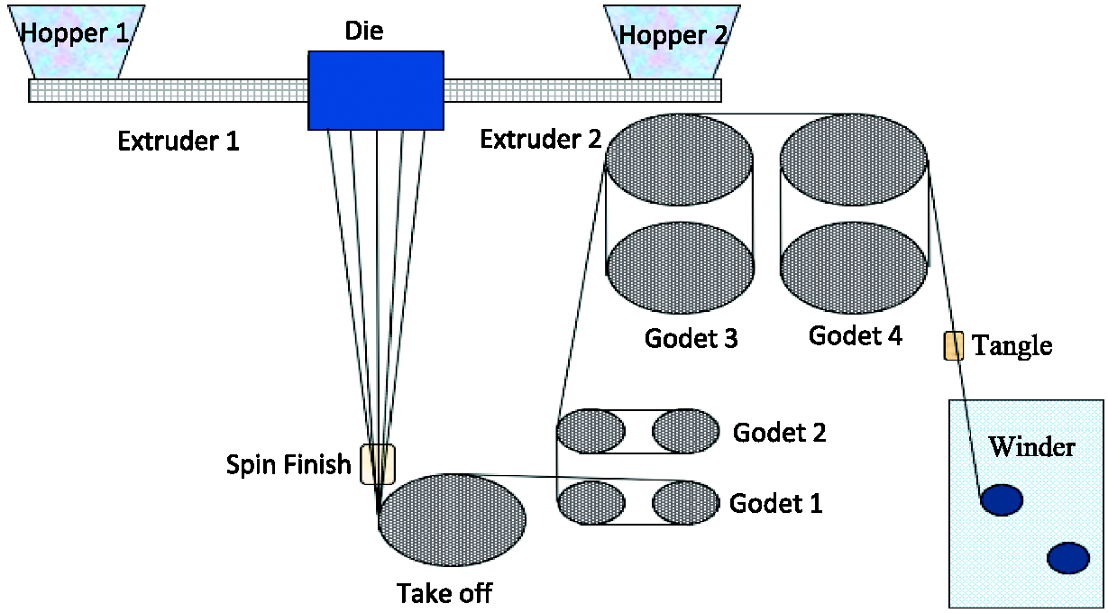
The schematic diagram to produce bicomponent yarn [99].
For example, carbon black in polypropylene (PP) and multiwalled carbon nanotubes (MWNT) in polyethylene (PE) were used to make conducting polymer composite that acted as the core of bicomponent fiber having polyamide 6 (PA6) or polypropylene (PP) as an outer covering (sheath). Such bicomponent fibers were produced on a pilot-scale bicomponent melt spinning equipment [100]. Iron oxide as conductive material was used as a conductive additive to the dope of polybutylene terephthalate (PBT) before its spinning. PET was used as sheath material. Multifilament yarns produced from these filaments were converted into knitted structures. EMSE values for loose and tight-knit fabric were 13.59 dB and 18.78 dB respectively at 30 MHz frequency [99].
Rendering EMI shielding property at fabric manufacturing stage
2D woven composite fabrics
Substantial research has been done in the past on EM shielding effectiveness of fabrics bearing conductive fibers [69,101]. Effect of type of fabric structure (knitted, woven), threads density, threads distribution and the number of fabrics plies on EMSE were investigated. The reader is referred to the work of Palanisamy et al. [81] for EMI shielding properties of different fabric structures made from both natural and synthetic fibers having an electroconductive component in them. Fabrics were made electroconductive in various ways. EMI SE values of 1-79 dB were obtained at high-frequency range depending upon the electro-conductive fabrics.
Fabric structure, number of layers and percentage of metallic yarn play a significant role in shielding performance [102]. Fabrics with more open structure act as a poorer shield than the fabrics with compact structures due to difference in the closeness of conductive elements. Fabric prepared from yarns having conductive core exhibited better shielding performance than the fabrics prepared from cover and plied conductive yarns due to high conductivity level [65]. But the associated problem with core-spun composite yarn is the malfunctioning of the fabric due to exposure of conductive core under certain conditions. Coating a hydrophobic material on the conductive component plays a role in solving this problem without compromising the shielding performance of the fabric [103]. Another associated problem with fabrics woven and knitted from metallic yarn has lowering of their SE after dyeing, washing and pilling test due to the migration of metal fibers of the yarn structure [104,105].
Lin and Lou prepared commingled fabrics on the rapier loom using yarn that was made on rotor-wrapping-twister from stainless steel, Kevlar and polypropylene. SE for these developed fabrics tested in the range of 30–3000 MHz was 30–60 dB [82]. Hybrid yarns composed of steel wire and polyester were also used to manufacture fabric containing different weaves. The best results of EMI SE were reported for the plain-woven fabric testing in the frequency range of 9 kHz to 3 GHz [65]. On the other handwoven fabrics bearing hybrid yarns having SS staple fiber exhibited SE in the range of 10-50 dB based on fabric structure and metal content [81]. Shielding through the reflection mechanism is not suitable for some of the applications like protection against radar unless conductive materials are mixed, for example; copper, stainless steel, and polyester containing composite yarns which can be produced on a hollow spindle twisting machine to serve the purpose. Plain woven fabrics developed from this composite yarn were tested for EMI SE property at the frequency range of 30-1500 MHz. It was shown that the EMSE of the metal composite fabrics could be tailored by modifying the metal grid size, geometry and aspect ratio. Moreover, fabrics having bare copper and insulated copper in their structure had the highest shielding efficiency up to 800 MHz and over 800 MHz to 1.5 GHz respectively. Capacitive coupling among the insulated copper yarn at higher frequencies (800-1500 MHz) was responsible for increasing SE by providing conductive paths [13]. Fabrics bearing carbon filament in their structure have been proved to be promising for shielding applications in low to medium frequency range [78]. Woven fabrics of various weave types including plain, twill, and satin, made from 100% carbon fiber exhibited SE in the range of when evaluated in the frequency range of 700 MHz to 3 GHz. Twill weave performed the best among these constructions due to the presence of a larger number of intersection points [106].
Among metallic hybrid yarn fabrics, yarns containing steel fibers are usually preferred for preparing EMI shielding fabrics. Therefore, Yang et al studied the effect of various structural parameters on shielding performance of fabrics and attempted to develop prediction models using extreme learning machine (ELM) algorithm taking different fabric structural parameters and their shielding performances at different frequency points as input and output variables respectively. The sensitivity analysis indicated that the prediction accuracy of the developed models had good reliability in accordance with the actual results [107,108].
Compound woven (3D) composite fabrics
In addition to 2D woven fabrics as mentioned in the previous section, work on 3D woven fabrics made from electroconductive composite yarns is available in the literature for EMI shielding. 3D fabrics are advantageous due to their lightweight, toughness, outstanding shear strength, and destruction tolerance. The multi-layered composition has drawn the attention of researchers to develop an EMI shield, as shielding performance improves in multilayered structures in comparison with monolayers. The larger surface area of these electroconductive multi-layered fabrics also plays a significant role in interacting with EM waves in addition to conductivity [109]. Chemical treatment of such electroconductive textiles to decorate their surface with nanomaterials can further tune their shielding performance to suit the requirements of different application areas. Perumalraj et al developed two-ply woven fabrics from copper and cotton yarn. An increase in the number of copper fibers per unit area due to the increase in cover factor, warp density, and weft density, and fabric layers lead to an improvement in shielding effectiveness of the fabric. The developed fabrics exhibited SE of 20–60 dB as tested in the 200-4000MHz frequency range [110]. Shielding effectiveness of five different 3D woven fabrics (angle interlock, orthogonal, multi-tubular spacer, cell-type spacer, and contour) using copper-wrapped hybrid yarn was compared in the X-band frequency range by Pandey et al. Their work indicated that in addition to imparting conductivity to the fabric, the fabric structure also plays a significant role in shielding performance in terms of reflectance, transmittance and absorption behavior due to larger surface area of 3D configurations. Toghchi et al developed 3D interlock woven fabric from cotton and silver yarn. Due to the increase of conductive yarn density through-thickness of the fabrics, the increase in EMSE was noted. Different shielding performance of fabric was noted in both warp and weft direction due to change in waviness degree of electroconductive yarns [111].
Knitted composite fabrics
As compared to woven structures, knitted fabrics are advantageous due to their various structural properties and ease of conformability into complex-shaped components. Knitted structures formed by a series of interlinking loops in the yarn. Certainly, the bends are so tight which result in mechanical failure of the incorporated conducting yarn which is risky to interlace in the same way of the component fabric yarns.
The metallic fiber in the knitted structure gives different EMSE depending upon the fabric structure and polarization type (vertical and horizontal). Ceken et al inserted steel yarn into acrylic knitted fabric in different directions and studied shielding property in the frequency range of 750 MHz–3000 MHz. The horizontal polarization demonstrated better shielding performance than vertical [77]. İlkan Özkan compared shielding performance of single jersey fabrics prepared from comingled conductive yarns having polyester and three different metals; stainless steel wire, copper wire, and silver-coated polyamide. All the fabrics exhibited shielding performance up to 35 dB in the frequency range of 0.8–5.2 GHz and the good antimicrobial property was exhibited by Cu and silver-containing fabrics. Effect of metal type on SE was found in the order: silver coated polyamide > SS > Cu. This was due to the highest electrical conductivity of silver and uniform distribution of the fibers. Although copper has higher conductivity than SS, due to lower strength of Cu than SS, its wires were broken during the manufacturing of hybrid yarn and fabrics that lead to discontinuity in the conduction path and hence lowered the SE [83]. Bahadir et al used stainless-steel wrapping polyester yarns to knit fabrics in different patterns like rib, panama, twill, and plain. Rib structure exhibited better EMSE than other fabrics [78].
Among the knitted structures, warp-knitted structures possess higher dimensional stability and are preferred for technical textiles applications. Lin et al developed warp knitted fabrics from hybrid conductive yarns in weft direction having SS yarn in the core while bamboo charcoal/nylon acting as sheath materials. To further impart elasticity to the fabric, rubber fibers along with PET were used in the warp direction. The fabrics not only showed good mechanical properties but also good elasticity and air permeability. Shielding efficiency of the fabrics varied with the number of fabric plies and plied angle as tested in the frequency range of 300 kHz to 3.0 GHz. The maximum SE obtained was 60 dB at 1988 MHz for 5 plies of fabrics arranged at angles 0°/90°/0°/90°/0° [112].
Nonwoven composites
Non-woven is a product in rapid evolution, which has already transformed its utilization, undermining the fabric structure in just a few years. The advantage is its low price, which has allowed the production of disposable products, considering that the fiber and the types of production offer an advantage to future applications assuring good permeability in addition to the mechanical resistance. The modified non-woven fabrics can be used for environmental shielding, electronic apparatus, shielded gaskets, cable shielding etc.
For shielding purposes, metallic fibers can be made part of non-woven fabrics during the batt formation process and extrusion in the case of spun-bonded non-woven fabric [76]. Nonwoven fabric transparent to EM rays can also be converted into EMI shield by coating RAMs on the surface of the fabric by various methods of which some are mentioned below along with obtained EMSE performance.
Sang et al prepared multifunctional piezoelectric Polyvinylidene fluoride (PVDF) based nonwoven composite by using AgNWs and Multi-wall CNTs (MWCNTs), by following dip drying and solution casting approach. The use of MWCNTs not only played their role in providing a conducting path for electrons but also enhanced the mechanical strength of the composite. The highest SE reported was 34 dB with thickness ∼391 μm. SE was reported to increase with the increase in the number of layers and hence thickness. Due to the presence of MWCNTs, the dominating mechanism of shielding was mainly by the absorption of EM rays. Although SER was also involved in EMI SE [113].
Platting time is positively correlated to the amount of metal deposited and hence EM shielding capability of the material. This effect can be depicted by the work of Lee et al. They used wet laid non-woven carbon fabric for Cu cladding and compared SE values for different platting times, pure Cu foil and pure carbon fabric. 70–90 dB SE at 1.5–10 GHz was the highest reported value and the shielding mechanism speculated was multiple internal reflections [114].
Electrospun structures. With rapid technological advancements, electrospinning (ESN) has been widely employed to engineer nanostructures such as nanowires, nanofibers, nanotubes and so forth [115,116]. Nanofibers arranged in web form are obtained by applying a high voltage between syringe (spinneret) and collector. Special characteristics that these nanoscale fibers owe are high surface area and high aspect ratio. These properties make them suitable for myriad applications such as filters, absorbents, wound dressing, tissue engineering
Recently, nanoparticles (NPs) incorporated into nanofibers endowed functional properties, for instance, EM shielding. In such a combination, the fiber matrix also protects NPs from corrosion and/or oxidation in addition to other improvements [116]. Fe nanoparticles in the carbon fiber matrix were developed by two-step electrospinning. Such a synergistic combination resulted in good absorption loss (reflection loss ≤−10 dB) in the frequency range of 2.2–13.2 GHz. Also, the carbon matrix acted as protection against the corrosion of iron [115]. Fe nanoparticles incorporated carbon nanofiber (prepared from PAN precursor) developed by electrospinning gave rise to a final 3D porous fibrous architecture. Impedance matching electric and magnetic loss, attenuation constant, and geometrical effect played their role in achieving excellent reflection loss of −56.6 dB at 4.96 GHz with a thickness of 4.29 mm [15]. Qiao et al developed carbon nanofibers by electrospinning and carbonizing process and tuned their EM attenuation characteristic by decorating them with nanoparticles of TiO2 (dielectric loss material) and Co (magnetic loss component). The metal salts for the synthesis of NPs were added in dope solution containing Polyvinylpyrrolidone (PVP) as a precursor of carbon fiber prior to the electrospinning process. The nanoparticles of TiO2 were uniformly distributed into the core and surface of the fibers while Co and CoO NPs were found to be embedded onto fiber surface. The three-dimensional assembly of fibers along with the combined effect of conductivity, polarization, and dielectric loss played role in attenuation of EM rays by absorption dominating mechanism (maximum reflection loss was 58.2 dB in X band) [117]. The same group investigated the role of carbonization temperature on EMI shielding performance of the same nanocomposite and concluded that 700°C was the optimum temperature to attain maximum absorption (63.2 dB) in X-band [118].
In addition to incorporating functional NPs into nanofibers for EM shielding, materials having inherent EM shielding properties can also be converted into nanofibers by electrospinning. Nanofibers of silicon carbide were developed from the polycarbosilane precursor by the electrospinning process. The schematic of the process is shown in Figure 11. These nanofibers were collected onto graphite paper. This scheme allowed tailoring of shielding properties by adjusting the mass ratio of polycarbosilane. 10 % PCS produced SiC nanofibers capable of showing a maximum of 57.8 dB reflection loss at 14.7 GHz with a thickness of 1.9 mm. Multiple reflections from SiC fibers and interfacial polarization from interfaces of SiC, graphite, and SiOxCy were responsible for EM waves attenuation [43]. Electrospun nonwoven fabrics prepared from silica using Tetraethyl orthosilicate (TEOS) sol containing magnetic nanoparticles of Fe3O4 were subsequently decorated with PPy by in situ polymerization. To further tune the shielding properties of the fabric, reduced graphene oxide was deposited by dip dry method. Such a core-shell flexible assembly of shielding materials exhibited a shielding efficiency of 32 dB in the X band with electrical conductivity of 0.71 S/cm [119].

Pictorial presentation of developing SiC nanofibers by electrospinning, pyrolysis and annealing [43].
Electrospinning products of inherently conducting polymers exhibit exceptional electrical and optical properties. Doping allows tuning such properties for myriad applications including chemical and biological sensors, LED, rechargeable batteries, wearable electronics, tissue engineering, EMI shielding etc. Electrospun PEDOT fibers doped with tosylate were developed by Gramont et al, adopting a two-step procedure [120]. Lee et al developed nonwoven web by electrospinning of PPy exhibiting electrical conductivity of 0.5 Scm−1 [121,122]. These electrospun fibers possessed stretchability as demanded by some applications.
Fabric reinforced composites
EMI shielding composite structures bearing fabrics as one of the composite components have also been developed to suit different shielding structural requirements. Such fabric reinforced polymeric composites owing to lightweight and excellent structural properties are suitable for load bearing applications in critical sectors such as aeronautical, defense and automobile. To develop composite structures knitted, woven and their combinations have been used as reinforcement.
The following section is a brief detail about such composites.
Conductive knitted fabric reinforced composite materials. Knitted fabrics made of elite fibers such as carbon, Kevlar and glass etc. have been used as reinforcement to prepare composites to develop structural materials for high end technical applications due to light weight and excellent physical properties. These insulating yarns are transparent to EM radiations. In order to serve them as a shielding material, these have been made electro-conductive by converting them to hybrid yarns using metallic fibers such as copper and steel. Such composites have been evaluated for their electromagnetic shielding property in various frequency ranges.
Cheng et al used PP as matrix material and knitted glass fabric as reinforcement to develop EMI shielding component incorporating copper wires as conductive material. Effect of varying copper content on EMSE properties was evaluated in frequency range of 300 kHz to 3 GHz. With increase in frequency, a decrease in EMSE was observed while EMSE increased linearly with increase in copper content. The laminate having highest amount of copper exhibited EMSE of 101.60 dB at 0.3 MHz and 33.01 dB at 3000 MHz [80].
Knitted fabrics developed from uncommingled yarns SS/PP, Cu/PP, SS/C/PP, Cu/C/PP and Cu/K/PP in which content of metallic fillers was varied have been employed to develop thermoplastic laminates of 3 mm thickness by compression molding technique. EMSE was found to be increased with frequency as tested over 350–3000 MHz. Carbon and copper were proved to be suitable for shielding at low frequency range while for higher frequency ranges steel was proposed to be suited [68].
Conductive woven fabric reinforced composite materials. Composite fabrics, made from metallic yarns as one of the structural components, reinforced in epoxy resin exhibit varying EM shielding properties with fabric structures due to variation in content of metallic component [123]. Though, carbon fabrics owing to inherent conductivity can be employed for shielding applications but its conductivity in not enough to meet the minimum requirements for shielding applications. In this direction, carbon based materials have been employed to prepare composites.
For example, MWCNT were anchored on surface of carbon fabric to prepare fabric preforms that have been reinforced in epoxy resin to form prepregs. Subsequently, these prepegs were arranged to form multi-layered structure that was further treated in compression molding. MWCNT not only improved interlaminar shear strength but also EMI shielding properties of the composite from −29.4 dB for CF/epoxy composite to −51.1 dB for CF-MWCNT/epoxy multiscale composites of 2 mm thickness as tested in X band of frequency [124]. Carbon micro particles dispersed in epoxy resin were applied on surface of cotton fabric by hand lay-up process. With 8% carbon micro particles the composite provided 23.13 dB shielding as tested in X-band frequency range with enhanced mechanical properties [125]. Glass fabric/epoxy composites containing conductive multi-walled carbon nanotubes as electrical shielding materials exhibited more than 90% shielding capacities in 300 MHz to 1 GHz frequency range [126]. In order to provide shielding against wider band width radiations, mixture of RAMs is employed. Duan et al developed composite fabric having 30% stainless steel content in its structure by coating epoxy resin containing graphene, carbon nanotubes, nano-nickel and ferrite in different combinations and varying coating layers to give different values of shielding effectiveness in frequency range of 1-18 GHz [127].
When the fabrics incorporated with nanomaterials are arranged in multilayer architecture, shielding performance is enhanced by many folds. In this perspective, Bhingardive et al designed a multi-layered composite assembly the outer layer of which was formed of Polyvinylidene fluoride (PVDF)/Carbon fiber (CF) and the inner layer consisted of melt mixed PVDF/MWCNT. To enhance the absorption properties of the outer layer, nanoparticles of iron were adhered on the surface of carbon fiber mat by electroless plating. This laminate was prepared by compression molding and was denoted as Polyvinylidene fluoride and iron composite (PFe) @ carbon fiber and polyvinylidene fluoride composite (CFP). The interfacial polarization created between the carbon fiber and iron nanoparticles resulted in formation of conducting network when stacked into a layer, which promoted absorption of EM waves. The PVDF/MWNT composite film was placed in between PFe @ CFP layers to create a multilayer sandwich structure by hot pressing. This sandwich structure (denoted as PFe @ CFP-PVDF/MWNT-PFe @ CFP) of thickness 0.6 mm exhibited SE of −54 dB at 18 GHz as compared to the controlled sandwich structure (CF mat is sandwiched between two PVDF films). The underlying principle behind the structure is the presence of conducting (MWNT/PVDF) material possessing reflection and magnetic material (Fe @ CF) possessing absorption properties [128].
Multi-layered fabric structures. EMR shielding performance of an article varies with structure/morphology and thickness of the article while frequency being another variable. With the increase in thickness of shielding article, its efficiency to act as an obstacle for EM rays increases. Multi-layered textile architectures consisting of coated textiles and/ or specific textile structures of different magnetic permeability and electric permittivity, give rise prospect to make such a shielding article that meets the expected shielding properties effectively. Researchers have developed multi-layered textile architectures and observed varying EM shielding performance in relation to variation in their layered textile components.
Carbon fabric, nylon nonwoven fabric and warp-knitted spacer fabrics of polyester have been used to make composite structure containing Polyurethane (PU) foam by varying structural arrangements. Apart from exhibiting other outstanding properties, the composite possessed shielding effectiveness of 50 dB at 2 GHz; an attenuation rate of 99.999% that is considered a good practical application value [129]. Multi-layered textile architectures were developed by plying up different electro conductive textile structures including knitted fabrics and woven fabrics developed from metal blended PET or PET yarns, aluminum coated fabrics and PANI coated fabrics. These hierarchal structures exhibited shielding efficiency ranging from 16 dB to 60 dB in frequency range of 8 GHz to 18 GHz, by placing electro conductive textiles in different ways [130].
Rendering EMI shielding property to the developed fabrics
Anchoring nanomaterials
After a great revolution brought by nanotechnology, nanoscale particles are widely adopted by scientists in the last two decades especially by textile researchers due to their enhanced characteristics to develop multifunctional textiles. These nanomaterials have no affinity towards the textile substrate, therefore they have to anchor on the textile substrate by different techniques. The techniques to anchor nanomaterials capable to curb harmful high-frequency EM radiations onto textile surfaces are mentioned below.
Some of these techniques involve decorating the as prepared nanomaterials onto/into the surface of the polymer matrix. This is advantageous as high-quality particles can be made part of the polymer matrix. But the associated problem with this method is the incompatibility of the particles with the polymer that leads to non-uniform distribution of these NPs in the matrix [131]. The formation of large clusters of these NPs results in failing to attain the required properties. To overcome this problem, stabilized and homogenized dispersion of NPs is prepared [132].
Some of the other techniques involve synthesis and depositing nanomaterials directly onto/into the polymer matrix in one step, such as electrochemical method, PVD and in-situ synthesis, etc. These methods allow synthesizing stabilized nanoparticles with uniform distribution of NPs.
Pad-dry-cure method. Nanoparticles capable to intercept EM rays can be anchored to fabric using cross-linking agents to impart EM shielding property to the fabric by adopting the pad-dry-cure method. The cross-linking agent makes three-dimensional networks onto the fabric surface in which functional moiety gets entrapped. This process has ease in application with a negative effect of the harsh handle which can be minimized using softeners preferably silicone softeners. Different wt% of nanoparticles of zirconia were attached by Gashti et al on the surface of the wool knitted fabric by citric acid through the padding process. Apart from EMSE, other properties including flammability, hydrophobicity, and optical properties were also studied. The highest reported EMR was ∼68dB at frequency 5600-5800 MHz with 9% zirconia [133]. Similarly, zirconia nanoparticles were decorated on the surface of cotton fabric by cross-linking agents (maleic acid) to prepare multifunctional EMI shielding fabrics [134]. Carboxyl and hydroxyl functional groups were introduced by citric acid and maleic acid. The presence of these functional groups within an absorptive material provided additional polarization centers to enhance the EM wave absorption [135]. Another way of utilizing cross-linking agents is aiding electroless deposition of metals. Zhao et al anchored AgNPs on cuprammonium fabric by 3 different carboxylic acids that acted as catalytic sites for growing nickel nuclei during electroless deposition. SE higher than 26.3 dB was reported by the authors [136]. Haji et al. attached amine-functionalized carbon nanotubes on plasma-treated PET fabric in the presence of acrylic acid. The developed fabric was evaluated for shielding from EM waves in the X band (minimum reflection loss of about −18dB at 11 GHz) [137]. Simayee and Montazer decorated PET fabric with carbonyl iron and nano carbon black in the presence of silicone softener by pad-dry-cure method followed by Al metal sputtering for attenuation of EM waves in X-band [41].
Coating. Coating of functional materials on fabric surface is done by knife-over-roll coating and screen coating on industrial scale. Knife-over-roll is among the most cost-effective and facile methods to prepare coated textiles of tunable coating thickness on a commercial scale. To enhance flexibility of coated fabrics, such polymers can be made part of the coating that are inherently elastic in nature such as polyurethane and rubber latex. Ghosh et al applied ∼0.20 mm thick coating of conductive carbon black on cotton fabric using PVA and natural rubber latex. By increasing the content of conductive carbon black from 20phr to 40phr, an increase in SE (absorption dominating mechanism) from 20.8 dB to 37.7 dB was noted over the frequency range of 8–12 GHz. This was attributed to the formation of a three-dimensional conductive network over fabric surface and porous architecture covering all voids of the fabric [138]. In another study, macro carbon particles were coated on cotton fabric using PVA and natural rubber latex. With an increase in coating thickness from 0.2 mm to 0.3 mm, SE increased from 21.5 dB to 30.8 dB. The uniform distribution of agglomerates of carbon particles was also observed due to the poor dispersion of carbon particles in Natural rubber (NR) latex. However, NR latex gave flexibility to the coating layer [139]. Gupta et al. coated cotton woven fabrics on both sides with Ni–Zn ferrite nanoparticles and carbon black as fillers in a polyurethane matrix. Due to the combined effect of conductivity, permeability, and permittivity, the coated fabrics at a thickness of 1.86 mm offered approximately 40% reflection, 20% transmission, and 40% absorption in X and Ku frequency bands [30].
Some researchers have tried to enhance the durability of EMI shielding nanomaterials by chemical bonding between NPs and the substrate. By thiol-ene click chemistry, Wang et al modified cotton with 3-mercaptopropyltriethoxysilane (MPTES) and used conductive thiol-modified reduced graphene oxide (M-rGO) along with waterborne polyurethane (WPU) as a carrier. Both ends of WPU molecules bear ene groups that acted as a bridging group between thiol groups of MPTES modified cotton and thiol groups of M-rGO via synchronous thiol-ene click reaction (covalent bond formation) respectively as shown in Figure 12. The prepared emulsion was applied to both sides of the fabric by screen coating [140]. Similarly, Wang et al employed the same method of synchronous thiol-ene click chemistry using magnetic filler (nickel ferrite) along with conductive filler (thiol-modified reduced graphene oxide M-rGO) to decorate MPTES modified PET. Reaction chemistry, emulsion polymer, and its application methods were the same as adopted for MPTES modified cotton [141]. In the case of polyester, the highest SE was 53 dB (at 0.3 mm thickness) due to the synergistic effect of both types of materials, while in case of cotton, it was 48.1 dB (at the thickness of 1 mm) due to the presence of only one type of material in X-band frequency. The contribution of SEA to SET was higher than SER due to stronger dielectric properties. Their work also indicated that required SE can be obtained at lower thickness of coated materials when using synergistic combinations of materials as compared to monocomponent coatings.

Schematic of developing modified rGO/WPU fabrics along with their employment [140] [with the permission of Elsevier Publisher].
Vacuum deposition. Two main techniques based on vacuum deposition or making thin films of nanomaterials are known as chemical vapour deposition (CVD) and physical vapour deposition (PVD). The substrate surface should be completely cleaned for the deposition of nanoparticles otherwise the deposited layer falls off easily. Moreover, specialized equipment is required for the process to carry out and the process cannot be controlled efficiently and hard to adopt on a larger scale [142].
Physical vapour deposition. In the PVD technique, physical processes are employed such as evaporation and sputtering. Besides, many sputtering techniques are used to form a plasma by collision effects of the gases in the background [143]. Esen et al decorated cotton/elastane blended fabrics with Al and Zn by this method and studied the absorption and reflection behavior of EM waves in different radar frequency bands. Zn coated fabrics were found to be better than Al coated fabrics in terms of EMI SE in the frequency range of 3-18 GHz with absorption dominating mechanism [144]. Similarly, titanium metal being the lightest weight metal among commonly used metal was deposited by this method on cotton/polyamide blended fabrics. The fabrics exhibited excellent EM wave absorption properties in C-band (1-6 GHz) [143].
By the sputtering method, it is possible to deposit metallic as well as semiconductor and dielectric layers. An additional advantage of the method is the good adhesion of deposited layers to the substrate [145]. Kim et al. adopted a direct current magnetron sputtering method to decorate polyimide fabrics with nanofilms of two metals silver and copper one after another. The shielding efficiency of such composite fabrics was greater than 55 dB at a frequency range of 10 MHz–1.3 GHz [146]. Wang L. et al. deposited nano Cu film on the surface of polyester fabric at ambient temperature. In addition to possessing favorable shielding efficiency and electronic conductivity, the fabrics were also capable to provide excellent shielding against UV radiations. Another notable element was the dependence of shielding effectiveness on the substrate especially its porosity [147]. Jiang et al coated Al, Cu and stainless steel onto PVA coated cotton fabrics by magnetron sputtering. In addition to providing other properties, the fabrics exhibited acceptable shielding at the frequency range of 300 kHz–1.8 GHz. 30 dB shielding effectiveness was achieved for copper-coated fabrics while poor shielding properties were exhibited by SS and Al coatings [148]. Metallization of PP nonwoven textile substrate by zinc magnetron sputtering could act as a shield to attenuate EM waves in the frequency range of 30 –1300 MHz The attenuation level could be realized by obtaining SE value (over 50 dB) with surface resistance in the order of 103 Ω. Moreover, the value of SE is influenced by the three-dimensional assembly of the surface [145].
Nanocomposite structures can be constructed on textile surfaces by combining more than one technique. Simayee and Montazer coated mixture of carbonyl iron and nano carbon black (both components possess wave absorption properties) on PET fabric by pad-dry-cure method followed by application of wave reflective metallic component aluminum by sputtering. The reflection loss was lower than −5.9 dB in the entire frequency range of X-band [41].
Chemical vapour deposition. In the CVD technique for depositing nanomaterials, the design of resulting thin film is comprehended by the chemical reaction between precursors. Usually, hot surfaces of the substrate or a specialized design deposition chamber are required for such reactions. One such example of employing the CVD technique for constructing EMI shielding can be taken from the work of Ding et al., who coated pyrolytic carbon on Al2O3 fiber-based woven fabric and studied influence of coating time on complex permittivity and EM wave absorption properties [46].
Electroplating method. Its electrochemical method for anchoring nanomaterials onto the fabric surface. This technique is restricted to conductive fabrics only such as fabrics made from carbon fibers as the process is carried out with the aid of electricity for deposition of metallic particles. However, insulating fabrics can be made conductive to adopt this method. Ali et al. converted insulating fabric (cotton/nylon/elastane blended fabric) into conductive fabric by in situ deposition of copper nanoparticles for electroplating of copper. EMSE of the fabric increased from 24 dB to 52 dB for CuNPs fabric and copper-plated fabric due to an increase in conductivity as tested in the frequency range of 30 MHz–1.5 GHz [71]. An et al. attempted to develop a flexible shielding fabric (EMI SE = 59.3–70.2 dB, within 300 kHz to 1.5 GHz) by the electroplating of Ni–Fe–P alloy on copper modified PET fabric [149].
Electroless plating. Textile fabrics have been coated with metals such as aluminum, copper, nickel, silver and a combination of these on an industrial scale. The process is simple and involves redox reaction for metallization of textile surfaces without the aid of electricity and allows uniform distribution of particles on edges, inside holes and irregular structures that are usually difficult to cover by electroplating. Proper cleaning and pre-treatment of the fabrics are required before the process. However, electroless platted fabric surfaces suffer from fracturing effect depending upon ductility and brittleness of metal used. Moreover, tensile strength is negatively affected while other physical properties remain the same or become better [150]. Literature has revealed that different textile skeletons have been modified by this process such as nonwoven [151]. Fabrics made from natural, synthetic and high-performance fibers such as cotton, polyester and glass have been modified by this process. The compactness of the fabric is directly related to the EMSE performance of the fabric in electroless plating [152].
Xing et al prepared flexible non-woven carbon fabric for EM shielding purposes. Silver nanoparticles were deposited on fabric surface by electroless plating and interconnected by applying pressure at 180°C in the presence of polyimide film. This interconnection of NPs provided more contact points for electrons traveling and hence played a significant role in achieving intriguing electrical conductivity. Subsequently, waterborne PU by dip-coating was applied for protection on silver. SE for material with pressing was 37.5% higher than that without pressing as tested in the frequency range of 30-1500MHz [151]. On the other hand, electroless plating of silver onto PET fabric using silver nitrate mixture for activation resulted in EMI shielding fabric possessing 55 dB SE in the frequency range of 100–1500 MHz [153]. Electroless plating of Cu on PET fabric gave EMSE ranges from 30–59 dB in the frequency band of 100 MHz to 1800 MHz depending upon different reaction parameters and pre-treatment agents [150]. While electroless deposition of nickel on PET fabric using different activation solutions gave 125 mΩ/sq surface resistance and 40–60 dB shielding effectiveness over frequency band 0.3–3000 MHz [154].
Click electroless plating capable of eliminating the activation step of typically employed electroless plating procedure was adopted by Moazzenchi and Montazer. They deposited nickel onto the polyester fabric by directly immersing the fabric into the solution containing reagents for the preparation of NiNPs. The reaction solution was heated to form NiNPs on the fabric surface to render conductivity below 2Ω with SE = 30–35 dB over 8.4−12.4 GHz [155].
Gao et al deposited polydopamine on PP nonwoven fabric via the self-polymerization method followed by adsorption of AgNPs precursor. AgNPs were formed and bonded by coordination after getting completely reduced. Subsequently, the hydrophobic character was endowed by further treating the fabric with fluoro compounds. The schematic of the process is presented in Figure 13 and SEM images of the fabrics prepared under different dipping times in AgNPs precursor are presented in Figure 14. Such treatment made the fabric electroconductive with electrical conductivity of 4000 S/m and SE of 48.4 dB [156].

Schematic for decoration of PP/PDA/silver NPs/PFDT on fabric surface [156] (with the permission of Elsevier Publisher).

SEM images of the PP/PDA/AgNPs/PFDT-50 composite fabric developed under different dipping time of PP/PDA in the Ag precursor. (a and a′) 20 min, (b and b′) 40 min and (c and c′) 50 min; (d) Elemental mapping of the selective region (the red rectangle in c) of the PP/PDA/AgNPs-50/PFDT-50 [156] (with the permission of Elsevier Publisher).
Silane compounds have been employed to improve the durability of metals decorated on fabric by an electroless plating method. Moreover, they also gave the advantage of eliminating the need for noble metal catalysts for the activation step. For example, Lili et al. covalently attached 3‐mercaptopropyltriethoxysilane with PET by a condensation reaction. The end bearing mercapto group captured silver by chelation that acted as catalytic sites for electroless plating of silver. The mechanism is shown in Figure 15. Achieved silver weight on the fabric was 25 g/m2 that gave fabric SE of >30 dB tested in 1 MHz to 5000 MHz frequency [157].

Schematic of bonding silver to fabric for electroless plating initiation.
Wang et al modified PAN sequentially with (3-aminopropyl) triethoxysilane (APTES) and 3-mercaptopropyltriethoxysilane (MPTES). The SE effect of 40–80 dB on silver plated modified fabric against the frequency range of 30 kHz to 3 GHz was reduced to 35–50 dB after 30 standard washing but still, it remained fairly good. The average surface resistance after silver plating was around 40 mΩ/sq [158]. Lu et al employed Ag, Au, or Pd activator for electroless deposition of copper on modal fabric modified with 3-aminopropyltrimethoxysilane. Silver-based activator was found to be more favorable among these activators to prepare EMI shielding fabric that was higher than 40 dB in the frequency range of 100 to 1000 MHz [159].
Silane treatment can also be done after the metal coating process that will improve the adhesion of metal nanoparticles with the substrate. Periyasamy et al coated PET milife fabric with copper by electroless plating method followed by silane treatment by a sol-gel method employing three different silanes. The silane treatment enhanced the shielding performance of copper-coated fabrics as shown in Figure 16(a). Coating Triethoxy phenyl silane (PhTES) on copper-coated fabrics resulted in doubling the shielding performance of the fabrics due to the presence of aromatic ring in the structure that played its role in attenuating EM radiations by bonding interaction. On the other hand, reduction in SE was observed after TEOS and Octyltriethoxysilane (OTES) coatings on copper-coated fabrics that might be due to the presence of an aliphatic chain that is not capable to interact with EM radiations, Figure 16(b). The air permeability of the fabrics was reduced but water permeability was not affected much [160].
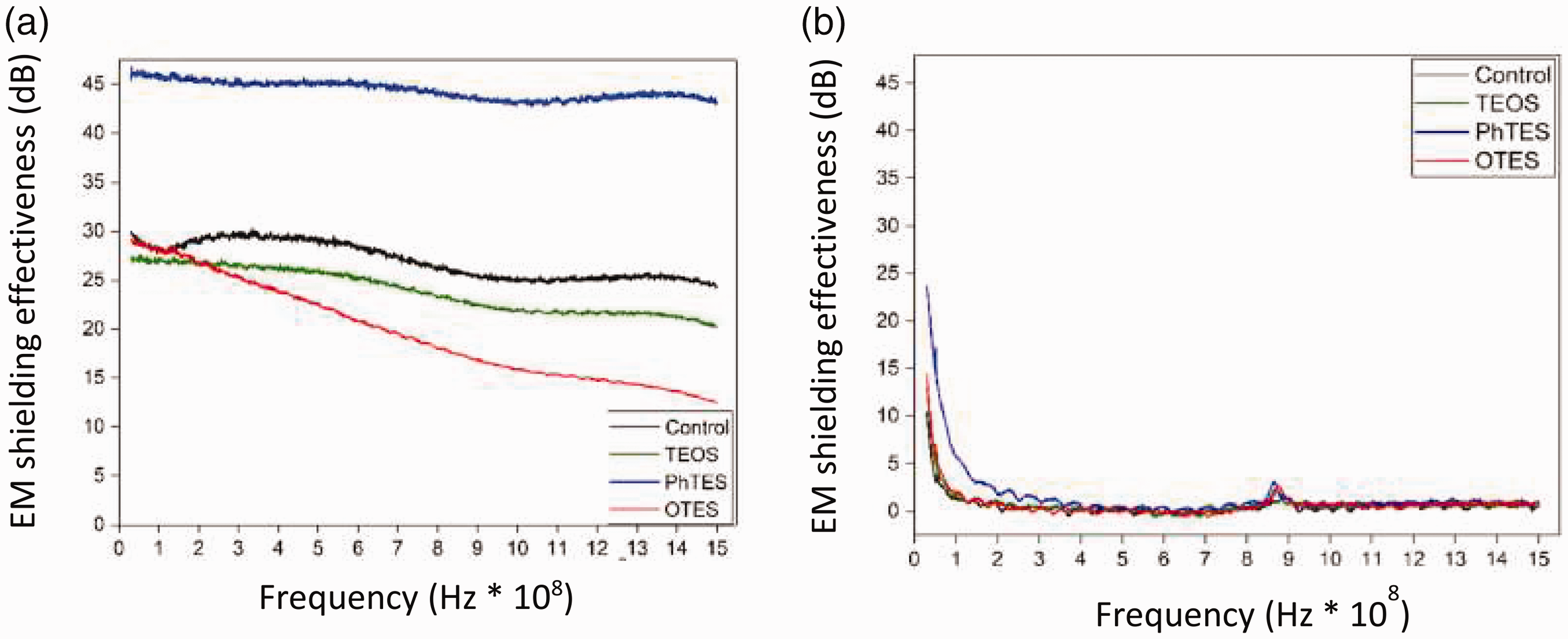
(a) SE of copper coated silanized fabrics (fabric without silanization is denoted as control), (b) SE of only silane coated fabrics [160] (with the permission of Elsevier Publisher).
Electroless plating of nanoscale composite materials. The merger of single components to form hybrid nanomaterials are set to gather every crucial property in a single composite for improved/enhanced shielding effectiveness. The metal plating process can be used in combination with ICPs to enhance shielding performance. Zhao et al decorated surface of cuprammonium fabric with PPy and CuNPs as shown in Figure 17 and deposited PPy by in-situ polymerization followed by electroless Cu plating. PPy stayed onto the fabric by hydrogen bonding due to the presence of >C-OH and –NH groups onto fabric and PPy respectively. 1.52 µm thick layer of PPy was proposed to be enough to develop a conductive path by interconnecting the fibers. PPy coated fabrics were modified with APTMS before electroless plating of copper. SE of ≈26–46 dB for the copper-plated fabric was improved to 30.3–50.4 dB due to the presence of PPy on copper-plated fabrics as tested in the frequency range of 30–1000 MHz. The sheet resistance of the developed fabrics was 85.8 mΩ/sq [161].

Schematic illustration to develop fabric based CF/PPy/copper composite [161] (with the permission of Elsevier Publisher).
Ding et al deposited PANI on PAN fabric by in situ polymerization followed by electroless plating of nickel-tungsten-phosphorus alloy. The developed composite layer onto PAN fabric renders SE 65–103 dB over the frequency range of 0.3–3000 MHz due to the synergistic effect of wave absorbing material (PANI) and wave reflecting material (nickel alloy) [162]. Wang et al carried out in situ polymerizations of PANI on polyimide fabric followed by electroless deposition of an alloy comprising nickel-cobalt-Ferrum-phosphorus to prepare fabric exhibiting SE of 40.5–69.4 dB at X-band frequency range [163]. Such a synergistic effect was obtained by Ding et al by grafting graphene (wave absorption material) on the fabric followed by electroless plating of an alloy comprising nickel, tungsten, and phosphorus. This composite fabric exhibited EMI shielding of 72 dB in 2–18 GHz frequency [12].
Alloy electroless plating. As an outstanding comprehensive shielding performance cannot be attained by single plating metal layer meeting demands of the high-end applications such as aerospace and military. Therefore, alloy electroless plating has become an effective method and is favored by many researchers. Electroless plating for deposition of the alloy is adopted by some researchers, most of them are in Ni–X–P form where X is W [162], Cu [164], Fe [165], Co [166] and Mo [167]. These alloys were deposited on other substrates than fabrics but decorating the fabric with these alloys will enhance EMI shielding properties of the fabric. Zhang et al platted PET fabric with Ni-P-Fe3O4 composite possessing SE higher than 45 dB over the frequency range of 2250 to 2650 MHz. However, the composite layer suffered from poor abrasion resistance due to the microcrystal hierarchy as compared to Ni-P plated fabric [168]. For the protection of these metallic layers, protective coatings are applied on top. Zhu et al deposited Cu–Ni–Gd alloy on linen fabric by electroless plating followed by self-polymerization of dopamine as a protective layer. The fabric was capable to protect from low-frequency radiation (SE = 42.0–49.4 dB) in the frequency range of 30–4500 MHz [169]. Bi et al employed an alkoxysilane, 3-aminopropyltrimethoxysilane (APTMS) for protection of Co-Ni-P platted tencel fabrics exhibiting SE of 40.1 dB in the radio frequency range of 30–1000 MHz [170]. APTMS is not friendly to human skin when coming in contact therefore, for preparing such fabrics that come into direct contact with human skin, polydopamine is preferred as a protective coating [169]. Another cellulosic fabric ramie has also been modified by electroless plating of Co-Ni-P alloy. Fabric exhibited outstanding corrosion resistance along with SE of 42.27 66.76 dB in 30 to 6000 MHz [171].
Electroless plating in combination with other techniques. To develop hierarchal structures of metals and to achieve enhanced electrical conductivity, metal deposition techniques can be employed in combination. For example, Ali et al adopted electroless plating along with in situ deposition of metallic nanoparticles to prepare EMI shielding fabrics. The fabric surface was decorated with silver and copper nanoparticles by in situ deposition of particles which provided active sites for electroless deposition of copper. Fabrics prepared with copper electroplating over silver exhibited higher surface resistivity of 20 Ω and EMI shielding of 75.53 dB over the frequency range of 30–1500 MHz [172]. This higher conductivity could be attributed to a combination of the highest conductive metals, copper, and silver.
Layer by layer assembly. Flexible and multifunctional textiles are highly demanded, especially for wearable textiles. Layer by layer assembly technique allows depositing multiple materials (organic/inorganic hybrid materials) onto substrate step by step and fabricating hierarchal composite layers to combat EM waves. This technique allows for higher loading levels of nanomaterials. Zou et al developed a layer-by-layer structure on wool fabric comprising PPy and graphite oxide. The prepared fabric exhibited moderate EMI SE (12.1 dB) in dry state and increased up to 18 dB in wet state as water can cause increase in SE due to conductivity [173]. Tin et al coated graphene on cotton fabrics using layer by layer (LbL) electrostatic self-assembly (ESA) method. The process involved dipping cotton fabrics into negatively charged poly (sodium 4-styrenesulfonate) (PSS) followed by the application of a positively charged chitosan layer containing graphene (CSG). When cotton was soaked into the PSS solution, the surface of cotton was covered with negatively charged PSS due to the presence of –SO3– groups. Upon subsequent dipping of cotton into chitosan solution, positively charged –NH3+ groups of chitosan got attached to negative groups on the cotton surface. This resulted in covering the cotton surface with a positive charge and this cycle was repeated to the desired number of layers. The fabrics were coded as PCSG1, PCSG3, PCSG5, and PCSG10 for 1, 3, 5, and 10 coating layers respectively. Electrical conductivity increased with increase in coating cycles and hence the shielding effectiveness. Up to 10 coating layers onto cotton fabric exhibited shielding effectiveness of 30.04 dB in the frequency range of 30 MHz to 6 GHz and electrical conductivity of 1.67 × 10³ Sm−1. This high shielding performance could be attributed to the multiple reflection and scattering of waves produced by the multi-layering of graphene [174].
Lan et al developed the hierarchal structure of highly loaded CNT on cationized macro-porous cellulosic fabrics by capillary assisted LbL technique. The higher loading of CNT was made possible by eliminating the rinsing step as employed in the traditional LbL assembly method. The fabric was dipped in the aqueous dispersion of CNT followed by dispersion in poly(allylamine hydrochloride) (PAH) solution containing NaCl. The CNT got adsorb on the fabric surface due to the ubiquitous capillary action of the fabric. This cycle was repeated several times without rinsing with distilled water as an intermediate step. The deposited CNT stayed on the fabric due to electrostatic interaction between negatively charged carboxyl moieties on CNT and positively charged amine groups on PAH. This method allowed increased shielding performance of 11.9 dB in X band of frequency and increased electrical conductivity of 5.3 Sm−1 after 30 coating cycles as compared to SE of 0.5 dB with electrical conductivity of 0.4 Sm−1 after 15 coating cycles achieved by traditional LbL assembly method. The improvement in shielding performance and electrical conductivity were mere because of the higher loading level of CNT (70.9 wt%). Due to such a higher loading level of CNT, the flexibility of the fabric was not much affected and retained some air permeability [8]. These could be possibly due to the selected fabric structure that was macro porous although the authors didn’t mention the exact type of fabric structure and its specifications selected for this work.
Zhang et al adopted the LbL assembly method along with the dip-coating method to construct a multilayer structure on cotton, consisting of polyethyleneimine/phytic acid (PEI/PA) and silver nanowires (AgNWs). This multi-layered structure held on the fabric by electrostatic interaction and hydrogen bonding. For LbL assembly, the solution of PEI was taken as a cationic solution while PA solution was taken as an anionic solution. The fabrics after 8 cycles were selected for the deposition of AgNWs by dipping in 0.8 wt% of AgNWs suspension in alcohol for various times to attain multiple add-ons. At the loading of 24.2 wt% of PEI/PA and 7.5 wt% of AgNWs, the electrical conductivity of the fabric reached to 2416.46 Sm−1. Also, the prepared conducting polymeric textile composite was able to combat EM radiations by absorption dominating mechanism (EMISE = 32.98 dB) over the X band frequency range due to the formation of the interconnected conductive network [175].
Miscellaneous methods. Some literature shows isolated reports on the development of EM shielding textiles using creative or unfamiliar fabrication methods due to the significance of EM shielding coated textiles. One such example comes from the work of Luo et al who developed a hierarchical structure of AgNPs and Fe3O4 NPs on PP fabric using polydimethylsiloxane (PDMS). They firstly deposited AgNPs on PP fabric (pre-treated with oxygen plasma) by dip-coating/in situ deposition method and then Fe3O4 NPs in PDMS were applied using spray coating on both sides of the fabric. PDMS not only provided adhesion of NPs with fabric but also endowed the fabric composites with super hydrophobicity. This multifunctional fabric exhibited high conductivity (up to 108.8 S/cm) containing EMI shielding ∼56.1 dB in the X band. Multiple absorption and reflection were responsible for shielding against EM radiations due to Fe3O4 NPs and AgNPs respectively [176]. Nanoparticles in their dispersion form, also known as conductive ink, have also been applied to textile substrates. The decorated fabric can also be modified to render multifunctionality in addition to EMSE. Jia et al used conductive ink containing AgNWs to impart conductivity to PET/spandex blended fabrics pretreated with NaOH using a drop-casting method. For the protection of AgNWs from oxidation, protective coatings were applied to the fabric comprising carbon nanotubes, polytetrafluoroethylene nanoparticles, and fluoro acrylic polymer [177]. For some samples, PU was synthesized onto the surface silver-coated fabrics which exhibited 63.9 dB EMI SE at 0.6 mm thickness. A remarkable finding was reported by authors that, with the increase in loading of AgNWs, a substantial increase in SEA was observed with a slight increase in SER [178]. On the other hand, CNT based coated fabrics demonstrated 51.5 dB shielding effectiveness as compared to only AgNWs coated fabric (39.6 dB) over the frequency range of 8.2–12.4 GHz. AgNWs and CNTs worked together to construct efficient conductive networks to benefit EMI shielding. This remarkable SE was obtained at only 0.6 mm thickness with electrical conductivity 528.3 S/m [177]. Silver nanowires can also be decorated on fabric surfaces by dipping the fabric into their uniform dispersion. Silver has the highest adherence to textiles among all other metals. To enhance the stability of AgNWs, a top coating of binder, for example, PU can be applied. Adopting this strategy, the prepared carbon fabric exhibited exceptional SE of 106 dB in the X band, at a thickness of only 0.36 mm and electrical conductivity of 15,390 S/m as reported by Jia et al. SEA was higher than SER indicating absorption dominating shielding mechanism [179]. Wang et al coated PET fabric with Ag/RGO through the chemical reduction method. PET fabric pretreated with poly(diallyl dimethylammonium chloride; PDDA) was decorated with reduced graphene oxide by dipping method, then a layer of silver nanoparticles was deposited by synthesizing them directly on it. In addition to other properties, the fabric possessed EMI SE from 52–57 dB with an electrical resistance of 0.173 Ω/sq [180]. AgNPs modified with RGO were dispersed in PVP binder and applied to the cotton fabric by simple dip-coating treatment. After only 30 dip-coating cycles the thickness of the fabric reached ∼0.29 mm manifesting conductivity of 1.701 S cm−1 and EMSE of 27.3 dB in the X band of frequency [40].
In situ deposition of metal nanoparticles on the fabric surface to prepare EM shielding textiles is another approach adopted by some researchers. As every corner of the substrate is bathed with the solution, this technique allows uniform distribution of nanoparticles even on fine details. EMSE of such fabrics can be enhanced by increasing the %age of nanoparticles [71,181]. As the melting point of nanoscale particles is lower than its corresponding bulk materials due to high surface-volume ratio, such nanoscale metal particles are advantageous in terms of getting interconnected by low-temperature sintering in less time, resulting in improved conductivity and hence EMSE [182] however, such a metallic layer easily falls off the fabric. Safarova and Militký developed multifunctional and wearable textile shielded cotton fabric decorated with AgNPs by this method possessing 18 dB shielding effectiveness tested in the frequency range of 30 MHz to 1.5 GHz [181]. The deposition of copper nanoparticles on single jersey fabric (cotton/nylon/elastane blend) was done by in situ deposition technique followed by electrolytic copper plating to develop stretchable EMI shielding fabric demonstrating SE of 52 dB tested over a frequency range of 30 MHz–1.5 GHz. The first step provided the autocatalytic effect for electroless plating initiation [71]. Silver nanoparticles (AgNPs) coated with polystyrene based copolymer (polystyrene-block-poly(ethylene-co-butylene)-block-polystyrene: SEBS) were applied by universal pipette on the substrate (PET nonwoven material). SEBS worked as superhydrophobic moiety and enhanced interaction not only between individual AgNPs but also interfacial interaction between substrate and AgNPs. Shielding effectiveness and conductivity reached up to 37.8 dB and 107 S/cm, respectively with a coating thickness of 14.8 µm in the range of 8–12 GHz [183]. Electroconductive aramid fabrics were developed by Li et al by printing the silver pattern on the aramid fabric. The aramid fibers were first treated with (3-mercaptopropyl)-trimethoxysilane to introduce a tail mercapto group promoting the ordered binding of silver nanoparticles. Then screen printing of silver nanoparticles was done to make conductive aramid. The surface resistance of conductive fabric was as low as 0.20 Ω/cm and the single fiber tensile test indicated that the mild treating process has no significant influence on the mechanical properties of the fiber [184]. The authors did not evaluate the fabric for EMI shielding properties. Such a low value of resistance indicated that the fabric may exhibit admirable protection against harmful radiations of high frequency along with other properties such as antibacterial due to inherent antibacterial property of silver and fire retardant due to high LOI of aramid.
Usually, carbonaceous materials adversely affect the2D flexibility of the substrate and the in-situ deposition technique is advantageous in this regard. Liu et al decorated carbon fabric with N-doped porous carbon nanoplates embedded with CoS2 by in-situ deposition of respective precursors followed by the carbonization and sulphidation process. Such a hierarchal structure and conductive network along with enhanced polarization, scattering, and impedance matching resulted in maximum reflection loss of -59.6 dB [185].
Spraying precursors of silver simultaneously onto carbon fabric resulted in the formation of a silver layer onto fabric. Pre-treatment steps followed before spraying were acidification, sensitization, and activation. At a thickness of only 0.25 mm achieved after 100 spraying cycles, the fabric exhibited 80.82 dB shielding effectiveness in the frequency range of 900 – 1500 MHz [186].
Ghosh et al applied commercially available silver-based conductive paint onto the cotton fabric by brush coating technique. The thickness of the coating reached 0.3 mm after 5–6 coating cycles that rendered fabric SE of 30.07 dB in the X-band frequency range along with resistivity value of 8 ohm.cm−2 [187].
Gupta et al developed a hierarchal structure of ZnO and reduced graphene oxide (rGO) on cotton fabric by in-situ sol-gel technique for decorating ZnO nanoparticles followed by spraying graphene oxide (GO) dispersion in ethanol. The spraying and drying procedure was repeated several times to attain 1, 3, 5, 7 wt% of graphene oxide. Deposited GO was thermally reduced to achieve rGO. To improve the adhesion of the developed structure of nanomaterials, a thin layer of polydimethylsiloxane was applied at the top. The coated layer rendered cotton fabric EM shielding property that was increased from 14 dB to 54.76 dB for ZnO coated samples bearing 1 wt% (coating thickness 2.65 µm) and 7 wt% (coating thickness 4.39 µm) rGO respectively. The electrical conductivity of the samples also exhibited an increasing trend with increasing rGO wt%, 7.3 × 10⁻¹ S/cm, and 15.79 S/cm for 1 wt% and 7 wt% rGO respectively due to providing more paths for fast transportation of electrons. The porosity of the fabric decreased but did not block completely and played its role for EM waves attenuation by multiple reflection and absorption synergistically due to presence rGO possessing high conductivity and ZnO possessing high dielectric permittivity [188].
Conducting polymer composite fabrics
Insulating polymer composite fabrics. Insulating polymers including poly(vinyl alcohol) (PVA) [139], polystyrene (PS) [183], poly(vinylidene fluoride) (PVDF) [113,189], polypropylene (PP) [80], poly(methylmethacrylate) (PMMA), polyethylene (PE), epoxy and poly(vinylpyrrolidone) [125] are widely employed for development of shielding materials owing to their outstanding processability, chemical resistivity and mechanical properties. Unfortunately, they are lacking in required electric conductivity and magnetic permeability making them unsuitable for EMI shielding applications but upon addition of nanofillers possessing electromagnetic properties, these polymers can be used as effective shielding materials. For polymeric textile materials, these can be applied by dipping or coating methods as mentioned in the previous section.
ICP containing polymeric composite for EMI shielding. Intrinsically conducting polymers (ICPs), also known as synthetic metals, have received a great attention by researchers because of their immense technological applications to use as electrode material in primary and secondary batteries, optoelectronic devices, sensors, LED, EMI shielding etc. Absorption dominated shielding mechanism of ICPs make them desirable in defense applications like impersonate and stealth technology. Electrically conductivity and permeability are among the key parameters for the shield apart from other factors. Their molecular structures possess both moving charges (polarons and bipolarons) and bound charges (dipoles) that enable them to exhibit shielding characteristics by reflection and absorption. ICPs have also been used to make non conducting textiles conductive to serve as EMI shield by ICPs including PPy, PANI, polythiophene [190] etc. The electrical conductivity of these ICPs can be enhanced by doping [191] (oxidative doping or protonic doping) [61], incorporating fillers [192], decorating the surface of deposited ICP with nanomaterials [162]. The electrical conductivity of some conducting polymers is represented in Table 3 [191]. The work of Saini and Choudhary realized the possibility of synthesizing copolymers of ICPs in addition to their homopolymers. The obtained EMSE was 23.3 dB by copolymerization of aniline and 2-isopropyl aniline [193].
The electrical conductivity of commonly used conducting polymers [193].

As compared to metals, these are lightweight and corrosion resistance, but poor mechanical properties limit their usage in high-strength and structural applications. The mechanical strength can be improved by making their hybrid structure with some material containing high mechanical strength such as MWCNT [194]. Usually, these conductive polymers are not soluble in common solvents. Their modification with a suitable chemical enables them to be soluble/dispersible in solvents. These can be employed in the form of fibers or films on surfaces [88].
Kim et al were probably the first to develop PANI/Ppy blends with PP by melt spinning. But due to morphological problems and aggregation of conducting polymers in the matrix, poor electrical conductivity (2.9 × 10⁻⁷ Scm−1) was achieved [88]. PANI [195] was the first ICP converted into fibers by wet spinning followed by Ppy [196] and PEDOT: PSS [197]. Owing to poor mechanical properties these fibers are not suitable for general textile processing but can find their applications in flexible electronics. It is also possible to electrospun ICPs as already discussed in electrospinning.
Film formation of ICPs onto polymeric surfaces can be realized by dip coating [87], vapour coating [198], electrochemical coating [199], in situ solution polymerization [200], blade coating [201] and inkjet printing [202]. Developing film by in-situ polymerization of monomers on the textile surface results in enhanced electrical conductivity and it’s the simplest method among all coating methods of ICPs mentioned earlier [200]. Fully prepared ICP applied on fabric by coating its powder dispersion results in lower conductivity. When ICPs are used as material to impart EM shielding property to the fabric, SE depends on many factors including placement and anisotropy of the sample, uniformity and thickness of the coating, level of doping and type of dopant and/or filler, orientation of the dopant and magnetic properties [192]. However, the achieved shielding efficiencies remained rather low due to low conductivity, leakage of radiation from the microwave-transparent interweave spacing, and absence of any secondary shielding mechanism like strong dielectric or magnetic losses leading to absorption [16]. Therefore fillers [203] and doping are used to improve SE and conductivity. Pore free coating is tried to achieve on fabrics by some researchers [204,205]. Improvement in conductivity and hence SE is also possible by decorating the ICP layer already deposited with metallic particles by some method such as electroless plating [162].
Ghosh et al prepared suspension of PEG 400 and PEDOT: PSS in DI water to serve as a coating material that was applied to the cotton fabric by the dip-drying process. After 20 cycles, the electrical conductivity reached 51.0 Scm−1 at a thickness of ∼0.38 mm rendering 46.80 dB shielding character to the fabric in X-band. The coated layer exhibited higher chemical and mechanical durability. By increasing the number of dipping cycles to 25, the shielding efficiency reached 65.6 dB. In general, there exists a Coulombic force of attraction between PEDOT and PSS. The introduction of PEG improved the ionic interaction between both molecules by hydrogen bonding that lead to the formation of large agglomerates of PEDOT on fabric surface facilitating improved charge transfer within the 3D network of PEDOT particles. The mechanism is presented in Figure 18 [206]. Zhang et al developed wet spun fibers from PEDOT: PSS possessing good mechanical and electrical properties, electrical conductivity 3828 Scm−1 [197].

Mechanism for enchoring PEDOT:PSS on PEG treated cotton [206].
Among various ICPs, PANI and PPy are the most widely used ICPs by the researchers digging for EM shielding. They not only provide electrical conductivity to the fabric but also act as UV protecting agents and are chemically, thermally and mechanically durable. There is no significant difference in resistance and electromagnetic parameters between PANI and PPy coated fabrics as indicated by the work of Onar et al. They coated PANI and PPy on cotton fabric by in situ polymerization method. The fabric coated with PANI exhibited better electrical properties (electrical resistance 350 Ω) and hence SE (SE 3.8 dB, SEA 48%) than the counterpart of PPy coated fabric (electrical resistance 512 Ω, SE 6 dB, SEA 50%). Moreover, PANI had a detrimental effect on fabric strength and lost conductivity after washing than that of PPy coated fabrics [207]. The following section will give a brief overview of the preparation of such composites along with their shielding performances.
Polypyrrole based fabric composites. PPy is considered among the important ICPs due to good thermal and environmental stability and high electrical conductivity. It has been investigated as rendering shielding properties to the fabrics.
In situ polymerization of PPy on cotton fabric reduced its conductivity from 10−11S/cm to 4.3 × 10⁻³S/cm. Such an electroconductive fabric exhibited SE of −11.7 dB in X-band of frequency [208]. Doping can improve the conductivity of ICP and, hence shielding effectiveness. Aromatic sulfonic acids when used as a dopant for PPy as grafted on nylon/lycra blended fabric, maximum 89.9% shielding effectiveness was achieved at 18 GHz [209]. Tailoring of conductivity is also possible by depositing metals on the ICP layers. One such example comes from the work of Zhao et al who employed a combination of PPy and copper on cuprammonium fabric by in situ polymerization of PPy followed by electroless plating of Cu. Such a combination rendered the fabric sheet resistance of 85.8 mΩ/sq and characteristics of both EM wave-absorption and EM wave-reflection as depicted by shielding performance of 30.3–50.4 dB as tested in 30–1000 MHz [161].
Gahlout and Choudhary compared shielding properties of PPy impregnated fabrics made of cotton, polyester, nylon and cotton/lycra blend. PPy was deposited by the in-situ polymerization method up to four cycles. Among the selected fabrics, cotton/lycra blended fabric exhibited the highest conductivity of about 3.92 × 10⁻¹ S/cm and −18.7 dB SE in X-band at the thickness of 0.3 mm. This shielding performance improved to −25 dB for double-layered fabrics. Elastic nature, twisting and loosely knitted structure of lycra resulted in such morphology of fabrics as supported highest loading of PPy among all other fabrics that lead to the highest shielding performance of the lycra fabrics [210].
Polyaniline based fabric composites. It is one of the most highly pursued ICP in shielding materials because of its easy and eco-friendly synthesis, flexible structure, excellent thermal and environmental stability, tunable electrical properties, nominal cost, low density, facile doping process and biocompatibility [211]. It can be used as a pH sensor due to its oxidation state dependency on acid/base. Due to its biocompatibility, it has also been used for making sensors to be used in biomedical applications [87]. It has been reported as one of the conducting materials to make EM shielding fabrics. Dhawan et al grafted 1–10 micron thick PANI layer on polyester and glass fabrics and reported electrical resistivity of 10 to 105 Ohms per square and 300 to 106 Ohms per square respectively. EMI SE of 40–50 dB in the RFI range of 104 Hz–103MHz was also reported by the authors [212]. Trivedi and Dhawan developed conducting glass and nylon fabrics by grafting PANI on the surface. One of the grafted fabrics afforded SE of 16–18 dB in the frequency range of 1 MHz to 1000 MHz with a resistivity of 75 ohm.cm [75]. As discussed earlier, doping is one of the options to enhance the electrical conductivity of ICP that subsequently affects EMI shielding. Modified aromatic sulfonic acids, when used as primary dopant for PANI, grafted E-glass (0.1 mm thickness), enhancement in shielding effectiveness was observed (from 37 dB to 49 dB) up to 1 MHz and from 2 dB to 7 dB at 1000 MHz for treated and untreated fabrics respectively. This lower value of SE was attributed to the porous nature of the substrate. The surface resistivity of the sample with 49 dB shielding effectiveness was 550 Ω.cm [192]. Pore free surface of PANI grafted E-glass was developed by Geetha et al. [204,205] using modified aromatic sulfonic acids as a primary dopant and phenol-based secondary dopant. One of the developed conducting fabric possessed SE −58dB at 1000 MHz having 3 mm thickness and 2 S/cm conductivity. Trivedi et al devised a method to graft PANI onto fabrics of terylene, nylon, glass, glass wool. The work revealed that the value of SE depends on the direction of sample, coating thickness, doping level and dopant type. The shielding effectiveness was measured in the frequency range of 1000 kHz to 1 GHz. SE of 16–18 dB was noted at higher frequencies while at lower frequencies it was greater than 40 dB. The respective substrate for these SE values is not indicated in this work [213]. Muthukumar et al coated polyester fabric with PANI by in-situ chemical oxidative polymerization. 0.005 mm thick coating layer resulted in surface resistivity of 5 K ohm/sq with EMI SE −2.78 dB in X band [214]. Decoration of PANI by oxidative polymerization onto cotton fabrics bearing filler of barium ferrite offered 48% absorption at the frequency of 6–14 GHz [54].
Joseph et al mentioned a simple method for in situ polymerization of PANI and its composite with graphite on cotton and nylon fabrics (0.1 mm fabric thickness) without the use of surfactant and other chemicals. The addition of conductive filler like graphite (2.3 wt% only) enhanced EM shielding of fabrics from 11 dB to around 15 dB in high frequency ranges (X band and Ku band). PANI and its composite not only completely coated the fibers but also filled interweave spaces and decreased transparency of fabrics to EM radiations [215]. Zou et al developed a multilayer structure of CNT and PANI (CNT@PANI) on the cotton fabric by in-situ polymerization of PANI. The cleaned cotton fabric was dipped into CNT dispersion, washed with DI water with subsequent dipping into aniline monomer. Then dropwise addition of ammonium persulphate lead to in-situ polymerization of aniline to form PANI layer followed by washing and drying steps. This cycle was repeated several times. After 6 coating cycles, the composite fabric acquired sheet resistance of 20.1 ± 1.7 Ω/sq and SE of 23 dB in X-band [211].
Doping and re-doping of PANI coated on PET fabric not only improves the surface resistivity but also improves shielding effectiveness [216]. PANI was grafted on cotton fabric by in situ polymerization to give SE −9.2 to −9.6 dB (>88% attenuation) in X band with conductivity 6.5 × 10⁻⁴ S/cm while for pure cotton it was around 10−11S/cm [208]. Zhang et al constructed a novel 3D helical structure of PANI on NaOH treated cotton fabric by in situ polymerization technology. Correlation between structure and electromagnetic characteristics was investigated. The EMI shielding effectiveness (SE) up to 48.83 dB (i.e., >99.998% attenuation) over X-band was obtained at thickness = 0.4 mm and conductivity = 5.91 S/cm. This value of shielding effectiveness was 3.2 times and 1.3 times higher than that of NaCF/PANI-m and CF/PANI, respectively [217]. Wang et al modified electrical properties of PANI by preparing core–shell nickel ferrite@polyaniline nanoparticles by in situ polymerization. These nanoparticles were dispersed in epoxy resin and coated on polyimide fabric by a screen. The schematic of the process is shown in Figure 19. At 0.12 mm thick coating, the fabric composite was suitable for microwaves attenuation (at 12-18 GHz) due to improved impedance matching and synergistic effect between magnetic loss from the NiFe2O4 core and dielectric loss from PANI shell [203].

Preparation of nickel ferrite@PANI coated polyimide fabric [203].
Rybicki et al. adopted reactive ink-jet printing method to develop multilayer architecture of PANI on PAN woven fabrics to analyze shielding effectiveness in the frequency range of 2.6–18 GHz. 1, 3 and 5 layers exhibited improvement in SE with the increasing number of coated layers as indicated by SE of 5, 12 and 22 dB respectively. The lowest surface resistance value achieved was 20 Ω/sq [218].
Zhao et al reported the fabrication of layered structure onto lyocell fabric. PANI was coated on the fabric followed by electroless plating of cobalt–nickel (Co–Ni) alloy. The nanocomposite layer coated fabric exhibited a high SE of 46.22 dB in X-band [70]. The three-phase heterostructures of F-NiFe2O4/PANI coated on polyimide fabrics by layer by layer structure coating for EMI shielding applications were designed by Wang et al. The fabrics coated with 30 wt% of F-NiFe2O4/PANI exhibited a minimum reflection loss of −42.5 dB at 12.5 GHz [219].
MXene coated textile surfaces for EMI shielding
As described earlier, MXene is an emerging class of shielding materials with various benefits such as low density, excellent electrical conductivity, Joule heating performance, layered structure and polar surface. In addition to applying as a coating on textile surfaces, these can chemically react with polymeric surfaces due to the presence of polar groups [56]. They can be modified with an intrinsic conductive polymer like polypyrrole by in situ polymerization at room temperature and can be applied to PET fabric by a simple dip-coating method, named M-textile. M-textile fabric can be treated further to impart different functionalities like water resistance. The prepared fabric retained satisfactory air permeability. The shielding performance of this prepared M-textile by Wang et al was tested in the X-band range. The fabrics exhibited exceptional EMI shielding efficiency of ≈40 dB and 90 dB for a single layer (thickness = 0.43 mm) and triple-layer (thickness = 1.3 mm) M-textiles respectively. The presence of PPy not only improved interaction between MXene and fabric surface but also improved shielding performance of fabric when compared to fabrics decorated with MXene only and PPy only. The excellent EMSE of M-textile was due to the synergistic effect of PPy and MXene by absorption dominating mechanism [33]. Liu et al developed a unique biomimetic leaf-like structure on silk, cotton, nylon, and wool fabrics using vacuum-assisted layer-by-layer assembly of AgNWs and MXenes. Apart from other functionalities, the SE for all substrates was high (36–46 dB) with sheet resistance ≈2 Ω/sq except cotton (≈5 Ω/sq). Although the coating procedure was the same for all substrates, different values of SE and resistance were due to different texture, structures, the tightness between the fiber bundles, substrate thickness and the quality of the conductive network formed on the porous substrate. MXenes not only contributed to enhanced SE but also served as protective agent for AgNWs as bare AgNWs got oxidized after 90 days. In another study, Liu et al decorated silk fabric by adopting a vacuum-assisted layer-by-layer technique to deposit silver and metal carbide (MXenes). MXenes not only enhanced EMI shielding property of silk fabric but also acted as a protective layer for silver. Exceptional EMI (90 dB) was obtained at a very low thickness of 480 µm at 12.4 GHz [37]. Geng et al prepared EMI shielding cotton fabric by a simple vacuum filtration method. MXenes were dispersed in water and applied to mercerized cotton fabric using layer-by-layer vacuum filtration. Conductivity decreased with an increase in the loading of MXenes. At only 2.6 mg/cm2 loading, conductivity reached 1570 S/cm and EMI SE 48.9 dB over the frequency range of 2–18 GHz [220]. The wet-laid method was adopted to prepare nonwoven carbon fabric containing polyester fibers. MXene and a graphene-based thin film containing PVDF as one of the components was applied to the fabric by a spray coating method. The fabric exhibited shielding effectiveness of 35,369.82 dB·cm2·g−1 in the frequency range of 1.9 to 2.6 GHz in the S-band region [189]. Zhang et al adopted a spray-coated method to apply MXene ink onto both sides of cotton woven fabric followed by drying step. MXene adhered to the fabric due to hydrogen bonding. The spraying cycle was repeated to deposit different wt% of MXene onto the fabric. At only 6 wt% loading, the fabric acquired electrical conductivity of 5 Ωsq−1, EMISE of 36 dB, and maintained its breathability [221].
Applications
EM shielding materials have vast applications in different fields from daily life to the high-tech use where shielding from harmful radiations is required. However, the detailed application has already been covered in the review. Here a summary is mentioned for better understanding of the readers.
Environmental compliance
The requirements for environmental compliance are regulated by the Restriction of the Use of Certain Hazardous Substances in Electrical and Electronic Equipment (RoHS) and Waste Electrical and Electronic Equipment (WEEE) Directives promulgated by the European Union (EU). The shielding articles must comply these standards. Nickel has been widely studied in literature for preparing EMI shielding articles. Additionally, it is the common metal employed to develop EMI shielding fabrics on commercial scale. It is toxic and not friendly to prepare such shielding materials that come in direct contact with skin. According to standard test ASTM F 719-81 UNI EN ISO 10,993 regulation 10th part, to evaluate the level of cutaneous irritation, after 72 hours of direct contact with this metal, there was the appearance of some erythema, oedema and necrosis [222]. According to RoHS, nickel is a restricted substance. Allowed concentration/ threshold level is 0.1% for external applications only. It must be reported when concentration exceeds the indicated threshold level. Therefore, there should be some alternative to this metal that provides shielding performance better or equal to nickel.
Conclusion
Due to the technological advancement in the sources containing EMF such as television and radio broadcasting, telecommunication system, 4G and 5G are causing radiation pollution which requires shielding against electromagnetic radiations. This review has explained the EM shielded materials synthesis and application along with their limitations and future prospects by providing information viz three categories: materials that have electromagnetic shielding effect, materials that have higher conductivity than metals and the materials that are used to improve the conductivity of existing conductive materials or polymers. In first two categories, the researchers have focused to develop the material for shielding effect against higher frequency range from MHz to GHz.
The third category comprising of materials which are composed of metals and conductive polymers being further used to make EM radiation shielding articles such as nanocomposites and foams. The EM shielded articles made of such materials sometimes possess properties which hinder their applications. Such materials if decorated on textiles using different application techniques can confer EM shielding effect, however, the mechanical and other properties of textiles are adjusted according to their field of application such as military, protective or wearable usage etc. A big gap in research is found where flexible, durable and material used in daily life is required to develop with good shielding effect although some textile based research has been explored in the review to emphasize the use of wearable textiles, aerospace, technical textiles and electronic wearable devices with good shielding effect.
Though research to enhance conductivity imparts positive improvements in EM shielding effect but can be a source of secondary EM radiation pollution. This area needs further attention where research to minimize radiation pollution is required with optimum SE, although protection from EM radiation through absorption or reflection technique is under consideration nowadays. The more focus is needed on absorption of radiation rather than reflection without compromising on EM shielding effect. As every material possess intrinsic cut off frequency, so there is need to develop/design such materials/composite structures that work not only in the MHz range, but also neutralize EM waves in the GHz ranges. Although, a lot of effort has been made in this direction with a view to design/develop such materials exhibiting absorption dominating mechanism for EM waves shielding but still its challenging for practical applications.
This literature survey has provided the different aspects of EM shielded materials including their development, mixed functional composites for synergistic effect and evaluation though it is difficult to analyze as they depend on many factors such as thickness of coating/material, frequency at which the shielding effect is measured, polymer matrix, fabrication method and processing techniques. Hence by reading this review, the reader would be able to select material, processing technique and thickness depending upon the required application and the frequency upon which SE is to be measured.
Some important abbreviations
Kilohertz Megahertz Gegahertz Electromagnetic Electromagnetic interference Shielding effectiveness Nanoparticle/nanoparticles Polyurethane Debye Polyethylene terephthalate Polypropylene Siemens per second Polyacrylonitrile Polyaniline Triethoxy(phenyl)silane Tetraethyl orthosilicate Octyltriethoxysilane Intrinsically conducting polymers Polypyrrole Layer by layer Electrostatic self-assembly Carbon nanotube Polyvinylpyrrolidone Electromagnetic shielding effectiveness Stainless steel Radar absorbing materials Multi walled carbon nanotube Polyvinylidene fluoride Nano particles Polycarbosilane Carbon fiber and Polyvinylidene fluoride composite Polyvinylidene fluoride and iron composite Natural rubber Waterborne polyurethane 3-mercaptopropyltriethoxysilane
Footnotes
Declaration of conflicting interests
The author(s) declared no potential conflicts of interest with respect to the research, authorship, and/or publication of this article.
Funding
The author(s) received no financial support for the research, authorship, and/or publication of this article.