
Abstract
The mechanical properties of tubular braided structures influence their inherent performance during application as biomedical materials. In their use as stents, braided structures are forced to conform to the topology of the host tissues. Triaxial braided structures have had limited use in tissue repair and organ support even though they have the potential of offering equal if not better performance compared to bi-axial braided structures. A study of the mechanical dynamics of tri-axial braids would be crucial in the potential design of customised structures for advanced tissue repair and organ support. This study therefore uses Finite Element Methods (FEM) to design and develop triaxial braided structures and investigate their crimping behaviour using parametric modeling and numerical analysis in their potential application as biomedical materials. The results in this study portrayed that the presence of axial yarns in tubular braided structure offers improved performance in terms of stability of the structure.
Introduction
Biaxial braided structures are formed from two sets of yarns interlacing in the clockwise and anticlockwise directions, while triaxial braided structures contain an axial yarn alongside the clockwise and anticlockwise sets of yarns. A 2 D triaxial braid therefore has three sets of yarns, one with +θo in-plane orientation angle, one with −θo in-plane orientation angle, and one set of axial yarns (longitudinal) with orientation angle of 0° [1].
The application of narrow tubular braided structures relies on their mechanical characteristics; most notably compression under loading in the radial direction [2,3]. It has been established that polymer braided stents would provide good radial strength and limited bending stiffness [4]. In essence the ease of radial deformation of braided structures has been attributed to their conformity with vessel walls [5].
This has necessitated an investigation of the radial deformation behaviour of these structures using finite element analysis [6–10]. These studies mainly focused on optimizing the structures [11–13] for customized bio-mechanical applications [14]. It has further been illustrated that polymeric braided structures are capable of elastic recovery after radial compression, which makes them adaptable for cardiovascular applications.
Studies have established that the design of braided structures influences their mechanical behaviour [4,14] and overall performance during application, both in the form of the mechanical design [15–17] or topology of the braided yarns [18].
In recent times research on triaxial braided structures have mainly focused on their applications as components of energy harvesters [19], sensory devices [20], and in composites [21].
These studies portray that mechanical modeling of biaxial braided structures has been done in regard to their applications as stent structures, however investigations on the mechanical parameters of triaxial braided fabrics have not been conclusively done especially in their use as stents. It has been established that axial yarns cause stiffening effect on the effective stress-strain response [22], of triaxial braided structures which might be vital in their applications as stents. In this regard this paper aims is to investigate the significance of axial yarns in triaxial braided structure with regard to their use as stents. In this regard, this study uses numerical methods and Finite Element Analysis (FEA) approaches, to design and develop biaxial and triaxial braided structures by applying parametric modeling to investigate the crimping behaviour of braided structures under radial compression for potential application as biomedical materials.
Materials and methods
We created 3 D models of tubular braided structures in both biaxial (Figure 1) and triaxial forms (Figure 2) using a python programming script. These models were generated at yarn level using parametric modeling and finite element approaches. This study used biaxial braided structure control models in the analysis of the crimping behaviour of triaxially fabricated braided structures. This was accomplished by generating 3 D braided structure models using a python programming script; then analysing the crimping mechanism of the 3 D models in terms of axial deformation and radial compression to mimic realistic performance during cardiovascular applications; by applying a displacement boundary condition of 50% of the initial braid diameter. Numerical and analytical algorithms were used to validate the FEM models.
Contact modeling
The modelling approach for the inter-yarn and yarn-to-surface contact was implemented using the Abaqus/Explicit general contact interaction algorithm. In this approach interactions were defined between selected surfaces: the circumferential surface of the yarns and the inner surface of the crimper cylinder. This was applied alongside a penalty method friction formulation with friction coefficients of 0.2 [23]. The contact between the yarns at the intersection points is modelled in Abaqus/Explicit using CONN3D2 elements with a translation connection called JOIN, which joins the position of the two opposing nodes at the yarns intersection. This connection makes the position of node b equal to that of node a. If the two nodes are not coincident initially, the cartesian coordinates of node b relative to node a are fixed (Figure 3). The constraint force in the JOIN connection acts in the three local directions at node a and b is defined by equation 1, [24].


(a) Biaxial braided structure showing clockwise and anticlockwise helical yarns with model parameters: length (Lo, mm), Diameter (Do, mm) and braid angle (αoo), (b) FEM model of the biaxial braided structure.

(a) Triaxial braided structure with axial yarns alongside clockwise and anti-clockwise yarns, (b) FEM model of the triaxial braided structure.

An illustration of connectors used to maintain a fixed distance between the wires in the crossing points.
The following steps were undertaken for 3 D model generation, pre-processing and numerical analysis of braided structure crimping behaviour.
• The geometrical parameters of the braided structures (Figure 1 and Figure 2): external diameter (Do), length (Lo), yarn diameter (d), number of yarns (n), and braid angle (αo). These parameters were used to develop 3D computational models of braided structures in an open-source python programming interface [25]. This was done using the following steps: • formulating mathematical transformations of points to form base lines. • creation of a planar base module of two crossing wires; • the planar base model was created using a mirror transformation. • the base model was then replicated in X and Y directions to form a planar grid. • the planar grid was rolled into a cylinder to form a 3D model of tubular braided structure. • The python script was then used to extract nodes and elements of the braided structure models at yarn level and the output compiled into an input file. Python programming was adopted dues to suitability of libraries in the python platform pyFormex to generate braided structures from constituent yarns [25]. The model was meshed using beam (B31) elements, with linear interpolation. The nodes and elements were extracted in a text file and imported into Abaqus v17 for analysis and post-processing. The mesh size was adopted from previous studies [26–28].
In order to save on computation time, the final 3 D model of the biaxial braided structure was made up of 32 helical yarns half with +θo in-plane orientation angle (16 clockwise yarns), and half with −θo in-plane orientation angle (16 anticlockwise yarns). In addition to this biaxial structure, 32 axial (longitudinal) yarns at orientation angle of 0° were incorporated to form 3 D models of triaxial braided structure.
The crimper geometry, which was used for the radial compression and deformation study was modelled as a 3 D deformable shell and meshed using 4-node quadrilateral surface elements with reduced integration (SFM3D4R) [18]. The inner surface of the crimper is specified to enable the contact modeling with the braided structure models. The material of the braided yarns was considered as PHYNOX wires with homogeneous and isotropic properties, with circular cross section. The material properties of the yarns and mechanical parameters of braided structure are as shown in Table 1. The coefficient of friction at yarn-yarn interface was considered to be 0.2 [23].
Yarn material properties and parameters for braided structure 3 D models.

The structural analysis of the crimping behaviour of the braided structure models in terms of axial deformation and radial compression was done by applying boundary conditions to simulate crimping forces during cardiovascular applications. This was accomplished by applying a radial compression on the crimper surface under a displacement boundary condition of 50% of the initial braid diameter [29], as illustrated in Figures 4 and 5. This was done by a cylindrical coordinate system transformation in Abaqus v17 on all nodes of the crimper to cause the radial displacement of its surface. Eventually, visualization results and data at selected regions on the braided structures were extracted, compiled and compared with analytical data. The deformation of the 3 D braided structures models considered in this study was computed using strain data from the finite element results.

Illustration of the crimping mechanism induced using a radial compression force by a displacement boundary condition on the crimper, showing initial braid diameter, Do, angle αoo and length, Lo.

Illustration of the final configuration of the deformed crimper and braided structure after crimping, showing final diameter D = 0.5 Do, angle αo and final length, L.
Validation approach
Analytical models and approaches proposed by Shanahan, et al., [18] were used to validate the numerical models developed in this study. This was done by computing axial force (Fa), axial stiffness (Ka), von Mises and Tresca stresses during crimping of the braided structure models at various steps of loading. The computations were done using equation 2–7: The force (Fa) due to axial deformation was computed using equation 2, [18], which is a modified version of the axial force (F) deforming a wire stent [30].

n = number of braided yarns, initial braid diameter= Do, initial braid angle= αo, final braid diameter= D, final braid angle = αo, yarn diameter= d, E = Young’s modulus of elasticity, and G = rigidity modulus.
I = moment of inertia of the yarn and Ip= polar moment of inertia of the yarn given by:
κ1, κ2, κ3 are constants given by: The longitudinal stiffness Kl [18,30], due to axial deformation as a result of crimping the braided structure was computed using equation 3: According to literature [18], the stress due to crimping force that causes mechanical de-formation in the braided structure was computed in the form of bending stress, σ (equation 4) and shear stress τ (equation 5):


These stress components (σ and τ) was used to formulate the tresca stress (τe) of the braided structure as shown in equation 6; and also the von Mises stress (σe) (equation 7):

We will compare these analytical results to the FEM results of our model.
Results and discussions
The FEM model is validated using equation (1), comparing the analytical model with the constructed FEM model for the biaxial braided structure, for the material properties given in Table 1. The results are shown in Figure 6 and indicate close conformity between analytical data (Fa) and the FEM numerical models developed in this study for the axial force versus final braid angle, αo of the braid.

Validation results showing analytical model [31] and FEM curves in close agreement between theoretical and numerical model for the biaxial braided structure.
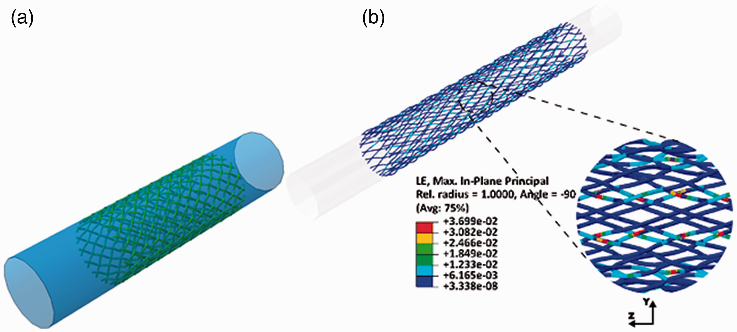
The results of the braided structures under crimping in the form of deformation contour plots is shown in Figure 7 for the biaxial braided structure, and Figure 8 for the triaxial braided structure. The deformed configurations contour plots for the biaxial braided structure (Figure 7(b)), portray a peak deformation of 3.69% after 50% crimping of the structure, while the contour plots for the triaxial braided structure (Figure 8(b)), indicate a peak deformation of 3.79% after 50% crimping of the structure. The results from the contour plots illustrate that the peak strains mainly appear on axial yarns within the braided structure and less strains on the clockwise and anticlockwise yarns within the structure, which shows that axial yarns can be used to offers additional support to braided structures.
(a) 3 D model of biaxial braided structure inside the crimper prior to radial compression, (b) contour plots for deformed configuration of 16 biaxial braided structure and crimper at D = 0.5 Do.

(a) 3 D model of triaxial braided structure inside the crimper prior to radial compression, (b) contour plots for deformed configuration of triaxial braid and crimper at D = 0.5 Do.
Axial load and stiffness analysis
The axial deformation of a braided structure has been characterized by first a low increase in axial loading (force (Fa) due to axial deformation) under increasing radial compressive deformation, then a near linear increase of the axial load as the braid continues to undergo deformation. It has been established that during this deformation criterion all the biaxial yarns contribute to the stiffness of the braided structure and that yarn properties govern the behaviour of the structure [32]. This explains the results for the axial force and axial stiffness for the braided structures developed in this study. According to the results in Figure 9, the axial force (force (Fa) due to axial deformation) during the crimping of the braided structures increases with decrease in diameter of the structures. The results show that the rate of increment of axial load in triaxial braided structure is higher than that of the biaxial braided fabric, it was also observed that the analytical axial force was lower than the triaxial force. This could be attributed to the fact that yarn deformations in the braided structures increased with the number of axial yarns. Hence, interacting biaxial yarns and axial yarns form a mechanical reinforcement that increases the ability of the braided structure to resist external loading [32,33]. The difference between the analytical model and numerical model could be due to the action of connectors in the numerical model at the intersection between the braided yarns. The connector elements were used to control the translation of the yarns at the crossing points causing a pivot like movement at the intersection. In Figure 10, the stiffness-length results show that the stiffness of braided structures increases with decrease in the diameter of the structures during radial compression of the braided fabrics (crimping). The triaxial braided structure was seen to have the faster rate of increment of stiffness with change in diameter compared to the biaxial braided structures, it was also observed that the analytical longitudinal stiffness (equation 3) was slightly lower than the triaxial longitudinal stiffness. This could be attributed in part to axial yarns affecting the compression resistance of triaxial braided structures; axial yarns are stiffer and resist deformation [33], however the friction at the yarn-yarn interface could also be contributing factor to this scenario. Triaxial braided structures are generally stiffer than conventional (biaxial) braids, which is also portrayed by our data in this section. The difference in stiffness could be attributed to the type of connector element that was chosen to model the contact between two crossing yarns. It was noted that one of the factors influencing the magnitude of the radial forces and the hysteretic behaviour of the braided structure was the friction force between the braided yarns and the crimping tool. In all case scenarios, the higher the friction, the greater the force required for the braided yarns to slide inside the crimper, inducing higher radial forces in the loading phase moreover metallic braided yarns are more susceptible to inter-wire wear due to friction as compared to polymeric braided yarns [34]. Clinically this would enable triaxial braids to offer more support as compared to biaxial braids.

Effect of change in axial force causing elongation of the braided structure (Fa) with final diameter, D (mm) during crimping of biaxial and triaxial braided structures showing analytical model [31] and FEM curves.

Effect of change in longitudinal stiffness, Kl with final diameter, D (mm) during crimping of biaxial and triaxial braided structures showing analytical model [31] and FEM curves.
Mechanical stress analysis
The analysis of stress results, Figure 11, shows that the von Mises stresses increased with a decrease in the braid diameter considered in this study, with the stresses in the triaxial braided fabric having a higher rate of increment than the biaxial braided structure. It was also observed that the analytical von Mises stress was lower than the triaxial von Mises stresses, in essence the triaxial braided structure results show a faster rate of decrease up to 20% of the braid diameter (≈17.6 mm, diameter) then decreases slower than biaxial, but remains above von Mises stress values of the biaxial braid model. Other findings have established that Von Misses stress was influenced by axial yarns in braided structures [33]. In Figure 12, the rate of change of tresca stress with diameter of the braided structure is depicted. It shows that the tresca stress of braided structures increases with decrease in braid diameter during radial compression (crimping). The results further indicate that the curve for triaxial braided structure model decreases faster up to 20% of the braid diameter (≈17.6 mm, diameter) then decreases slower than biaxial, but remains above tresca value for biaxial braided structure, it was also observed that the analytical tresca stress [18] was lower than the triaxial tresca stress from the finite element model. This is attributed to the fact that tresca stress measures the maximum shear stress in the material, in the case of the braided structures considered in this analysis, the crimp at the interface between clockwise yarn and anti-clockwise yarn is a contributing factor in the shear stresses in the braid during radial loading.
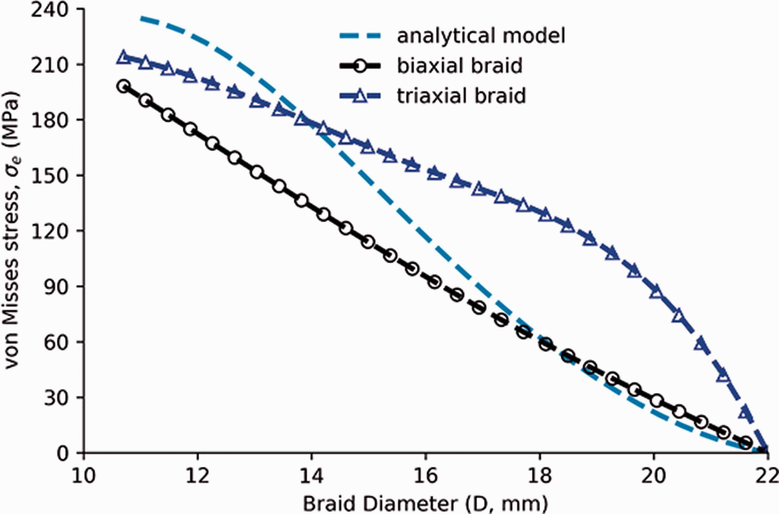
Effect of change in von mises stress (σe) with final diameter, D (mm) during crimping of biaxial and triaxial braided structures showing analytical model [31] and FEM curves.

Effect of change in tresca stress (τe) with final diameter, D (mm) during crimping of biaxial and triaxial braided structures showing analytical model [31] and FEM curves.
Radial pressure and radial force analysis
There has been evidence that as the number of constituent yarns within the braided structure increases, there is likelihood of the resistant force in the structure increasing, due to the fact that the more braided yarns there are, the denser the braided structure becomes [35]. This is consistent with the results of radial pressure and radial force recorded from the braided structures considered in this study. The analysis of radial pressure results shown in Figure 13, indicate that the radial pressure increased with decrease in diameter of the structures. The triaxial braid decrease (up to ≈17.6 mm, diameter) then started decreasing at a slower rate than the biaxial braid model, it was also observed that the analytical radial pressure model [18] was lower than the radial pressure from the finite element model. In terms of the radial force, results in Figure 14 show triaxial braided structure model decreases faster up to 20% of the braid diameter (≈17.6 mm, diameter) then decreases slower than biaxial, but remains above the radial force biaxial value.

Effect of change in radial pressure (PR) with final diameter, D (mm) during crimping of biaxial and triaxial braided structures showing analytical model [31] and FEM curves.
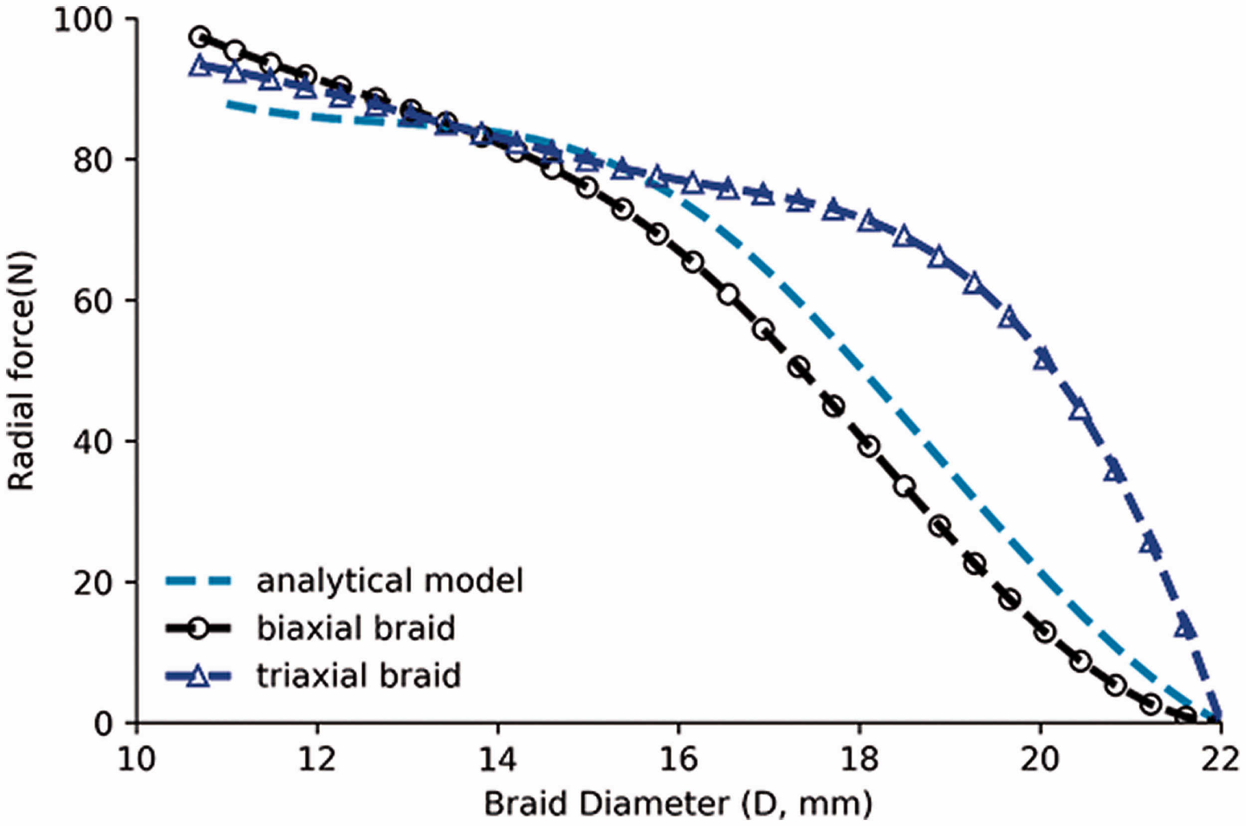
Effect of change in radial force (FR) with final diameter, D (mm) during crimping of biaxial and triaxial braided structures showing analytical model [31] and FEM curves.
Cover factor and braid angle analysis
The cover factor is defined as the ratio of yarn-occupied area within a unit cell to the area of the unit cell [36–38] During deformation of the braided structure as a result of crimping action, constituent yarns within the structure tend to be displaced towards the transverse axis. This leads to yarns getting closer to each other resulting in deposition of the higher number of yarn coils [39]; consequently, the longitudinal length of the braided structure increases to accommodate the transverse displacement of the yarns [5] and reduction of diameter of the structure. This is portrayed by the results in Figure 15. The figure shows that there was a uniform rate of change of the cover factor of braided structures with diameter of the fabrics. The results further illustrate that the triaxial braid diameter decreases by 20% (≈17.6 mm, diameter) after which it decreases slower than biaxial, but remains above biaxial braid values. The results further show that the analytical model initially follows the biaxial curve well, but after 20% compression predicted a higher rate of cover factor with change in diameter. Analytical models of the braided structure [18] also portrayed a profile similar for the biaxial and triaxial braided structures.

Effect of change in cover factor with final diameter, D (mm) during crimping of biaxial and triaxial braided structures showing analytical model [31] and FEM curves.
The difference between the cover factor for the models considered in the analysis, is due to the fact that in the case triaxial braids, the cover factor is influenced by axial yarns. Moreover, the area covered by the axial yarn depends on the position of the individual yarns [37,38].
An increase in braid angle leads to deposition of braiding yarns more towards the transverse axis. This leads to an increase in the length of the braided structure [39] as its diameter D decreases, which explains the profile of the curves plotted in Figure 16; which shows rate of change of braid angle with diameter of the braid. It was established from the results that the braid angle decreased with decrease in diameter during radial compression of the structures (crimping). The results for braided structure in Figure 16 show biaxial braid increases faster in first 20% (≈17.6 mm, diameter) of increase of the braid diameter (D), after which it decreases slower than triaxial, but remains above triaxial braid angle biaxial value. This suggests that the evolution of braid angle during deformation of the structures are similar for triaxial or biaxial braids, implying that the mechanical behaviour is highly dependent on braiding angle [32]. Furthermore, it has been established in past studies that cover factor has a strong influence on the in-plane mechanical properties of triaxial braided structures than in biaxial braided structures [37]. In this case the type of braid has the greatest influence on cover factor. As the triaxial braid has a higher level of undulation due to the additional set of standing yarns, the cover factor decreases as a result of an increased number of gaps [40].

Effect of change in braid angle (α) with final diameter, D (mm) during crimping of biaxial and triaxial braided structures.
Conclusion
The methodology for parametric modeling of the crimping behaviour of triaxial and biaxial braided structures has been developed in this paper. The biaxial braided structure was used as a control model to illustrate that the triaxial braided structure considered in this study had a better performance in terms of stiffness and could withstand more stress configuration before failure as illustrated by the von misses stress configuration, radial pressure and force. The analysis performed and the results obtained could be used in design and optimization of geometrical and material properties of triaxial braided structure as well as in evaluation of their performance at real conditions.
Footnotes
Declaration of conflicting interests
The author(s) declared no potential conflicts of interest with respect to the research, authorship, and/or publication of this article.
Funding
The author(s) received no financial support for the research, authorship, and/or publication of this article.