
Abstract
High modulus/high strength continuous fibres are used extensively for manufacturing textile preforms, as a reinforcement, for composites due to their excellent specific properties. However, their brittle behaviour and tendency to separate easily into individual filaments or bundles can lead to damages during manufacturing processes such as weaving and braiding. Thus, the critical step in the development of an optimal yarn for textile-reinforced composites is to find an optimum twist, which results in a minimum loss of properties of the composite laminates, while maintaining good processability and sufficient strength for textile and/or composite manufacturing. In this study, twist level has been varied to improve the handling and tensile properties of S-glass yarns (i.e. tensile strength). Varying levels of yarn twist (15–40 twists metre−1) were employed to study its impact on the tensile properties (i.e. tensile strength, modulus, elongation at break etc.). Furthermore, the effect of twist on the tensile properties of non-crimp cross-ply composites produced via vacuum infusion process was studied. It was observed that mechanical performance (i.e. tensile strength properties) of twisted yarns is improved up to 30 twists metre−1 while it is deteriorated at 40 twists metre−1. At yarn level, the experimental results were compared with theoretical estimations utilizing existing models for twisted yarns properties. Discrepancies were observed between experimental and theoretical results especially for high level of twist. The tensile strength and elongation of S-glass cross-ply composites at all levels of twist were higher compared to the composite laminates manufactured by using non-twisted yarns. At composite level, the experimental results were also computed employing rule of mixture and good agreement was observed between experimental and predicted results.
Introduction
There is a growing interest in the use of textile structures i.e. woven (2 D and 3 D), braided, knitted and UD/cross-ply preforms as reinforcement for composites due to their higher stiffness and strength in the through-thickness direction and their potential to mitigate delamination initiation [1,2]. In cross-ply preform, fibres or plied yarns are positioned alternately in the 0° and 90°orientations as shown in Figure 1. Such an elaborate configuration of layers is required to endure a more complex stress state [3,4]. Cross-ply composites offer higher resistance to delamination and also present higher compressive strength than woven fabric composites owing to the greatly reduced waviness in the non-crimp cross-ply composites [5].
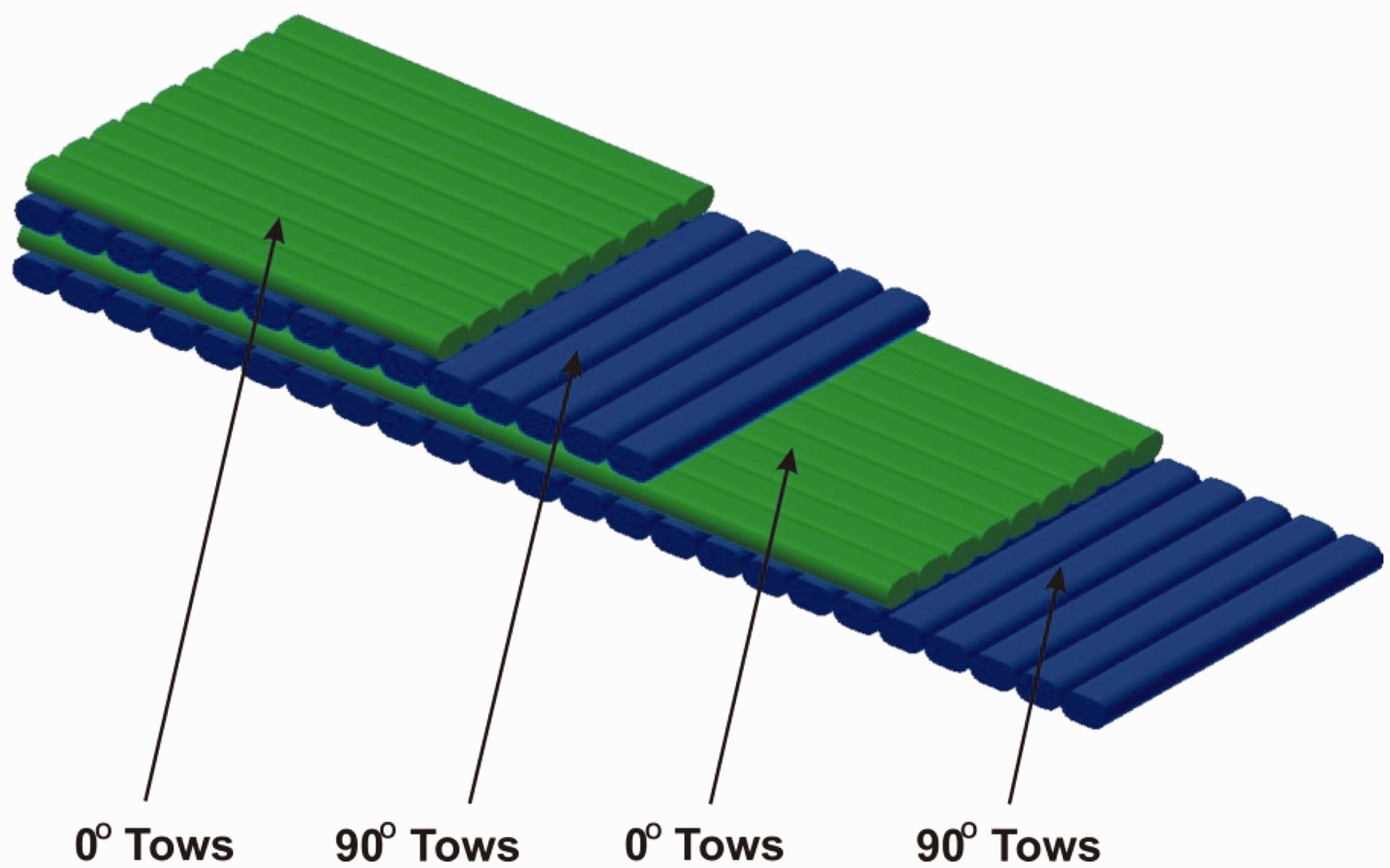
Cross-ply preform structure [4].
Generally, most of the reinforcements for textile composites are made from multifilament yarns with little to no lateral cohesion. These filaments do not possess uniform properties and the strength of the composite is dependent upon the weak spot in the filament i.e. broken filament in strand [6–8]. These assemblies of filaments can separate easily into individual filaments or bundles resulting in damage during manufacturing process [9]. The use of sizing agents is prevalent to enhance the cohesion forces between filaments of brittle strands [10,11]. However, the resulting properties are not still sufficient enough and the processing cost is higher [12]. Twisting is an important process, which induce lateral cohesion between filaments of twisted yarns and improve their processability during preform fabrication [8,13], Twisting also help to localise the micro-damages in the yarn [14,15]. The mechanical properties of yarns (tensile strength and modulus) are also influenced by twisting. In general, the tensile strength and modulus of yarn are increased when the yarn is slightly twisted [16]. However, the strength, stiffness and permeability of yarns can be reduced when higher twist is applied due to the increased difficulties of resin impregnation and fibre obliquity [17–20]. Clearly, the influence of twist can transfer to composite laminates. The tensile strength of high twisted yarn composites is dropped up to 70% when compared to low twist yarn composites [21].
Many inter-dependent structural parameters i.e. single filament diameter
Many researchers have tried to establish relations of the twist angle with modulus. However, these relations are restricted to application to an embedded fabric in a resin system because the fibre deformation in the matrix is considerably smaller [24]. Additionally, Hearle et al [25] and Morton et al [26] found the ideal helix assumption for twisted yarns is not valid for those textile composites with twisted yarns in which the migration and the micro-buckling are formed during the fabrication process. However, some observations suggested that over short lengths of yam, the ideal helical structure appeared to be a good approximation to reality. Researchers [27–30] have suggested an analytical model for twisted impregnated yarns considering the micro-buckling, migration and twist angle of twisted yarns. Further, Naik et al. [31] concluded that the transverse tensile strength of the impregnated twisted yarns has been improved compared to with those of the corresponding impregnated strands.
Several researchers have studied the effect of twist on mechanical performance of yarns, textile reinforced composites [32–34], and their findings have illustrated that sufficient mechanical performance of yarns (i.e. tensile strength) can be achieved via applying a certain twist to these yarns. The S-glass yarns have high strength and modulus and are an ideal candidate for aerospace applications [35,36]. Extensive research work has been published on mechanical properties of textile composites manufactured by incorporating S-glass yarns [37–39]. But literature on effect of twist on tensile properties (i.e. longitudinal tensile strength) of S-glass yarn and subsequently on composites manufactured by this high strength yarn is scant. As already mentioned, twist level not only facilitate the textile reinforcement manufacturing process by making the yarn uniform but also enhance the mechanical strength of yarn and composites when optimum twist is applied. However, the tensile properties of yarns are generally deteriorated beyond an optimum level of twist. So in the present work, S-glass yarns were manufactured with varying twist levels and subsequently cross-ply composites from these yarns. The effect of varying twist at multi-scale i.e. on properties of yarns (strength, modulus, and breaking extension of the yarns) and composite (strength, modulus and strain to failure) was studied to identify the optimum twist levels for enhanced mechanical performance. Theoretical estimations of strength have also been made by utilizing existing yarn models and rule of mixture at yarn and composite levels respectively.
Experimental work
Materials and yarns preparation
In this study, S-glass yarn, which has linear density 33 tex (g/km), supplied by AGY industries was used to produce the twisted S-glass yarn combined from 18 individual yarns. Yarn specifications are given in Table 1. In order to manufacture these yarns, a novel variation of the setup of the twisting machinery has been developed and used to introduce a variety of twisting angles into yarns. A schematic diagram showing this setup is illustrated in Figure 2.
The properties of the S-glass yarn.


Schematic of twisting process.
The untwisted glass yarns with approximately 624 tex linear density (i.e. 18 S-glass yarns), are supplied from yarn packages which are mounted on the holder in conjunction with an electric motor (Part A in Figure 2), pass through a tensioner (Part B in Figure 2). The tensioner is used to optimize the yarn tension and prevent entanglement of the filaments. The holder, which is connected directly with electric motor (Part A in Figure 2), is rotated in clockwise direction at an appropriate speed to provide the required twist on the yarns axis. Once the yarns emerge from the tensioner, they are passed through profiled driven rollers (Part C in Figure 2), which supply and control the linear velocity of the yarns along the machine. When the first rotation is applied to the yarns, the twist insertion actually happened and filaments deformed in a helical form, and each additional rotation increased the number of turns of twist and twist angle respectively. Then, the twisted yarns are wound with a constant tension onto a package that is placed on a yarn winder in a warping unit to avoid entanglement. Thus, the general formula for the suitable twist which can impart to filaments is given by equation (1) [40]


Geometry of twisted yarns and twist angle (a), and cross-section of twisted yarns (b).
In this study, six types of yarns are made with twisting levels ranging from 15 to 40 T/m and these yarns are used to weave non-crimp cross-ply preform (Figure 4) using robotic tow placement machine with 8 yarns per cm in both warp and weft directions.

Image of Cross-ply preform, TexGen software image (a), scanned preform image (b).
In this study, a Z- direction of twist has been selected. While twisting levels 15 and 20 turn per meter (T/m) are classified as low twist (LT), twisting levels 25 and 30 T/m are classified as medium twist (MT) and twisting levels 35 and 40 T/m are classified as high twist (HT).
Fabrication of composite samples
Composite laminates were manufactured using non-crimp cross-ply preform. In order to manufacture these laminates, [0, 90]4 layups were used resulting into 8 plies of cross-ply structure as can be seen in Figure 5. Vacuum assisted resin infusion method was adopted to manufacture these composites. Epoxy resin with a low viscosity Araldite LY 564 and hardener Ardur 2954 with a ratio of 100:35 by weigh were mixed and degassed before infusion. The recommend cure cycle of 120 minutes at 80°C followed by 8 hours at 140°C was adopted. After curing, the composite laminate panels were machined with aiding water-jet diamond cutter to produce the test specimens of required dimensions.

Image of 8 layer cross-ply composite, ideal geometry created by Texgen (a) and a cross-section used in present study (b).
Seven types of composite samples were made and their specification are presented in Table 3. The density and volume fractions of composite laminates were measured by using the immersion and burning methods according to BS EN ISO 1183-1 and BS EN ISO 1172 standards, respectively. It is interesting to note that the volume fraction of S-glass fibre composites increased with increasing twisting levels and this because of the increasing of yarn packing fraction of the yarns [43].
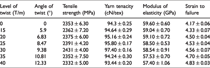
Tensile strength properties of S-glass yarns at different levels of twist.
Models of twisted yarns
The theoretical modeling of yarn properties can be a useful tool to prepare right-first-time yarns for the intended application. In an industrial setting, new types of yarns can be developed more quickly using models by adjusting the design of a yarn already in production or designing a completely new yarn. So that, the risk, time and designing costs of a yarn can be reduced significantly by modelling prior to yarn production [44], The main properties, which are influenced by the addition of twist to a yarn under loading, are the stiffness and strength of this yarn. This is because of the orientation of individual filaments increase in eccentricity to the longitudinal direction with increasing twist level. Thus, a loss of longitudinal stiffness occur due to this off-axis eccentricity. One of the earliest model, which took into consideration the changes in fibre orientation as main reason for variation of yarns properties, is known as either 

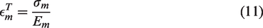
The yarn strain can also be varied by changing the twisting levels or varying the path of filaments in yarn along the yarn axis. By considering the Poisson’s effect, the strain on the yarn can be modified from Hearl’s equation [6] and the strain to failure of twisted yarns can be determined from following equation [46]
Mechanical testing
To elucidate the effect of twist on the mechanical properties of the yarns i.e. tensile strength, modulus of elasticity and elongation, tests were conducted following ASTM D2256-2, with a gauge length of 250 mm and a rate of 0.2 mm/s on the yarns (Instron 4411, n = 10). Optical microscope was used to measure the diameters of twisted yarns. The diameter of yarn was not perfectly round and the change in the yarn diameter along the yarn axis was small at the same twisting level, so that, the mean values were adopted as the diameter of the twisted yarns in this study. The yarn twist angles were estimated employing image processing software, ImageJ. The linear density of twisted yarns was obtained by weighting 500 mm of the twisted yarns on Mettlo Toledo analytical semi microbalance machine. The tensile strength of the un-twisted and twisted yarns was measured by dividing the breaking force over the cross-sectional area of the yarns. In addition, the elastic modulus of the yarns was calculated from the slope of the linear region of the stress-strain curves. Meanwhile, the toughness of yarns was determined by integrating the area under the stress-strain curve.
To characterize the effect of twisted yarns on the mechanical properties of composite laminates, tensile strength tests were performed in accordance with ASTM D3039M 2008 (250 mm × 25 mm rectangular samples were tested displacement rate of 2.0 mm/min using Instron testing machine 5982). (Instron 5982, n = 5). The strains were recorded along the specimen length and width directions using a video extensometer monitoring a gauge length of 50 mm.
Results and discussion
Effect of twist variation on mechanical properties of yarn
The effect of level of twist on the mechanical properties of yarn is characterized using twist or helix angle made by the fibre bundle with respect to yarn axil direction or by the measurement of changes in the diameter of yarn. The twist direction denoted by the letter ‘’S’’ or ‘’Z’’, which represents the orientation of the filaments on the surface of the yarn with respect to the yarn when placed in a vertical position.
Figure 6 shows the optical microscopy images of glass yarns that are subjected to range of twisting levels from 15 to 40 Turn per meter to induce varying twist angles. Ideally yarn cross-sections should be measured to capture the changes in yarn cross-sectional area which in turn can also give idea about yarn packing fraction and intra-tow voids for resin flow. As this is not focus of the present study, so only yarn diameters from microscopic images are calculated to estimate the change in diameters of yarns with varying twist levels. In future study, we plan to measure the yarn cross-sectional areas at each twist level, which will help to study the change in yarn packing fraction and intra-tow voids for resin flow. Coming to Figure 6, it is observed that the fibre-twisting angle (θ) increase with increase in number of twisting level (T), while there is a decrease in the yarn diameter (d). As an example, 15 T/m corresponds to a fibre twisting angle of 5.90° and equivalent diameter of yarn 1.043 mm, while 40 T/m corresponds to θ = 12.23° and d = 0.67 mm. and that is because of filaments inside the yarns become more tightly configured with increasing twisting level.

Optical images of glass yarns at various twist levels.
Figure 7 and Table 2 present the strength properties of glass yarn at various twist levels. Figure 7(a) shows the tensile strength - strain plots for twisted glass yarns. Specifically, the low twisting levels (i.e. 15 and 20 T/m) results in small increase in the tensile strength of twisted yarns compared to non-twisted yarns. Then, with increasing twist levels up to 30 T/m, the maximum tensile strength of twisted yarns is achieved. However, beyond this twisting level, additional twist has been illustrated to reduce twisted yarn strength. The small increase of tensile strength at lower twisting levels can be attributed to the orientation of the filaments in straight path as most of filaments are oriented in a straight path with the longitudinal axis of the yarn producing low interfacial contact and these straight yarns fail under shear amount of slippage. On further twist increase, the inter-friction of filaments increase leading to higher yarn packing density. The increase of packing density means that more filaments are connecting together along the yarn direction improving their resistance to slippage through friction. Moreover, with increasing twist to high levels (i.e. 35 and 40 T/m), the binding of filaments continue until they start to interlock. The interlocking of filaments occur due to converting the tensile stress to transverse stress during the tensile deformation as result of high twist action.

(a) Tensile strength-strain curves for various twist levels, (b) Tensile strength with various twist levels, (c) Modulus of Elasticity for different twist levels, and (d) Strain to failure for various twist levels (±1 SD).
When stress is continuously built up in the twisted yarns under tension, the interlocking of filaments can prevent the inter-fibres shear motion or slippage, and consequently the strength of twisted yarns is improved. Thus, it is noticed that during the tensile loading of the twisted yarns, the apparent stress-strain curves behave as a short linear region because of slippage of filaments inside the yarns followed by nonlinearity with considerable extension while the filaments continue to slip and finally failure occur.
As noticed in Figure 7(a) and (b), the tensile strength of glass yarns increase at medium twisting levels (i.e. 25 and 30 T/m), which is considered optimum level. Beyond this levels, the filaments are oriented far away from the yarn axis making the contribution of filaments strength to the glass yarns strength less effective and hence reduce the overall yarn strength. Hence two phenomenon are observed here. First, the increase in strength with twist is associated with increase in cohesion of filaments under twist, while the second is decrease of strength with twist, which is associated with filaments obliquity under high twist leading to reduction of the contribution of filaments strength to that of yarns. These behaviours are in agreement with the conventional understanding of relationship between strength and twist in the textile yarns [46,47]. The relation between the stiffness (i.e. Young modulus) of yarns and twisting levels are also shown in Figure 7(c). As can be seen, the Young modulus values for six types of twisted yarns are generally lower than the Young modulus of the non-twisted yarns; they varied between (59 GPa and 57 GPa), while the value of 59.60 GPa is found for the non-twisted glass yarns. The reduction in the Young’s modulus of twisted yarns at lower twisting levels can be attributed to the twist contraction. The length of most filaments is longer than the length of yarn due to helical structure of the yarn. Consequently, as the load direction and the filament orientation are not the same, the filament strength is not fully translated to the strength of the yarn and results in the comparatively low modulus of twisted yarns compared to the non-twisted yarns [16,48].
Elongation and strain to failure of yarns-twist relation are presented in Figure 7(d). It is observed that the elongation of the yarns increased with increasing twist levels. The strain of the yarns strongly depends on the strain of the individual filaments, which can sustain while they are subjected to tensile loading. So that, the twisted filaments have extra length between jaws and are stretched more compared to untwisted filaments and the tension load become more concentrated towards the yarns core. This extension in the filaments increase their lateral pressure and compaction, resultantly yarns become more dense and coherent to strain. Thus, at low twisting levels, the individual filaments can intercept higher loads leading to slight improvement in the elongation compared to untwisted ones. On increase of twist levels, higher elongation has been achieved as the coherent forces in the yarns stop the filaments from absorbing all the tension load consequently avoiding early breakage.
The relation of toughness with yarn twist is presented in Figure 8. The toughness value are measured from integrated area under stress-strain curves. It can be seen from Figure 8 that unlike strength measurements, the high value of toughness (

Toughness of yarns at various levels of twisting.
The obtained experimental results of yarn mechanical properties are also compared with theoretical estimations from existing models of yarn to verify the validity of these models. Thus, the tensile strength, modulus of elasticity, and strain to failure for all twisted yarns obtained experimentally at various twisting levels (15 - 40 T/m) are plotted against the theoretical results, which are extracted from the equations (4) to (6) for verification. The values of

Comparison of predicted and experimental of a) Tensile strength, b) Modulus of Elasticity and, c) Strain to failure for twisted yarns at various twist levels.
Unlike the tensile strength results, the model over-predicts the modulus of elasticity (Figure 9(b)). Additionally, the difference between model values and experimental observations is smaller than 10% for all levels of twist, which implies that the theoretical model can predict a relatively accurate value of the modulus of elasticity.
The elongation behavior of twisted S-glass yarns in both experimental and theoretical observation are also shown in Figure 9(c). The range of experimental data generally lied with range of model at low and medium levels of twist but there is difference in values at high levels of twist which could be due to the model equation doesn’t take into account the fibre length and their migration with increasing of twisting levels.
Composite mechanical properties
The specification of composite laminates, which made from the S-glass composites at different levels of twist, is illustrated in Table 3. Further, the mechanical behaviour of representative S-glass composites at different levels of twist is presented in Table 4 and Figure 10. It can be noticed from the composite stress-strain curves in Figure 10(a) that for all twist levels, composite samples appeared a non-linear stress-strain response which is typically associated with the cross-ply composite structures [49]. In cross-ply laminates, 0° plies are loaded along the reinforcement fibres while 90° plies are loaded in transverse direction. Polymer matrix is weakest in the composite and on application of load, the matrix cracking of 90° plies starts followed by transverse ply failure in the early stages, which can be noticed as non-linear behaviour of stress-strain curves. On application of further load, the 0° plies start cracking laterally and finally these plies fail due to fibre breakage. The fibre breakage of 0° plies can be seen in Figure 13. Interestingly, increasing twisting levels exaggerates the non-linear stress-strain response. This behaviour can be attributed to the addition of twisting of the S-glass yarns due to which most filaments are helically wound around the axis of the yarns [50].
Specifications of composite laminates.

Tensile strength properties of composite laminates at different level of Twist.


Effect of twist on the (a) Tensile strength-strain plots and (b) Tensile strength, (c) Modulus of Elasticity, and (d) Strain to Failure verse twisting level of composites.
Hence, most of filaments are not completely aligned but rather are off-axis to the yarns direction. It is expected that this additional non-linear elastic response could be due to the rotation of these filaments upon load application and subsequent stretching of rotating filaments. Thus, uncoiling and reorientation of filaments in the twisted yarns during tensile loading [29] can also be reason for the non-linear stress-strain behaviour in the twisted S-glass composites. It is found from the results of Hao Ma et al. [51] reported that increase in twist level of sisal composites can increase the displacement of failure.
The tensile strength of glass yarns composites at different twist levels are presented in Figure 10(b). It can be observed that with increase in twist of the yarns up to 30 T/m, the tensile strength of composite increases and then there is slight decrease in strength on application of further twist. The higher strength at 30 T/m can be attributed to the better interfacial adhesion of twisted filament and epoxy, which provide better lateral cohesion between filaments and the bonding shear strength between the filaments and epoxy, respectively. Similar behaviour has been reported in the literature [8,52]. The decrease in the strength of composites with higher twist levels may be attributed to the obliquity of the filaments and inability of resin infiltration in highly twisted yarn due to decrease in the cross-sectional area of twisted tows resulting in low inter-filament gaps [51]. From the stress-strain response of composite laminates at the different twist levels, the Young’s modulus is also determined using the initial tangent modulus in the strain range of 0.025 -0.100% (Figure 10(c)). Figure 10(c) clearly shows that the modulus of composites increase up to 25 T/m then there is immediate drop afterwards. This can be attributed to the increase of obliquity, the deviation of the filaments axis from the yarn axis resulting in a number of slack filaments from their position leads to drop of E-modulus. These results confirmed with investigation of Rask et al. [53], which showed that with increasing twisting until an optimum level, the tensile modulus of fibre composite laminates increased. While the tensile modulus of composite laminates started to decrease beyond an optimum level of twist. The strain to failure of composites laminates, which corresponds to the effective strain at tensile failure of yarns is presented in Figure 10(d) and it can be seen that failure strain increase with increasing levels of twist. By the increasing of twisting level, possible micro damages of filaments in the yarns can be localized, leading to possible increase in the failure strength of the yarns and consequently composites. In addition the results of investigation of Cheung et al. [54] showed that the strain to failure for Kevlar 49 twisted tubular braided composites was increase with increasing level of twist. Similar behaviour of increase in failure strain with an increase in twist level has been reported in the literature for sisal fibre composites [51].
In addition, the experimental tensile strength of composite laminates values are compared with theoretical tensile strength values and shown in Figure 11. It can be clearly noticed from Figure 11 that both experimental and modelled values of tensile strength were increased with increasing level of twist up 30 T/m. Beyond the 30 T/m, it can be seen that the model values increased with increasing of level of twist, while the experimental values showed drop off with increasing level of twist. This is possibly because of modelling equations could not catch the damage failures which occurred in the S-glass filaments at high level of twist and thus alternative model with complex equations is required for investigation these behaviour.

Comparison of experimental and predication tensile strength of non-crimp composite laminates ate different level of twist.
The tensile strength of non-crimp cross-ply laminate theoretically comes from the longitudinal and transverse tensile strengths of laminas of this composite as shown in Figure 12.

Configuration of non-crimp composite laminate.
So that, the rule of mixture can be applied to calculate the tensile strength of this composite while both longitudinal and transverse directions are 50% in the [0, 90]4 configuration. The longitudinal tensile strength of the unidirectional lamina is calculated from the following equation [55].
Where,
The transverse strength of unidirectional lamina is also calculated using following equation [55]


In this study, we calculated the theoretical tensile strength of non-crimp cross-ply composite laminates measured from
Mechanical properties of S-glass fibre and epoxy resin.

As can be seen from Figure 11, the theoretical results are capturing the trend very well upto 30 T/m after which there is inconsistency that there is decrease in experimental values while the theoretical values are still showing increasing trend. This can be attributed to the fact that theoretical estimations are based on assumption that no fibre damage occurs in glass yarns and there is perfect interfacial bonding between fibres and epoxy. So we speculate after certain level of twist when there might be some fibre damage, experimental results show decreasing trend while theoretical values keep on increasing because of absence of fibre damage consideration in theoretical estimations. The fracture surface of the tensile test specimen also give insight into the effect of twist on how damage failure occur. It can be seen that for the non-twisted S-glass yarns (Figure 13(a)) a more serrated and uneven fracture occur and the composite failure is fibre controlled. In addition, the fracture path is longer and starts running along the length of filaments. Meanwhile, in the twisted S-glass yarns composite at 30 T/m (Figure 13(b)), the tensile fracture is macroscopically brittle with flat fracture surface and the composite failure seems to be matrix controlled

Fracture of tensile specimens (a) Non-twist S-glass composite (b) Twisted S-glass yarns at 30 T/m.
Conclusion
Optimization of yarns to facilitate the manufacturing process for textile reinforcements and improvement in the mechanical performance of resulting textile-reinforced composites is a key challenge for materials scientists and engineers. The current work aims to balance between processability and the mechanical properties of high–performance fibres (i.e. S-glass yarns) and cross-ply composites.
Introduction of twist to yarns can improve the processability of the yarn but it can also affect the mechanical properties of yarn and resulting composites. Here, in this study, different levels of twist were applied to S-glass yarns and non-crimp cross-ply composites were manufactured with these yarns. Effect of twist was studied on the tensile properties of both yarns and cross-ply composites and an optimum level of twist was studied to enhance the mechanical performance of yarns as well as textile reinforced composites. Existing theoretical models were employed to calculate the tensile properties of the yarn in order to investigate the validity of these models with obtained experimental results. Furthermore, tensile properties of the composites were estimated by utilizing modified rule of mixture for cross-ply composites. Expectedly, the tensile properties (i.e. longitudinal tensile strength) of the twisted S-glass yarn increased with increasing level of twist up to an optimum point before it starts to deteriorate. For instance, the tensile strength of twisted S-glass yarns improved by increasing the level of twist up to 30 T/m. The theoretical models for yarns were able to capture the trend of the modulus of elasticity but there were discrepancies between the experimental and theoretical results for strength and stiffness of twisted glass yarns, especially at higher twist levels.
It was noticed that twist can enhance the mechanical performance of the twisted S-glass yarns composites in term of strength and stiffness to a certain level of twist. However, the degradation in tensile properties started after optimum level of twist.
A modified rule of mixture was also employed to calculate the modulus of cross-ply composites numerically and good agreement was observed between numerical and experimental results.
As observed in this work, an optimum twist can effectively achieve a balance between handling and mechanical performance of high strength fibres. In addition, as a general outlook, the favorable properties such as higher strength and improved toughness for composite laminates can be satisfied by the optimization of the twist levels for glass yarns. In future work, authors will try to improve the theoretical models for better estimation of tensile properties of yarns, which in turn can be utilised for determination of mechanical properties of textile reinforced composites. In future study, we plan to measure the yarn cross-sectional areas at each twist level, which will help to study the change in yarn packing fraction and intra-tow voids for resin flow.
Footnotes
Declaration of conflicting interests
The authors declare no potential conflict of interests with respect to the research, author-ship, and/or publication of this article.
Funding
The author(s) received no financial support for the research, authorship, and/or publication of this article.