
Abstract
3D woven composites are considered as the ideal materials for subsea pressure shells owing to their exhibit excellent out-of-plane properties of delamination resistance and compressive damage resistance, which greatly improves the bearing capacity of the structure. This paper presents the influence of the radius-to-thickness ratio and the initial defects on the 3D woven composite spherical shells subjected to external hydrostatic pressure using the multi-scale finite element and theoretical methods. Two kinds of typical 3D woven structures, curved shallow-crossing linking 2.5D, and straight shallow-crossing linking 2.5D, are selected. The results show that the proposed multi-scale finite element method is capable of accurately predicting the strength and buckling behavior of 3D woven composite spherical shells under external hydrostatic pressure loadings, validated by the comparison of theoretical predictions. Furthermore, the fabric structures, radius-to-thickness ratio, and initial defects affect importantly the mechanical behavior of 3D woven composites pressure shells.
Introduction
Fiber-reinforced composites as structural pressure shells are being used increasingly for the underwater vehicle applications owing to their low weight-displacement ratio and high mechanical performance. In the last few decades, special efforts have been focused on the filament wound and multi-ply laminated composites. However, it has been proven that delaminations are the most frequent causes of failure in laminated structures under hydrostatic pressure [1,2]. Moreover, the presence of delaminations results in a reduction of the buckling strength of the overall structures, causing further final failure. Recently, there has been an interest in utilizing weaving techniques from the textile industry to overcome the problems related to laminated composites [3]. More specifically, 3D woven composites exhibit excelle5nt out-of-plane properties for delamination resistance and compressive damage resistance [4]. The complexity of structure makes predicting structural damage more challenging, Guo J H et al. [5] proposed a triple-cell model (TCM) system based on progressive damage method, which can predict the stiffness, strength and damage behavior of 3D woven structures well, and the triple-cell model gives a lot of inspiration to the work of this article. However, the failure of 3D woven composites under hydrostatic pressure is less studied. Consequently, an improved understanding of the mechanical behavior and buckling characterizations of 3D woven composites subjected to hydrostatic pressure will be helpful for researchers in designing and constructing high-performance materials.
As for the underwater pressure shells, the strength and buckling of fiber-reinforced composites are two important design factors [6–8]. In the past few years, several analytical and numerical papers are available. For example, Tafreshi [9] carried out a series of finite element analyses on the delamination buckling and post-buckling of composite cylindrical shells, varying the material properties, stacking sequence, and delamination length, subjected to combined axial compression and pressure. Hur et al. [10] developed a nonlinear finite element program to investigated the post-buckling behavior and progressive failure of composite cylinders subjected to external hydrostatic pressure using the finite element method. Ross et al. [11] concentrated on fiber-reinforced plastic tubes with a mixture of three carbon and two E-glass fiber layers and discussed the collapse responses of circular cylindrical composite tubes under external hydrostatic pressure. Lopatin AV et al. [12,13] developed an approximate analytical model to analyze the buckling problem of the composite sandwich cylindrical shell. Moon et al. [14] evaluated the buckling and failure characteristics of moderately thick-walled carbon/epoxy composite cylinders under external hydrostatic pressure by using the finite element method. They concluded that the initial buckling damage leads directly to the final collapse. Recently, Blachut J [15] studied the buckling behavior of composite domes with localized imperfections subjected to external pressure. Almeida et al. [1] proposed a damage model to calculate the progressive failure of carbon/epoxy filament wound composite tubes under external pressure by using the arc length method. Numerical results indicated that the tubes with a radius-to-thickness ratio lower than 10:1 (thin-walled shells) are mainly governed by buckling, whereas the ones with a radius-to-thickness ratio than 10:1 (thick-walled shells) are dominated by the in-plane shear with delaminations. Pavlopoulou et al. [2] investigated the hydrostatic buckling and crushing behavior of composites cylindrical shells with different structures, pre-preg, filament wound and braided, and reported that as compared to the pre-preg laminated tubes, the braided and filament wound tubes can potentially exhibit higher resistance to external hydrostatic pressure. Lopatin et al. [16] found an analytical solution of the buckling problem formulated for a composite cylindrical shell subjected to hydrostatic pressure. Nicholas et al.[17] used concentric circular carbon fiber/epoxy double cylinder with PVC foam core to study the buckling initiation and overall failure behavior of the test piece under the critical hydrostatic pressure, subcritical hydrostatic pressure, and impact load. Amir et al. [18] optimized the strength and buckling stability of elliptical composite deep-submerged pressure shells using two different filament winding patterns, namely geodesic and planar. Wan et al. [19] studied the characteristic response and pressure performance of sandwich tubes with fiber-reinforced cementitious composite core structure under external hydrostatic pressure.
From the above review of the previous studies, it is clear that thin-walled composite shells fail due to global/local buckling, whereas, for thick-walled ones, materials strength and structural buckling restrict mutually. Moreover, the accurate predictions of failure behavior of textile composite shells are quite difficult owing to the complicated structures. Therefore, the progressive failure process of textile composite shells under external hydrostatic pressure is still unclear. Also, the strength and buckling analysis of 3D woven composite shells subjected to hydrostatic pressure is rarely discussed.
This paper is motivated by assessing the strength and buckling behavior of 3D woven composites by using multi-scale strategy to improve the reliability and stability for a better application. The detailed outline of the work is as follows. First, multi-scale analytical methods are proposed in the next section 2. Subsequently, the strength and buckling theory of pressure shells are presented. Then, the theoretical and numerical results and corresponding discussion are shown in the penultimate section. In the final section, some valuable conclusions are summarized.
Multi-scale analytical method
Because of the complex structure of 3D woven materials, the single scale simulation method has been unable to meet the needs. The internal structure of these materials dominates local stress concentration, damage initiation, and damage progression [20]. So it is very important to adopt multi-scale analysis method [21]. Figure 1 schematically presents the framework of a multi-scale analytical procedure. First, the effective mechanical properties of the matrix-impregnated fiber bundles (micro-scale RVC), which was composed of fiber bundles and matrix, needed to be calculated through experimental data and empirical formulas. Next, the micro-scale effective mechanical properties were entered into the meso-scale RVC model, and the elastic constants and strength values of meso-scale RVCs can be simulated by applying the periodic boundary condition. Finally, the meso-level data were delivered to a macro-scale homogeneous composite component, and then the macroscopic stress response and buckling behavior were calculated. The proposed model was implemented in the finite-element software ABAQUS.

Framework of multi-scale analytical method.
Properties of matrix-impregnated fiber bundles (micro-scale)
In this paper, yarn is quartz fiber bundles, and the matrix is epoxy resin (TDE 86). The mechanical properties of the constituent materials are summarized in Table 1.
Parameters of mechanical properties of component materials.
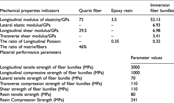
For 3D woven structures, both warp and weft yarns are considered as the matrix-impregnated fiber bundles, which is usually assumed to be isotropic. According to the reference [22], the elastic constants and strength values of the matrix-impregnated fiber bundles are summarized in Table 1, which are used to predict the damage initiation/evolution of the meso-scale finite element model in the subsequent sections.
RVC of 3D woven composites (meso-scale)
Geometrical modeling of RVC
Meso-scale RVC as a bridge linking the micro-scale analysis and macro-scale analysis is critical for the overall multi-scale procedure [23]. 2.5D reinforcements, which are one kind of the special 3D woven structures, can derive rich structural system by changing the configuration of warp/weft. In this paper, the weave styles considered are the typical two types: curved shallow-crossing linking 2.5D structure (AIW-1) and straight shallow-crossing linking 2.5D (AIW-2) as shown in Figure 2. The architecture of the undeformed 2.5D woven composites are periodical in warp, weft and thickness directions. Thus, the Representative Volume Cell (RVC) is picked and marked with red box in Figure 2, as well as its basic dimensions:
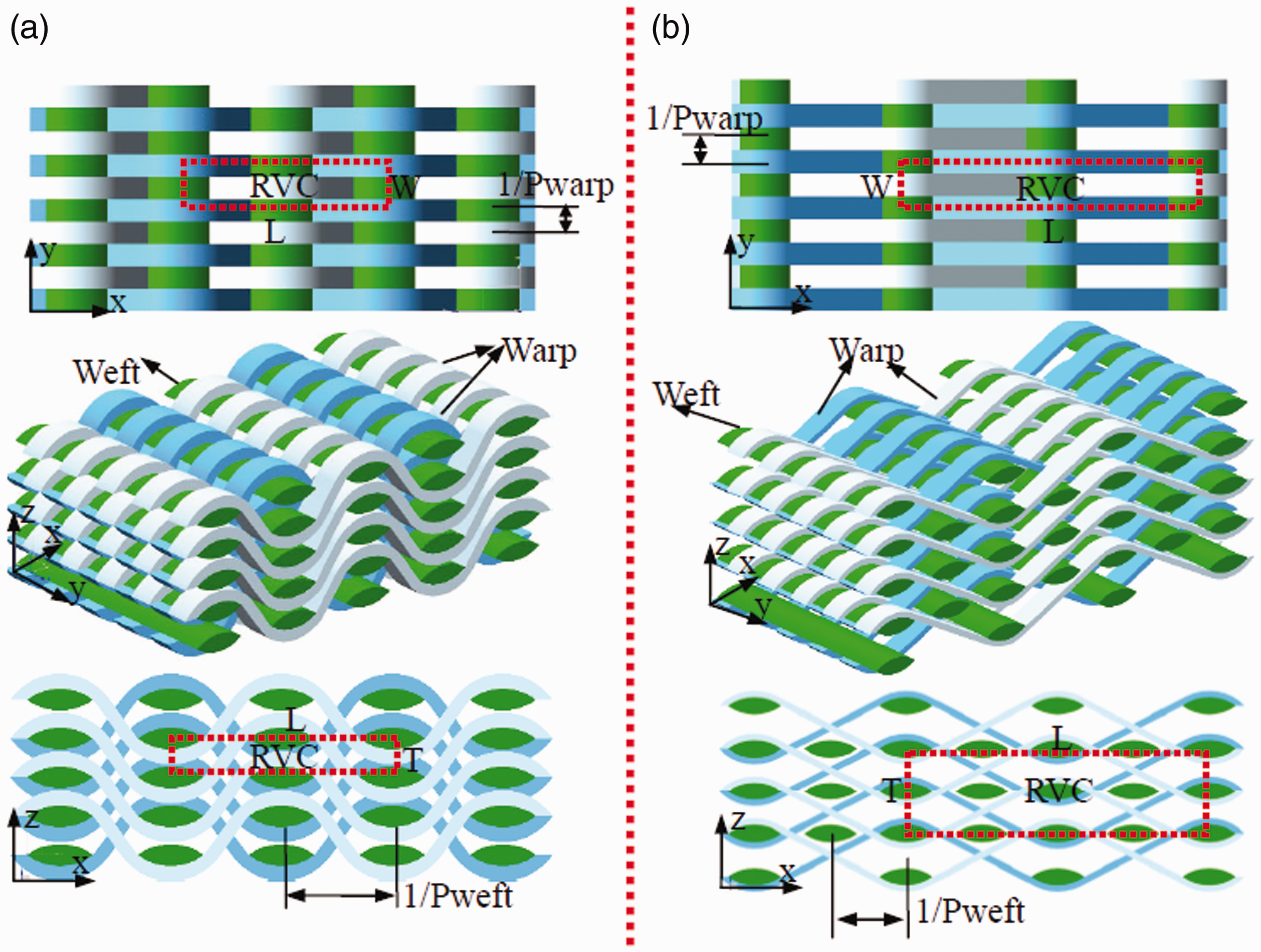
Two types of the weave styles.
The geometry sizes of the solid RVCs.

Based on the microscopic image analysis (Figure 3), the following assumptions should be provided. Warp is divided into two parts. One is curve segment which keeps intimate contact with weft, while the other is line segment. The section of weft yarn is convex lens, while the section of warp is rectangular. The cross sections are considered constant shape along yarns. Weft is straighten.

The microscopic image.
Details of the geometric relationships related to RVC model and their mathematical formulations are given in Ref. [24]. By calculating, the geometry sizes of the solid RVCs are listed in Table 2. Figure 4 shows the meso-scale geometric models.

The meso-scale geometric models. (a) AIW-1 and (b) AIW-2.
Meso-scale voxel-based finite element model and periodic boundary
Meso-scale voxel-based method, which divides meso-scale RVC into a lot of regular hexahedral meshes, is proposed to investigate the mechanical behavior. In this paper, the software TexGen 3.8.2 is carried out to generate voxel meshes. In our previous studies, the results indicate that the voxel mesh size has a minor influence on the mechanical properties as long as the fiber volume fraction of 2.5D woven composites is correctly guaranteed. Here, the mesh size is 0.1 mm × 0.1 mm × 0.06 mm.
As described in Ref. [25], RVC is not isolated from its adjacent RVCs in the composites, and the boundary effects from the adjacent RVCs should be taken into account. Thus, the applied periodic boundary conditions in the present work are to ensure the continuity of displacements on the opposite faces of RVC. Unlike consistent mesh, one obvious advantage of voxel-based model is that applying the periodic boundary conditions is more straight forward and easy. The detailed constraint equations of RVC are described in Refs. [22,26,27].
Damage model
Damage initiation criteria
In this paper, 3D Hashin and maximum stress criterions are formed to define the initial damage of the yarns and the matrix, respectively. Usually, the failure modes of the yarns mainly include the longitudinal tensile/compression failure (L direction), transverse tensile/compression failure (T, Z direction) and shear failure (LT, LZ and TZ direction). Thus, the corresponding initiation criterion under different damage modes can be expressed as follows:
Yarn tensile failure in the longitudinal direction:
Yarn compression failure the longitudinal direction:
Yarn tensile and shear failure in the transverse direction:
Yarn compression and shear failure in the transverse direction: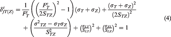
In the above equations,
Matrix tensile failure criterion:
Matrix compression failure criterion:
Damage constitution law
Generally, after reaching the yarn or matrix initial damage initiation, the composites will enter the progressive damage process. This importantly depends on the damage evolution law, which associates with the material fracture density, element strain, element characteristic length. The damage evolution law can be expressed as
Here, dI(L,T,Z) is the damage variables for yarns and matrix. The corresponding equivalent displacement and stress (see Table 2) are employed to describe each damage mode. Also, in the equation (7),
Moreover, based on the continuum damage mechanics, the Murakami-Ohno damage model is used. By definition, the constitution relationship between the effective stress σ* and the undamaged stress 

For yarn at the longitudinal and transverse direction:
For matrix:
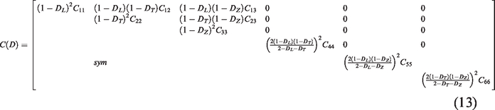
Based on the Cordebos-Sodprpff energy assumptions [28], the damage variable are introduced into the undamaged stiffness matrix, as follows:
Simulation process
After generating the meso-scale voxel-based finite element models, ABAQUS/Standard is employed to simulate the elastic and strength behavior of 2.5D woven composites. In order to implement the above damage model, a user-defined material subroutine (UMAT) is incorporated in ABAQUS. Also, three state damage variables (SDVs), including SDV1 (L directional damage), SDV2 (T directional damage) and SDV3 (Z directional damage), are set in UMAT to analyze the progressive damage process. Here, it should be stressed that the SDVs are evolved from 0 (un-damage) to 1 (full-damage) irreversibly, and the state damage variables are controlled by the damage equivalent strains.
By calculating, the predicted elastic constants and strength values of meso-scale RVC are summarized in Table 3, which are used to simulate the mechanical properties of macro-scale spherical shells in the subsequent sections.
The predicted elastic constants and strength values of meso-scale RVC.

Finite element model of 3D woven composite spherical pressure shells (macro-scale)
The main purpose of finite element analysis is to examine the effect of fabric structure and radius-to-thickness ratio (

The boundary conditions of the spherical hull models.
In order to predict the nonlinear buckling with geometrical imperfections, linear elastic buckling analysis is studied, and the first three order linear buckling instability modes are obtained. Then these modes are set to the initial defect. Both included are analyzed.
Strength and buckling theory
In the classical forth strength theory, the elastic limit pressure is given by:
Or, according to Yu’s strength theory,
Here, as the tensile strength ratio increases, the ultimate elastic pressure decreases and the minimum wall thickness increases. However, the ultimate elastic pressure and minimum wall thickness of the spherical shell are independent of the intermediate principal stress coefficient. Classically, when the shell is subject to a external pressure, the elastic limit pressure of the perfect shell can be given by [30,31]:
Results and discussion
Strength behavior
As shown in Table 4, from both the theoretical model and the finite element model, it can be seen that, with the decrease of the
Finite element analysis failure strength and theoretical failure strength.

By combining the finite element model with the theoretical analysis, we can get a clearer contrast. As for the stress analysis, Figure 6 shows that the element stress on the equator is equal to the theoretical value of the spherical shell, indicating the accuracy of the calculation. For the AIW-1 structure, the element stress in the equatorial region reflects the stress concentration, which may be due to the anisotropy of the material. As the

Stress clouds in structures subjected to external pressure: (a) AIW-1 structure; (b) AIW-2 structure.
Linear-elastic buckling analysis
Linear buckling is based on a linear elastic theory which is under small displacement and strain. The change of structure configuration during load-deformation is not considered in the analysis, that is, the equilibrium equation is always established on the initial structure of the whole structure at every stage applied by external force.
For studying the linear buckling load of the spherical shell and its corresponding modes, the linear buckling analysis of the spherical shell is carried out in Figure 7. The results indicate that the linear buckling modes of all-spherical shells are similar, showing several circumferential and meridional half-wave forms. This buckling mode is in line with the typical spherical shell buckling mode. There is a relationship between

Buckling modes of spherical shells of two materials structure.
For the spherical shells of the AIW-1 structure with five different thicknesses, the first order linear buckling eigenvalues of spherical shells are 4.2749 MPa, 6.6456 MPa, 12.88 MPa, 25.866 MPa and 36.847 MPa, respectively. For the spherical shells of AIW-2 structure with five different thicknesses, the first order linear buckling eigenvalues of spherical shells are 3.7317 MPa, 5.7932 MPa, 11.228 MPa, 22.523 MPa and 32.037 MPa, respectively. The buckling loads and ultimate bearing capacity of spherical shells made from AIW-2 are much less than AIW-1, due to different modulus in both directions.
Non-linear buckling characteristics
The linear buckling analysis cannot solve the instability load of the shell accurately, because the material nonlinearity and initial geometric defects are not considered. To analyze the failure form of the shell more accurately and solve the final instability load of the shell, the nonlinear buckling study of the shell where the above-mentioned defects are considered is carried out. In the nonlinear analysis, the first-mode obtained from the corresponding linear analysis is introduced as the initial geometric imperfection with a magnitude of 5 mm (0.5%).
The paths are shown in Figure 8 showing the relation between the applied pressure and the shell thicknesses. And the paths are similar. The load-bearing increases monotonously to the peak point first, which is the critical buckling load, then it shows a marked downward trend in pressure. As can be seen, the peak point corresponding to the post-buckling mode is also listed. The spherical shell buckling loads of the AIW-1 structure are higher than that of the AIW-2 structure, which is linked to the material strength and modulus. The results can be explained by the greater modulus in the weft direction, the greater tensile and compressive strength in the weft direction. When the spherical shell is under water pressure, these well bear external pressure.

equilibrium path and failure mode of the spherical shells: (a) AIW-1 structure; (b) AIW-2 structure.
It is evident that the nonlinear post-buckling modes at the end of the path take the form of a local dimple. The first yield load of the defective spherical compressive shell is also less than the critical buckling load, indicating that all spherical shells have buckled in the elastoplastic range. From the nonlinear instability mode, with the increasing of proportion, the local collapse site shows a trend in growth around the equator. Combined with linear buckling and nonlinear buckling analysis, it can be seen that the
Where
As can be seen from in Figure 9(a), with the increasing of thickness-to-radius ratio (

The critical buckling pressure (a) and reduction rate of buckling load (b) corresponding to t/R value.
According to Figure 9(b), the reduction rate of buckling load increases first and then decreases while the
Conclusions
In this paper, spherical pressure shells of two materials were analyzed by using multi-scale strength and buckling analysis and the following conclusions are reached: When comparing the merits and drawbacks of these two analysis methods and considering the material nonlinear buckling analysis, geometrical nonlinearity and the initial defects, nonlinear buckling analysis results are more precise than linear buckling analysis. The initial defect has a great influence on the spherical shell, and it cannot be ignored in the actual design of the composites pressure structure. At present, only numerical calculation has been carried out, and no experimental comparison has been given. In the future, the experimental processing of braided spherical shell will be provided to verify the reliability of the model. The research in this stage is based on the numerical simulation results of selected geometric braided structures, fiber materials, and initial defects. Therefore, more in-depth and extensive research is needed to obtain comprehensive images and failure analysis of buckling properties with different fiber materials, different braided structures, perfect and imperfect spheres under external pressure.
Footnotes
Declaration of conflicting interests
The author(s) declared no potential conflicts of interest with respect to the research, authorship, and/or publication of this article.
Funding
The author(s) disclosed receipt of the following financial support for the research, authorship, and/or publication of this article: This work was supported by the Natural Science Foundation of China [grant number 11702115, 12072131]; the Natural Science Foundation of Jiangsu Province (P.R.China) [grant number BK20170166]; the National science and Technology Major Project [grant number 2017-VI-0007-0076]; Key Research Projects of China [grant number 2016YFC0304301]; and Shanghai Aerospace Science and Technology Innovation Fund [grant number SAST-2019105].