
Abstract
The high-quality standards of bodily absorbent hygiene products require that the adhesive bond between layers be as uniform and consistent as possible. The final adhesive pattern of the product is determined by the dynamics of the adhesive fibre, which in turn depends on the nozzle geometry and on its operating conditions. In order to gain a better understanding of the dynamics of adhesive fibres and the deposited application pattern, an experimental study was conducted on two multi-hole melt blowing (MB) nozzles designed for producing hot-melt adhesives. To this end, the fibre dynamics were captured through the use of high-speed imaging (HSI). The main parameters that govern the fibre dynamics, including its frequency of oscillation, were quantified through use of image analysis. The effect of the operating conditions on the fibre’s frequency of oscillation at the nozzle exit region was studied and the results indicate that increasing air-polymer flux ratios
Introduction
In the melt blowing (MB) process, a polymer stream is molten and extruded through a set of nozzles and it is immediately blown and attenuated by a set of convergent high-velocity hot-air jets. The MB process represents about 10% of the nonwoven industry [1] and is particularly effective because it allows the production of nonwoven webs with a high surface area per unit volume, while usually not requiring any further finishing operations [2]. A thorough description of the melt blowing technology is given in reference [1].
One application of the MB process is the production of hot-melt adhesives, which are used in various industrial processes for bonding different kinds of products, such as products that include nonwoven fabrics. After being blown, the polymer fibres are deposited on a moving collector screen, establishing the application pattern, before a product layer is added over them. The MB system comprises an MB head that supports a set of nozzles, where these may have different designs depending principally on the desired application characteristics. Hence, the aim of this article is to determine how the geometrical and the operational factors of each design affect the fibre dynamics and the deposited application pattern, by studying two MB nozzle designs by means of an experimental approach. Depending on the production requirements, the fibres can be extruded either continuously or discontinuously, where in the present work only the continuous extrusion of polymer by non–contact nozzle designs will be studied.
Regarding past work done on the dynamics of melt blowing fibres, R. Shambaugh and coworkers [3,4] studied the vibration in a swirl nozzle and concluded that the fibre frequency is essentially constant along the threadline and increases for decreasing values of air velocity. They also measured the cone thickness and the fibre threadline vibrations on a single orifice slot nozzle and found that the fibre cone cross section is different from a circumference, but rather more of an ellipse. Regarding the fibre frequency, they concluded that it is distinct in the directions parallel and perpendicular to the air slots, and it increases with decreasing polymer temperatures and air velocities. S. Xie and Y. Zeng [5] studied the fibre whipping motion on a single-orifice slot nozzle and found that the fibre frequency decreases with increasing distances from the nozzle exit. More recently, the same authors studied the fibre spiral motion in a swirl die design, concluding that its frequency and amplitude both increase with increasing air pressures. H. Beard et al. [6] reached similar conclusions when studying the frequency of oscillation in the slot and the swirl nozzle. S. Xie, Y. Zheng and Y. Zeng [7] studied fibre attenuation in a slot and a swirl nozzle through the analysis of high speed images and the development of a mathematical model. They concluded that the fibre whipping pattern presents substantial differences in both nozzle designs, while the one exhibited by the slot nozzle is two dimensional, the one of the swirl nozzles is three dimensional and is described as a helicoid. More recently, S. Xie et al. [8] showed that fibre instability might be caused by the fluctuation of the lateral air velocity.
Moreover, the dynamics of the fibre determines the laydown pattern [9]. The present work also intends to address this issue by studying the deposited adhesive pattern produced by the two nozzle designs. Regarding past work done on this subject, A. Yarin et al. [10] studied the diameter distribution of the melt blowing web by modelling the deposition of multiple polymer jets on a screen moving perpendicular to the principal jet direction using a three-dimensional model of the polymer fibre. More recently, G. Sun and coworkers [11] predicted the forming of fibrous webs by developing a theoretical model of the fibre, which is represented by viscoelastic beads, and by describing the airfield through use of software simulation. A. Ghosal et al. [12] studied the effect of the governing parameters of the process in the permeability, porosity and three-dimensional structure of melt blowing nonwoven laydown. The main findings in fibre motion and laydown pattern in the MB process can be found in [13].
From the literature review, it can be observed that there is no universal agreement regarding some issues related to the dynamics of the MB fibre, for example in the relationship between the fibre frequency and the air flow rate. The lack of agreement among some of the above results can be partly explained by the difficulty in studying the dynamics of melt blowing fibres, which oscillate due to the introduction of bending instabilities caused by the airflow field, and which are physically much more difficult to describe than the ones observed in electrospinning [14]. In the present work, high-speed imaging was conducted at higher frame rates than the ones used in previous works, which gave access to information not only about the dominant, but also about the fastest frequencies of the adhesive fibres. This information was used to build an empirical model which allowed studying the laydown pattern and the defects that may appear in it.
Experimental
Description of the nozzle geometry
Since it ensures a consistent bonding between adjacent layers and because the application pattern produced by contiguous nozzles does not overlap, the multi-hole (or laminated) nozzle geometry is popular among MB nozzle designs when it comes to the disposal of hot-melt adhesives in hygiene products. This type of nozzle provides enough control over the application pattern generated, which makes them especially valuable because they ensure the softness of the bonded nonwoven layers. These types of non-contact nozzles present some advantages when compared with contact nozzles, for example, they present better clog resistance and permit bonding on uneven surfaces. They are also better for bonding temperature sensitive materials.
In the present study, two multi-hole melt blowing nozzle designs used to apply hot-melt adhesive to hygiene products intended to absorb bodily fluids were studied. Both designs are industrial prototypes, which were designed based on two existing commercial designs. Laminated melt blowing nozzles consist of an assembly of several metallic plates, where the air orifices and the adhesive capillaries lie. The set of plates is screwed to the body of the nozzle. From this point on, the nozzle designs will be named as A Design and B Design, respectively. Both nozzle designs were studied on a modular MB head with interchangeable modular units placed side by side. The melt blowing head used for the experiments supported five modules, where each of these holds a nozzle with a given number of polymer exits, surrounded each by a certain number of air exits. Whereas the nosepiece of the A design is of the outset-sharp type, the one of the B design is of the flush-blunt type. The A nozzle design has 5 adhesive capillaries, each of them surrounded by 2 air exits, while the B nozzle design has 12 adhesive capillaries, each of them surrounded by 4 air exits. The A and B nozzle designs have a width of 25 mm. The air and the polymer exit areas will be described in terms of their hydraulic diameters, where the hydraulic diameter of one air exit
In the multi-hole nozzle designs, the air exits are often non-parallel to the adhesive exits, hence an angle form between them. The tilt angles between the air exits and the adhesive capillary on the
Figure 1 presents a sketch of the geometry of the two nozzle designs used in the present work together with their coordinate systems, of which the origins are located at the centre of the polymer exit. From Figure 1 it can be observed that in the A design the fibre is blown exclusively in the
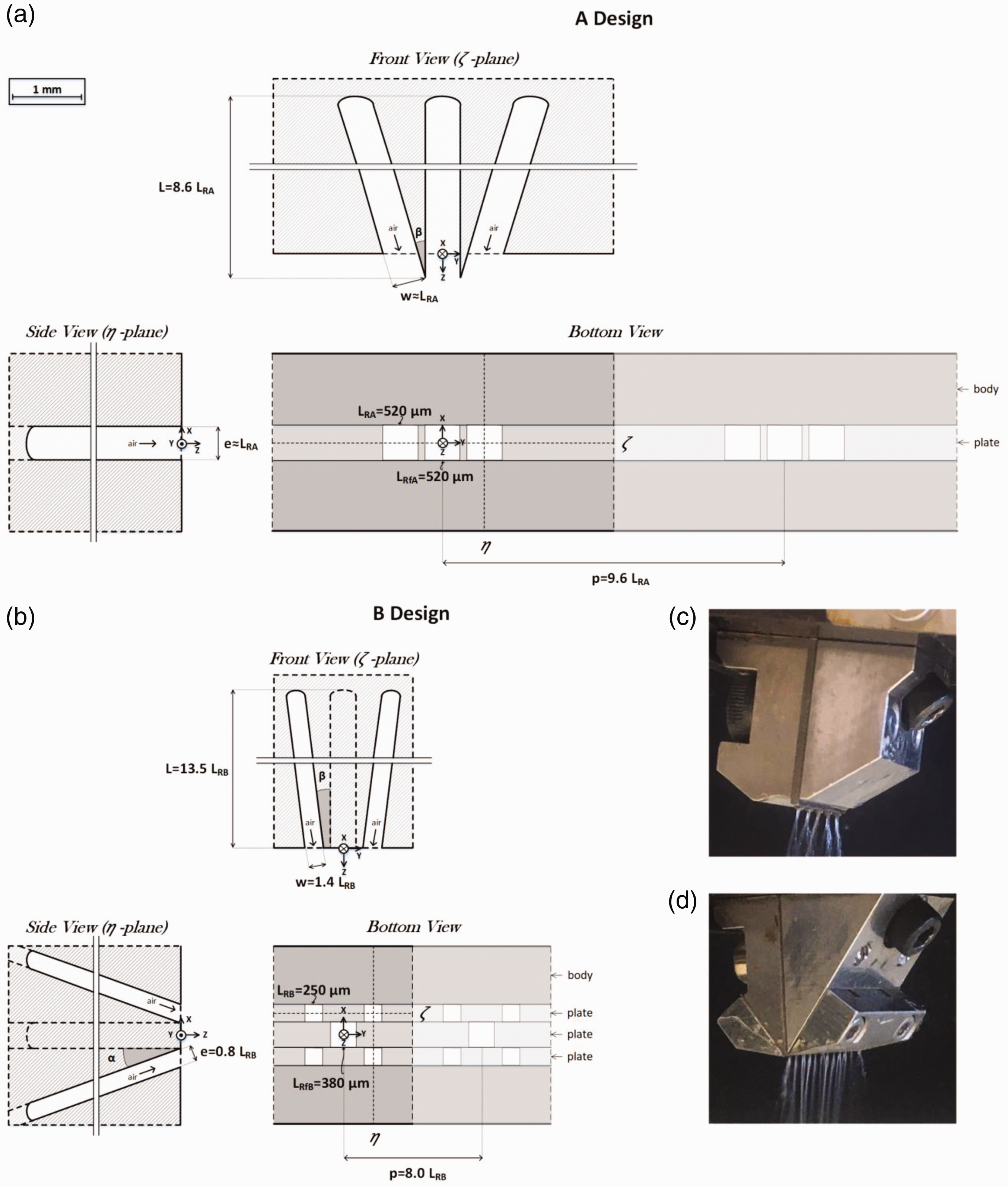
Dimensions and parameters defining the nozzle designs: (a) A design and (b) B design. Photos of the nozzles dispensing adhesive: (c) A design and (d) B design.
Polymer characterisation
Hot melt adhesives are mainly composed of a high molecular copolymer, resin and wax [16]. This type of adhesive is commonly solid at ambient temperature, becomes tacky as it is molten and forms a strong adhesive bond as it cools. The adhesive used in the present study is a typical commercial construction polymer (whose commercial name is PM357V) used in the manufacturing of hygiene products, such as diapers and sanitary napkins. The adhesive is manufactured by the company Savaré. More precisely, this is a styrene butadiene styrene (SBS) based adhesive, whose formula includes other components such as hydrocarbon resins, oil minerals and less than 3% in other additives. Based on thermoplastic rubber, its viscosity is 1.6 and 7.3 Pa·s at 170 °C and 130 °C, respectively, presenting a similar thermal behaviour to other hot-melt adhesives used for sanitary applications [17]. Its softening point is about 76 °C (ASTM E 28, water), its flash point is over 200 °C and its maximum running temperature is 170 °C, which establishes the maximum value for the polymer operation temperature in the experiments.
Figure 2 shows the shear viscosity curve of the adhesive, which is given by the Cross Model, from which

Adhesive’s viscosity as the function of the shear rate at
Experimental facility used for high-speed imaging
Given the velocity of the fibre dynamics present in the melt blowing of hot-melt adhesives, high-speed imaging must be used to capture the fibre oscillation frequency at the nozzle exit region. The experimental facility was comprised of a high-speed camera (Photron FASTCAM Mini AX200) and a cold light source (Tungsten Light Head COOLH dedocool). In order to obtain a sharp contrast between the fibre and the background the images were recorded under backlight conditions. A micrometer allowed the positioning of the camera in the
Operating conditions
A two-level, full factorial design of experiments for three operating factors was adopted as the experimental scheme. To this end, the following operating parameters were selected: the air flow rate
Operating conditions established for the HSI.

In the following, some dimensionless parameters will be defined in order to express the operating conditions of Table 1 in a more compact way. First, a number that considers how much air is destined to a single polymer fibre will be defined as:
See the notation section for more information on the quantities. This number will be designated as the air-polymer flux ratio and has already been used in the past by other authors to study how the operating parameters affect the MB process [18,19]. Second, a number that indicates the relative temperature of the air to that of the fibre will be defined as:
This number will be designated as the dimensionless temperature ratio. This dimensionless parameter is similar to the air-polymer temperature ratio defined by R. Shambaugh [18], but it also takes into account the ambient temperature, which was measured by means of a thermometer in all the experiments. Table 2 shows the experimental conditions of Table 1 in non-dimensional form. When performing the measurements, one repetition was conducted for each operating condition of Table 2.
Operating conditions established for the HSI in dimensionless terms.

Measurement procedure of fibre position and whipping frequency
A tailored Matlab program has been developed for analysing the images from the HSI system and determining the
Once 
Where the fibre’s spreading rate
In order to avoid introducing undesirable effects due to temporal aliasing, the maximum frequency fitted in the models has been limited to be lower than the Nyquist frequency, which is defined as half the sampling rate of the signal, which turns out to be 7,200 and 9,600 Hz in the A and B designs, respectively. The spatial aliasing effects were also considered by setting the maximum wavelength to a fraction of the cameras VFOV. No measurements were performed in those cases in which any type of fibre breakup occurred. Additionally, as the camera’s Horizontal Field of View (HFOV) accounts for a maximum lateral displacement of 1.6 and 1.1 mm in the A and B designs, respectively, occasionally part of the fibre left the cameras FOV, and the position of the points outside the FOV was considered to be half the cameras HFOV. Figure 3 contains two images that illustrate the measuring procedure followed to calculate the fibre’s position in experiments A3 and B1, respectively. The fibre centreline is represented by a yellow line and the vertical tilted dashed lines indicate the fibre wedge, inside which the fibre oscillates, and which are calculated as the maximum displacement of the fibre in the

Measurement procedure followed for determining the fibre position
Results
Fibre dynamics
V. Entov and A. Yarin [21] developed the bending instability theory of liquid jets, which determines the critical air velocity to be

Fibre position
The process of searching for the fibre’s frequency of oscillation
Based on the literature review conducted on the modelling of the path described by blown fibres, it can be concluded that there is no universal model for describing the dynamics of the MB fibre. On the one hand, some authors observed that, although the dynamics described by the fibre in a slot nozzle can be considered to be planar, the one described in a swirl nozzle responds to a helicoidal curve [7]. On the other hand, other authors observed that, when produced with a slot nozzle, the fibre describes a three dimensional oscillatory motion and both its whipping frequency and amplitude present a different value in the
In view of this, and as commented in the Measurement procedure of fibre position and whipping frequency section, the fibre dynamics will be described by means of the equation of a mechanical travelling wave (equation (3)), which excludes from the analysis all the experiments that present any sort of fibre breakup (B2, B4, B5, B6 and B8) and the formation of disturbing fibre loops (B7). Thus, only two experiments will be studied on the B nozzle design. The initial values which were set in the search for the frequency 
Using the values of
Parameters obtained for the

Figure 5 presents a boxplot containing the obtained

Frequencies of oscillation
The effective frequencies obtained in the present study are consistent with the frequencies that have been measured by other authors on other nozzle designs. For example, S. Xie et al. [5] observed frequencies of about 400 Hz, when studying the fibre whipping motion on a dual slot nozzle at an air pressure of 0.1 MPa, an air temperature equal to 260 °C and a polymer flow rate of 2.6 g/min using a polypropylene with Melt Flow Index (MFI) equal to 900. More recently, the same authors observed frequencies of about 700 Hz [23], when conducting high-speed imaging at 4 mm from the nozzle exit, operating at an air pressure of 1 atm. Concerning the effect of the nozzle design on the fibre frequency of oscillation, H. Beard et al. [6] studied the frequency spectra of the fibre oscillation through the use of the Fast Fourier Transform on a slot and on a swirl nozzle designs and concluded that the dominant frequency of the slot nozzle is about
Figure 6(a) presents the effective frequency

Effective frequency
Model of the application pattern
Equation (3) describes the motion of the adhesive fibre on the
With the aim of obtaining a mathematical model to predict the deposition of the adhesive pattern, the motion of the adhesive fibre will be described as a sinusoidal three-dimensional path, as it travels from the nozzle exit to the collector screen. Moreover, it will be assumed that the dynamics of the fibre presents a different amplitude and frequency in the 

For simplicity in the notation, the amplitudes in the
Images of real hot-melt patterns were recorded on the collector screen in experiments A3 and B1 and were used to obtain the parameters required by equation (5) to allow modelling the adhesive pattern (see Figure 7). The images were recorded with
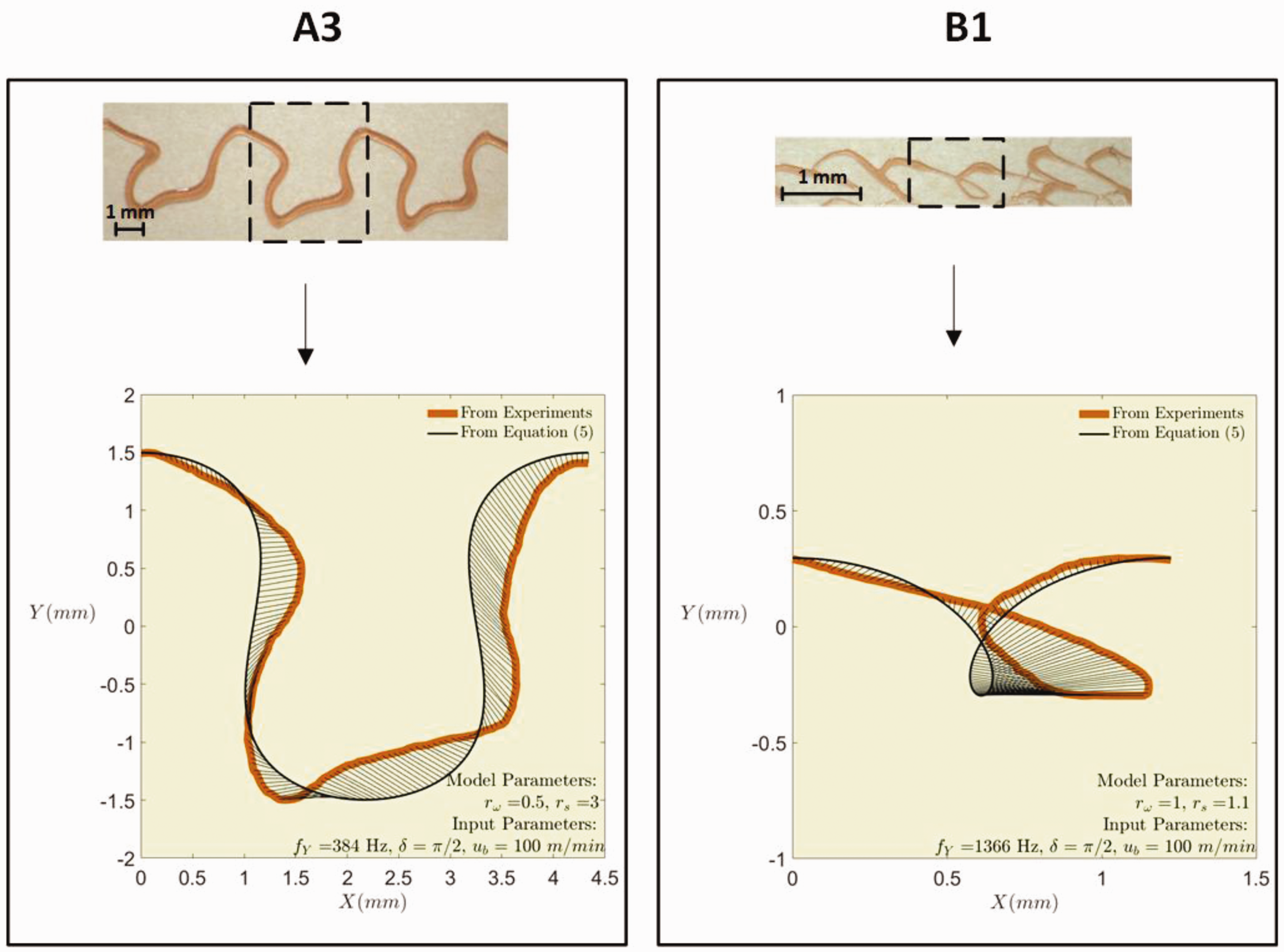
Real (top) and modelled (bottom) application patterns at
Equation (5) requests two input parameters that contain information on the fibre dynamics on the
Equation (5) also gives two model parameters that provide information on the dynamics in the
The range and the step size which were set for the search of
Variation and results obtained for model parameters

The search ranges presented in Table 4 have been refined based on the results obtained from a first precursory search. Figure 7 shows the real adhesive patterns (top) and the modelled ones (bottom) for experiments A3 and B1. The difference between the corresponding points in both patterns is depicted by black solid lines.
The values obtained on parameters
Fibre contact
The simplicity of equation (5) facilitates investigating the main defects that can show up in the adhesive pattern, such as fibre contact, which occurs due to the whipping motion of the fibre in the direction of the moving collector screen

Deposited adhesive pattern at
Fibre contact is avoided if the absolute velocity of the fibre in the 
While equation (6) represents a general condition for avoiding fibre contact, regardless of the nozzle design that produces the pattern, it turns out to be a necessary condition to avoid fibre contact in the B design, but it represents just a sufficient condition for the A design. The parity of
Discussion
Fibre dynamics
Regarding the fibre’s wedge exponent, Table 3 shows that, in general,
In agreement with these observations, E. Moore et al. [9] observed
Regarding the fibre’s whipping frequency, in Figure 6(a) it can be observed that increasing values of
4.2 Fibre contact
From equation (6), the following two observations on fibre contact can be pointed out: Increasing values of Increasing values of
From the first observation, it can be inferred that fibre contact can be minimised by setting the shortest
Finally, notice that equation (6) has been obtained from equation (5), which holds for the nozzle exit region. However, as
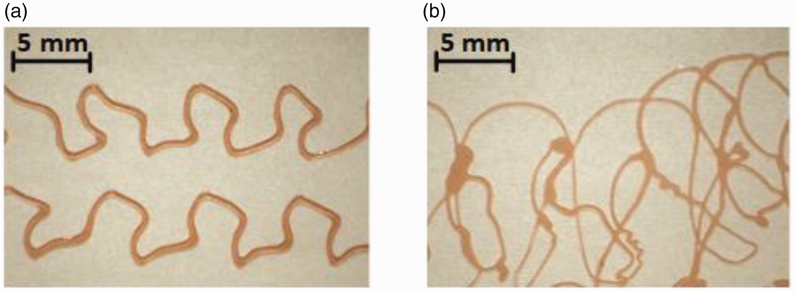
Application pattern for two die-to-collector distances, experiment: A3 (a) DCD = 10 mm and (b) DCD = 30 mm.
The two observations given above are valuable from an economical point of view because the reduction of fibre contact would translate into a reduction in the adhesive over spraying, and ultimately in its waste. The production of adhesive strands with no fibre contact present additional desirable features, such as good pattern definition, breathability, permeability, softness and pattern stability. The production of adhesive patterns at operating conditions that are proximate to the fibre contact condition increase the coverage density of the pattern and simultaneously avoid over spraying. Additionally, if
Concluding remarks
In this article, the fibre dynamics of two melt blowing nozzle designs for producing hot-melt adhesives have been studied by means of HSI. Information about the parameters that govern the fibre dynamics, which include the frequency of oscillation, were obtained through image analysis for the two nozzle designs. The effective frequency
The fibre dynamics in the direction parallel to the movement of the collector screen was inferred by fitting the parametric Lissajous equations to real images of hot-melt patterns. The results obtained suggest that the path followed by the fibre produced by multi-hole nozzles is three-dimensional and, in the case of the A design, its dynamics present significant differences in the
Supplemental Material
sj-pdf-1-jit-10.1177_1528083720978401 - Supplemental material for Experimental study on the hot-melt adhesive pattern produced by melt blowing nozzle designs
Supplemental material, sj-pdf-1-jit-10.1177_1528083720978401 for Experimental study on the hot-melt adhesive pattern produced by melt blowing nozzle designs by Ignacio Formoso, Alejandro Rivas, Gerardo Beltrame, Gorka S Larraona, Juan Carlos Ramos, Raúl Antón and Alaine Salterain in Journal of Industrial Textiles
Supplemental Material
sj-pdf-2-jit-10.1177_1528083720978401 - Supplemental material for Experimental study on the hot-melt adhesive pattern produced by melt blowing nozzle designs
Supplemental material, sj-pdf-2-jit-10.1177_1528083720978401 for Experimental study on the hot-melt adhesive pattern produced by melt blowing nozzle designs by Ignacio Formoso, Alejandro Rivas, Gerardo Beltrame, Gorka S Larraona, Juan Carlos Ramos, Raúl Antón and Alaine Salterain in Journal of Industrial Textiles
Footnotes
Acknowledgements
The authors are grateful for the support of VALCO MELTON for lending the MB equipment, and the Cátedra Fundación Antonio Aranzábal-Universidad de Navarra is also gratefully acknowledged. The authors also want to acknowledge Juan Villarón for the immense help he provided in the laboratory.
Declaration of conflicting interests
The author(s) declared no potential conflicts of interest with respect to the research, authorship, and/or publication of this article.
Funding
The author(s) disclosed receipt of the following financial support for the research, authorship, and/or publication of this article: This work was supported by VALCO MELTON; and Ministerio de Ciencia e Innovación, Gobierno de España, RETOS-COLABORACION 2019 (RTC2019-007057-7).
Supplemental Material
Supplemental material for this article is available online.
Appendix
References
Supplementary Material
Please find the following supplemental material available below.
For Open Access articles published under a Creative Commons License, all supplemental material carries the same license as the article it is associated with.
For non-Open Access articles published, all supplemental material carries a non-exclusive license, and permission requests for re-use of supplemental material or any part of supplemental material shall be sent directly to the copyright owner as specified in the copyright notice associated with the article.