
Abstract
In this study, the flexural and impact properties of hybrid composites including the thin-ply unidirectional (UD) carbon fibers and basalt fabrics with different stacking sequences were investigated. Hybrid composites were fabricated by 2 layers of thin-ply UD carbon fibers and 6 layers of basalt fabrics in which the position of thin-ply UD carbon fibers was changed from the center to the outermost layers for different samples. Results indicated that by embedding the thin-ply UD carbon fibers in the laminates, both flexural and impact properties of the samples were considerably improved. The highest flexural strength (451 MPa) and modulus (37 GPa) values were achieved when the thin-ply UD carbon fibers were placed at the outermost layers; these values were respectively 24% and 44% higher than those of the sample without these fibers. However, results indicated that by placing the thin-ply UD carbon fibers at the center of samples, the failure behavior of samples was changed from catastrophic failure to progressive; and a pseudo-ductile behavior was observed in the mentioned samples. The highest pseudo-ductile strain value of 0.0054 was obtained by placing the thin-ply UD carbon fibers at the center of samples. Similar to the trend pseudo-ductility of samples, the flexural strain of samples improved by nearing the thin-ply UD carbon fibers to the center of samples. Similar to the flexural strain of samples, the results of Charpy impact tests indicated that by nearing the thin-ply UD carbon fibers to the outermost layers, the absorbed energy values decreased.
Keywords
Introduction
Fiber-reinforced polymer (FRP) composites have received considerable attention in many industries owing to their outstanding properties such as low density, high specific strength, high stiffness, and high corrosion resistance. However, the low toughness of the FRP composites is their main drawback [1–3]. Therefore, improving the toughness of polymeric composites is one of the most interesting topics for researchers. The inherent properties of the polymeric matrix act a significant role in the toughness of the composites. Accordingly, the toughness of polymeric composites can be enhanced using thermoplastic matrixes [4,5].
The type of reinforcement is one of the important factors in the ductility of the FRP composites. Metallic fibers can improve the fracture toughness of FRP composites but their high density has restricted their wide applications. On the other hand, high-toughness polymeric fibers have low stiffness and strength values. Due to the mentioned associated problems of FRP composites reinforced with metallic and polymeric fibers, many researchers have focused on the enhancement of the toughness of the polymeric composites using fibers hybridization [6,7]. The main purpose of fibers hybridization is the achievement of the properties of both used fibers in the composites. Generally, the fibers with high strength are combined with another type of fibers with high ductility to achieve the hybridization effects. In general, the properties of used fibers and their configuration in composites can determine the overall properties of hybrid composites [8–11].
Moreover, the failure behavior of composites can be changed from catastrophic to gradual failure which is defined as the pseudo-ductility phenomenon. The occurrence of the pseudo-ductility phenomenon is greatly depending on various parameters. Up to now, extensive works have been performed regarding the fabrication of the pseudo-ductile hybrid composites. In related literature, researchers have indicated that the delamination phenomenon can be delayed using the thin-ply unidirectional (UD) fibers instead of the interplay architecture of fibers [12–15]. Czél et al. [15] fabricated the pseudo-ductile thin-ply UD carbon/glass fibers hybrid composites and their results indicated that the tensile properties of the obtained composites were comparable with tensile properties of metals. In performed studies, the glass fibers have mainly been used for combination with the thin-ply UD carbon fibers for the fabrication of pseudo-ductile hybrid composites [14–18].
Basalt fibers are a type of natural and green fibers that have several outstanding properties such as high mechanical strength, high chemical stability, good resistance to high temperature, non-toxicity, non-combustibility, and high resistance to ultraviolet radiation. Recently, basalt fibers are used as an alternative for the glass fibers [19–22]. The hybridization of the basalt and carbon fibers was investigated in some studies. For example, Najafi et al. [7] reported that the poor impact behavior of the carbon fiber-reinforced polymer (CFRP) improved by the inclusion of the basalt fibers reinforced polymer (BFRP). In another investigation, the effect of the stacking sequence of the fibers on the flexural properties of the basalt/carbon fibers composites was studied by Subagia et al. [23]. Their results indicated that the flexural properties can be optimized by designing the composites with a proper stacking sequence of fibers.
Khalili et al. [24] investigated the effects of thermal cycling on the tensile properties of polymeric composites reinforced with carbon fibers, basalt fibers, and hybrid of basalt and carbon fibers. Their results showed that by increasing the number of thermal cycles, the tensile strength and modulus of samples decreased. However, the degradation of tensile properties of composites reinforced with carbon fibers was higher than those of samples reinforced with basalt fibers and hybrid basalt and carbon fibers. In another study, Eslami-Farsani et al. [25] investigated the impact properties of polymeric composites reinforced by basalt and carbon fibers subjected to thermal cycling conditions. Their results revealed that the absorbed energy values of all composites decreased as a function of thermal cycles. However, the absorbed energy values of composites reinforced with basalt fibers were than those of samples with carbon fibers. On the other hand, the reinforced composites with carbon fibers were lower susceptible to impact damages by thermal cycling. The properties of hybrid composites reinforced with carbon and basalt fibers were between the mentioned composites.
The stacking sequence of fibers is an influencing factor in the properties of hybrid composites. The mechanical properties of hybrid composites reinforced with basalt fibers and carbon fibers with different stacking sequences were investigated by Sun et al. [26]. Their results showed that the stacking sequence of fibers had no significant effects on the tensile properties of samples while its influence on the flexural properties was considerable. The highest flexural strength and flexural modulus values were obtained by placing the carbon fibers at outermost layers. However, by placing the basalt fibers at outermost layers, the lowest flexural properties were achieved. However, to the best of the authors’ knowledge, there is no report on the incorporation of thin ply UD carbon fibers in the BFRP layers. Therefore, this study aims to investigate the effect of stacking sequence on the flexural and Charpy impact properties of thin-ply UD carbon/basalt fibers/epoxy.
Experimental procedure
Materials
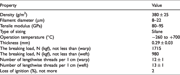
In this study, the basalt fabrics (380 g/m2 sateen woven, ARMBAS, Armenia) and thin-ply UD carbon fibers (38 g/m2, TeXtreme, Sweden) as reinforcements, and epoxy resin (EPL 1012, with hardener EPH 112) as the matrix were used for the fabrication of composites. The main properties of basalt fabrics and thin-ply UD carbon fibers were presented in Tables 1 and 2, respectively. It is worth noting that the resin to hardener ratio was 100:13, as recommended by the manufacture.
The main properties of used basalt fabrics.
The main properties of used thin-ply UD carbon fibers.

Fabrication of composites
The composites were prepared using the hand lay-up method. After lamination of the layers, the pressure of 0.05 MPa was applied to the samples to reduce the void content of composites. All hybrid composites were fabricated using 6 layers of basalt fibers and 2 layers of thin-ply UD carbon fibers. After that, the samples were maintained at room temperature for 7 days, to complete the curing process. The average size of the sample was 7 × 13 × 1.5 mm. Moreover, the average weight ratio of the basalt fabrics/epoxy layers to thin-ply UD carbon fibers/epoxy layers in all samples was 0.05:0.95. In this research, the samples were prepared by different stacking sequences of fibers. The schematic illustration of the fabricated composites is shown in Figure 1. The position of the thin-ply UD carbon fibers changed in samples; the B and C are the signs for basalt and thin-ply UD carbon fibers, respectively. In the mentioned codes in Figure 1, The number after B (or C) means the layer number of basalt fabrics (or carbon fibers). There weren’t any considerable changes in the thickness of samples, after embedding the thin-ply UD carbon in the laminates.

The schematic illustration of the fabricated composites.
Characterization
To investigate the effect of stacking sequence of fabrics in the mechanical properties of samples, the three-point bending and Charpy impact tests were carried out. For each type of composite, three samples were tested, and then the average results were reported. The three-point bend tests were conducted at ambient temperature according to the ASTM D790 standard [27]. Equations (1) to (3) were respectively used for calculating the flexural strength, flexural modulus, and strain at first failure of the samples.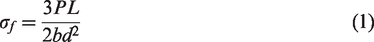


The scanning electron microscopy (SEM, TESCAN) images were used to characterize the fracture surface of the composites. Before all FESEM observations, the samples were cleaned with deionized water, to remove the contaminations. Then, the samples were sputtered with gold to prevent the occurrence of the charging phenomenon.
Results and discussion
Flexural properties of samples
Figure 2 shows the flexural load-deflection curves of the prepared samples with different stacking sequences of basalt fabrics and thin-ply UD carbon fibers. The hybrid composites with different stacking sequences have different flexural properties and their failure behavior of samples is completely different. As can be seen in Figure 2, by placing the thin-ply UD carbon fibers near the center of composites, the failure behavior of samples has been changed from catastrophic failure to a progressive one. So, it can be deduced that the pseudo-ductile phenomenon occurs when the thin-ply UD carbon fibers are placed in the center of samples, during the bending tests. In general, two samples of [B3C2B3] and [B2CB2CB2] samples with pseudo-ductile strain values of 0.0054 and 0.0033 show only the pseudo-ductility. However, the flexural behavior of other samples is catastrophic. Besides, the first load drop of samples containing thin-ply UD carbon fibers is lower than that of the sample without these fibers ([B6] sample). It is clear that with increasing the load drop, the integrity of laminates decreases. Therefore, the inclusion of thin-ply UD carbon fibers in the laminates had a positive effect on the failure behavior of samples. According to the higher pseudo-ductile strain of [B3C2B3] sample (0.0054) in comparison with samples[B2CB2CB2] samples, this sample can be introduced as the optimum sample, from the viewpoint of pseudo-ductility.
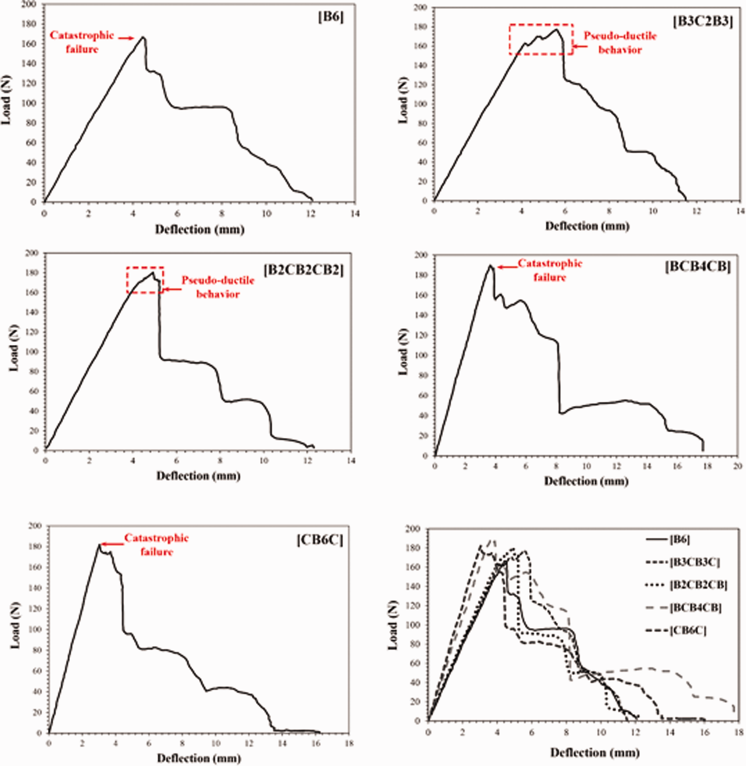
The flexural load-deflection of the composite samples.
The flexural properties of samples including the flexural strength, flexural modulus, and strain at first failure have been shown in Figure 3. By embedding the thin-ply UD carbon fibers in the BFRP layers, the flexural properties including the flexural strength, modulus, and strain values have been changed, considerably. The efficiency of the thin-ply UD carbon fibers in improving the flexural properties of BFRPs significantly depends on their position in the laminates. In bending tests, the samples are undergoing the complex loadings; the compressive and tensile loads are applied on two sides of samples during the bending tests [7,29,30]. From Figure 3(a) and (b), it can be deduced that as the thin-ply UD carbon fibers are placed at the outermost layers, the flexural strength and flexural modulus values increase, in comparison with other samples. For the final failure of samples during bending tests, different steps occur. At first step, the compressive failure of the outermost layer occurs and so, the mechanical properties such as flexural modulus improve by placing the thin-ply UD carbon fibers at the outermost layers. For example, the flexural strength and flexural modulus of 451.13 MPa and 37.12 GPa have been achieved for the [CB6C] sample; these values are respectively 6.76% and 41.18% higher than those of [B3C2B3] sample. This observation can be related to the higher mechanical properties of thin-ply UD carbon fibers, compared to the basalt fibers. The flexural strength and flexural modus have a similar tendency as a function of the stacking sequence of fibers. However, the stacking sequences of fibers have more influence on the flexural modulus of samples, as shown in Figure 3(b). In other words, by changing the position of the thin-ply UD carbon fibers from the center of the samples to the outermost layers the flexural modulus value of the sample has increased from 26.17 GPa to 37.12 GPa. In general, an increasing tendency is observed for the flexural strength and modulus of the samples by nearing the thin-ply UD carbon fibers to the outermost layers.

The flexural properties of composites with different stacking sequences (a) flexural strength, (b) flexural modulus and, (c) strain at peak.
However, as shown in Figure 2, by placing the thin-ply UD carbon fibers in the center of samples, a pseudo-ductile behavior was observed. The pseudo-ductile behavior of samples can be related to the occurrence of delamination phenomenon during the bending tests. However, the strain at first failure of the sample has decreased by placing the thin-ply UD carbon fibers at the outermost layers; the highest strain values (0.021) have been achieved for the [B3C2B3] sample. The strain at first failure [B3C2B3] sample is about 23% higher than that of the [B6] sample (0.017). Although the carbon fibers are brittle, the improvement in the strain values of samples by the inclusion of the thin-ply UD carbon fibers in the laminates can be due to the delamination phenomenon caused by creating different interfaces. From another viewpoint, the strain values have decreased by the addition of the thin-ply UD carbon fibers near the outermost layers, significantly. The strain value of the [CB6C] sample is about 33% lower than that of the [B6] sample. Although the flexural strength and modulus of the samples have not improved considerably by placing the thin-ply UD carbon fibers in the center of samples, the strain at first failure has increased and also a pseudo-ductile behavior occurred. Therefore, the mentioned results show that for improving the flexural strength and modulus, placing the thin-ply UD carbon fibers at both sides of samples (compressive or tensile sides) is suggested. On the other hand, for decreasing the sudden failure of samples during the bending tests, the thin-ply UD carbon fibers should be placed at the center of samples.
These results are in agreement with results of Prusty et al. [30]. They investigated the effects of stacking sequence of fibers on the flexural properties of glass-carbon-epoxy hybrid composites. Their results showed that the highest flexural strength and modulus values were achieved for the samples by carbon fibers at outermost layers. They also reported the occurrence a pseudo-ductile behavior for the samples in which the carbon fibers placed near the center of samples. Besides, the similar results were reported by Sun et al. [26].
Charpy impact behavior of samples
Figure 4 shows the specific absorbed energy of the samples after Charpy impact tests. In general, by placing the thin-ply UD carbon fibers in the laminates, the specific absorbed energy values have improved. However, the position of the thin-ply UD carbon fibers is an influencing factor on the absorbed energy value.

The specific absorbed energy values of the composite samples with different stacking sequences.
The highest energy absorption value (1.309 kJ/g) has been achieved for the [B2CB2CB2] sample that this value is about 70% higher than that of ([B6]) sample (0.767 kJ/g). Contrary to the flexural properties of samples, the specific absorbed energy values have not improved as the thin-ply UD carbon fibers were placed at outermost layers, in which the obtained value of the [CB6C] sample (1.024 kJ/g) is about 22% lower than that of the [B2CB2CB2] sample. This inconsistency can be explained by differences between the bending and Charpy impact tests. In Charpy impact tests, the energy is firstly absorbed by elastic deformation of the material. Then, the excess energy can be absorbed by various mechanisms including the fiber pull-out, fiber breakages, and delamination as ductile manners and matrix cracking as brittle manner [21,22]. However, the flexural properties of hybrid composites, especially flexural modulus, are mainly dependent on the properties of the compressive side of them. The higher absorbed energy values of the [B3C2B3] and [B2CB2CB2] samples compared to other samples can be related to their higher flexural strain and also the occurrence of pseudo-ductility phenomenon. Therefore, the improvement in the toughness of the samples by placing the thin-ply carbon fibers near the center of samples can be introduced as the main reason for their higher absorbed energy values. However, when the thin-ply carbon fibers are placed at the outermost layers, the flexural strain of samples decreases and so, the ductility of the samples reduces. Thereby, the lower absorbed energy values of [CB6C] samples compared to other samples can be attributed to their lower flexural strain and ductility. Similar results were also reported by Subagia et al. Their findings revealed that when the basalt fibers placed at outermost layers the highest ductility was achieved while the highest flexural strength and modulus values were obtained by placing the carbon fibers at outermost layers.
Figure 5 presents the photograph of the impacted samples with a cross-section view, showing different fracture types of the samples. Figure 5(a) indicates the fracture surface of the [B6] sample that shows that the fibers’ breakage is the main energy absorption mechanism of this sample. As can be seen in Figure 5(b), by placing the thin-ply UD carbon fibers at the center of the sample ([B3C2B3]), the occurrence of delamination phenomenon is observed in addition to the breakage of the fibers. The extent of the delamination phenomenon has significantly increased in the [B2CB2CB2] sample. Therefore, the higher energy absorption of this sample can be related to the occurrence of such extensive delamination. However, the extent of delamination again decreased by placing the thin-ply UD carbon fibers at the outermost layers.

Photographs from the fracture surfaces of the (a) [B6], (b) [B3C2B3], (c) [B2CB2CB2], (d) [BCB4CB] and, (e) [CB6C] samples after Charpy impact tests.
Therefore, the lower energy absorption of the [CB6C] sample compared to the [B2CB2CB2] sample can be explained by the occurrence of smaller delamination. These observations are in good agreement with the results of Behnia et al. [31]. They fabricated different hybrid composites reinforced with basalt, carbon, glass, and aramid fibers and investigated the Charpy impact behavior of them. The fracture analyses of their study showed that by placing the carbon fibers at outermost layers, the brittle fracture mechanisms such as fiber breakage and matrix cracking were observed. However, the extensive delamination phenomenon occurred by placing the basalt fibers at outermost layers.
To uptake more insights on the energy absorption of the samples, the fracture surfaces of the [B6], [B3C2B3], [B2CB2CB2], and [CB6C] samples were analyzed by SEM images. Figure 6 illustrates the fracture surface of [B6] sample after the Charpy impact test. The dominant energy absorption mechanisms of this sample are delamination and the fiber pull-out. The fracture surfaces of the [B3C2B3] samples have been also depicted in Figure 7. The occurrence of the delamination phenomenon is the main absorbing mechanism of this sample.

SEM images of the fracture surface of [B6] sample after Charpy impact test with (a) low magnification and (b) high magnification.

SEM images of the fracture surface of [B3C2B3] sample after Charpy impact test with (a) low magnification and (b) high magnification.
The fracture surface of the [B2CB2CB2] sample after the Charpy impact is shown in Figure 8. As indicated by arrows in Figure 8(a), extensive delamination has occurred in this sample. So, the higher energy absorption of this sample in comparison with other samples can be related to the delamination between layers of composites. According to this fact that the used carbon fibers in this study were UD type, it can be said that the anisotropy of the fibers had played a significant role in the impact behavior of the hybrid composites. These results are in agreement with the results of Caminero et al. [29] study. They investigated the effect of stacking sequence of fibers with different orientations on the Charpy impact behavior of CFRP laminates. Their results indicated that the absorbed energy of the samples with different angle ply was higher than that of the unidirectional CFRP. Therefore, the presence of more interfaces with different properties in [B2CB2CB2] can be introduced as the main reason for the occurrence of delamination and consequently, higher energy absorption.

SEM images of the fracture surface of [B2CB2CB2] sample after Charpy impact test with (a) low magnification and (b) high magnification.
The fracture surfaces of the [BCB4CB] sample after the Charpy impact test are depicted in Figure 9. As can be observed in Figure 9(a) and (b), the delamination and fiber breakage mechanisms have occurred for this sample. Moreover, Figure 10 shows the fracture surface of [CB6C] after the Charpy impact test. In addition to the delamination and fiber pull-out phenomena (Figure 10(a) and (b)), the brittle manners of energy absorption mechanisms such as matrix cracking are visible in Figure 10(c) and (d). Thereby, the lower energy absorption of the [CB6C] and [BCB4CB] samples compared to the other configurations can be related to their lower delamination and also the occurrence of brittle manners of energy absorption. So, it can be deduced that when the carbon fibers were placed near the two ends of composites ([CB6C] and [BCB4CB] samples) the impact energy has been absorbed by the delamination, matrix cracking, and fiber breakage.

SEM images of the fracture surface of [BCB4CB] sample after the Charpy impact test with (a) low magnification and (b) high magnification showing different mechanisms of delamination and fiber breakage.

SEM images of the fracture surface of [CB6C] sample after the Charpy impact test showing different mechanisms of (a) delamination, (b) pull-out, (c) matrix cracking, and (d) fiber breakage.
The results of this study are in agreement with the results of the Bozkurt et al. [22] study. In their study, the Charpy impact behavior of the basalt/aramid fibers hybrid composites was investigated. Their results indicated that the neat basalt fibers reinforced polymer (BFRP) composites had higher absorbed energy (119.29%) than that of aramid fiber-reinforced polymer (AFRP) composites. Their results showed that by increasing the volume fraction of the basalt fibers in hybrid composites, the absorbed impact energy was improved. In another study, Najafi et al. [7] investigated the effect of stacking sequence of fibers on the flexural and impact behavior of hybrid basalt and carbon fibers reinforced phenolic composites. They used different volume fraction and stacking sequence of fibers for the fabrication of the hybrid composites. Their results indicated that by increasing the weight fraction of the basalt fibers in the laminates, the energy absorption of the samples was increased, considerably. However, the flexural properties of samples were in contrast with the Charpy impact behavior of samples, in their study. Their results indicated that the flexural properties of samples with higher weight fraction of the carbon fibers were higher than those of samples with lower weight fraction of the carbon fibers. According to the mentioned studies, it can be deduced that the BFRPs have higher energy absorption compared to the CFRPs. Accordingly, the higher energy absorption of the [B2CB2CB2] sample compared to the other samples, can be also related to the occurrence of a more delamination mechanism.
Conclusion
In this research, the hybrid composites including the thin-ply unidirectional (UD) carbon fibers and basalt fabrics different stacking sequences were fabricated. The hybrid composites were prepared using 6 layers of basalt fabrics and 2 layers of thin-ply UD carbon fibers. The composites were fabricated with four stacking sequences of fibers in which the position of the thin-ply carbon fibers changed from the center to the outermost layers. The samples with specimen’s codes of [B6], [B3C2B3], [BCB4CB], [B2CB2CB2], and [CB6C] were fabricated where B and C respectively are related to basalt fabrics and thin-ply UD carbon fibers. Besides, the numbers after B and C indicates the number of layers. Three-point bending and Charpy impact tests were carried out to study the flexural and impact behavior of the hybrid composites. In general, this study revealed that by choosing a proper stacking sequence of fibers, the hybrid composites for applications where ductility value is important or applications in which the strength/modulus values are concern can be fabricated. The main conclusions of this study were as following: Flexural tests indicated that the stacking sequences of fibers had considerable effects on the flexural strength, modulus, and strain values of samples. The highest flexural strength and modulus of 451.13 MPa and 37.12 GPa were respectively obtained when the thin-ply UD carbon fibers were placed at the outermost layers ([CB6C]). The mentioned values were about 24.16% and 44.54% higher than those of samples without thin-ply UD carbon fibers ([B6]). By nearing the thin-ply UD carbon fibers to the center of samples, the highest ductility values were achieved for samples. For example, the strain value of the [B3C2B3] sample was about 90% higher than that of the [CB6C] sample. Furthermore, the failure behavior of samples changed from catastrophic failure to progressive one and pseudo-ductile behavior was observed by nearing the thin-ply UD carbon fibers to the center of samples. The pseudo-ductile strain values of 0.0054 and 0.0033 were achieved for the [B3C2B3] and [B2CB2CB2] samples, respectively. The results of Charpy impact tests indicated that the inclusion of the thin-ply UD carbon fibers in laminated led to the improvement in the specific absorbed energy values. However, the specific absorbed energy values significantly increased by placing the thin-ply UD carbon fibers near the center of samples. These results were similar to the flexural strain values of samples. The highest specific absorbed energy value of 1.309 kJ/g was obtained for the [B2CB2CB2] sample which was about 27% higher than that of the [CB6C] sample.
Footnotes
Declaration of Conflicting Interests
The author(s) declared no potential conflicts of interest with respect to the research, authorship, and/or publication of this article.
Funding
The author(s) received no financial support for the research, authorship, and/or publication of this article.