
Abstract
In advanced engineering applications, machining of composite material is a must to perform necessary assembly operations. This work deals with the investigation of fabrication potential of Glass/epoxy composites reinforced with different textile structures in the form of E-glass based chopped fiber, unidirectional (UD) tow, bidirectional (2D) plain woven, four different 3D woven orthogonal solid structures with varying binder percentage and one 3D woven angle interlock structure. The Influence of reinforcement architecture on tensile strength, drilling damage, bearing response, specific energy absorption (bending), and spring stiffness of composites structure was investigated. Damage analysis due to drilling was primarily assessed in terms of delamination whereas bearing strength, bearing strain and common bearing failure were examined from the bearing strength test. Different bearing failure was observed for different composite structures; UD composite was noticed with complete shear out failure while chopped failed due to tearing and 2D structure reinforced composite predominantly failed due to tearing and delamination failure. 3D orthogonal composite failed due to tearing in the warp direction and shear out in weft direction whereas 3D interlock failed due to tearing in both warp and weft direction. 3D orthogonal based composite structure exhibited the highest specific energy absorption (SEA) along with improved spring stiffness and therefor it could be a potential material for automotive leaf spring application.
Keywords
Introduction
Leaf spring is a load-carrying assembly in automobiles. It absorbs vertical vibrations caused by irregularities in the road. Variations in the spring deflection allow potential energy to be stored as strain energy and then released more gradually over time. Normally leaf spring is joined with vehicle chassis by adhesive bonding or mechanical fastening using nuts and bolts [1]. Figure 1 shows the schematic diagram of leaf spring used in automobiles.

Schematic diagram of leaf spring used in automobile suspension system.
Composites are well suited for leaf-spring applications due to their high strength-to-weight ratio, fatigue resistance, and natural frequency. Internal damping in the composite material leads to better vibration energy absorption within the material, resulting in reduced transmission of vibration noise to neighboring structures. Despite all these advantages it's joining with chassis is always a complex process and it needs fabrication in terms of machining operation like drilling. However, machining of composite materials is difficult to carry out due to the anisotropic and non-homogeneous structure of composites and to the high abrasiveness of their constituent material both matrix (thermoset) and reinforcing constituents. Abrasiveness of reinforcement architecture can hardly be eliminated especially in advance fibers like glass/carbon/aramid etc. due to their brittle behavior. However properties of epoxy can be improved by changing its chemistry, Meng et al. [2] described the viewpoint of synthetic chemistry, noncovalent and covalent approaches for the preparation of carbon nanomaterial/CP composites and discussed the challenges and perspective of each method along with their potential applications. Yang et al. [3], Han et al. [4] work deals with the improvement of thermal conductivity of epoxy composite from synthesized liquid crystal epoxy by doping of boron nitride fillers. The abrasiveness and anisotropicity typically result in damage being introduced into the workpiece and in very rapid wear development in the cutting tool. Several studies were conducted on the drilling behavior of composites reinforced with natural and high-performance fibers in the recent past [5–10], wherein the effect of speed, drill geometry, and feed rate was investigated on thrust force, torque requirement, and machinability of composites. After drilling the joining of leaf spring end to the chassis of the vehicle is the main task, therefore it is important to select the right joining technique to attach the composite leaf spring with vehicle chassis to transfer load effectively between the linked structures. Mechanically fastened bolted joints are the most common due to their better reparability and joint performance [11
Materials, Experimental procedures, and methods
Materials
Multifilament E-glass tows of different linear density 300-2400 tex supplied by Dhingra polymers, New Delhi (India) of make Owens corning) was used to prepare different textile structure used for composite reinforcement. Epoxy LY556 was used as matrix material along with hardener HY951 in the ratio of 10:1 for composite manufacturing.
Preparation of textile preforms
Chopped fibers
The multifilament E- glass tow of linear density 2400 tex was cut into a staple length of 10 mm for chopped fiber reinforced composite preparation. The preparation of Chopped fiber used in this investigation is shown in Figure 1(b) of the supplementary information section of this article.
Unidirectional (UD) and two dimensional (2D) plain woven reinforcement
UD and 2D plain woven fabric is produced on a conventional weaving machine. In UD all the fibers (linear density 2400 tex) are aligned in one direction (warp) with only a few yarns of 300 tex linear density are interlaced in the transverse direction just to hold the structure as shown. Whereas (2D) plain woven fabric was produced with an equal number of yarns of 2400 tex linear density in both warp and weft direction. The cross-section, lifting plan, and developed fabric sample are shown in the Figure 2.

Cross-section, lifting plan and developed UD and 2D fabric sample.
3D orthogonal Fabric
Four different 3D solid orthogonal structures were woven on a customized rigid rapier weaving machine specially designed to produce 3D structures with provisions with provision to accommodate multiple warp beams. Four different multilayer orthogonal structures were produced using 2400 tex yarns in warp and weft direction and binder yarn of 300 tex. Warp yarns are designated as stuffers and weft yarns as fillers throughout the discussion. The cross-section, lifting plan, and developed different 3D solid orthogonal fabrics are shown in Figure 3.

Cross-section, lifting plan, and developed 3D solid orthogonal structures.
3D Interlock Fabric
3D solid interlock fabric structure (shown in Figure 4) was woven on the same loom using 4400 tex stuffer warp and filler weft and 300 tex binder thread. The thread density in all three directions was set to achieve similar areal density (approximately 9000 g/m2) as in case of orthogonal structure. All measured parameters of different textile structures are summarized in Table 1.

Cross-section, lifting plan, and structure of 3D solid Interlock structure.
Measured parameters of various reinforcement architecture and their composite.

Preparation of composite leaf spring
Figure 5 shows the flow chart for the development of composite leaf spring. Teflon-coated semielliptical mold was used to make composite leaf spring using a vacuum-assisted resin transfer molding (VARTM) process. Woven textile structure was cut to the required shape and placed on the mold so that it can take semielliptical shape and then it is covered with peel ply (for easy removal) and resin mesh placed on top of peel ply to stop the flow of resin outside the sample area. Finally, vacuum bagging was fixed with sealant tape to make the process leak proof. After resin infusion, the setup was left for room temperature curing of 24 hours. For chopped fiber reinforced composite leaf spring, fiber resin mixture was placed in the bottom part of the mold and then after closing with top mold appropriate pressure was applied to give it leaf spring-like shape and then left for curing for 24 hours. Measured parameters (fiber volume fraction, density, and thickness) of composite structures are summarized in Table 1.

Development process of composite leaf spring using VARTM.
Post to the development of composite leaf springs, the end section from one side was taken into consideration for the fabrication potential investigation as shown in Figure 6. Since leaf spring is joined to the vehicle chassis from its two ends, therefore one of its ends was cut into the required dimensions to perform drilling operation first and subsequent double bolted joint test for knowing the bearing strength of the different composite leaf spring material. Detailed experimental procedure for drilling and bearing strength test is discussed in “Preparation of composite leaf spring” section of this manuscript.

Geometry of test specimen for drilling and Bearing failure test.
Characterization
Tensile properties
Tensile properties of different textile structural composites investigated in accordance with ASTM D3039 standard. The test was conducted at a strain rate of 2 mm/min, a total of five samples (250 mm×25 mm) was tested and the average value was taken. INSTRON 100 KN universal testing machine was used for tensile testing of composites.
Drilling of composites
Different textile structure reinforced composite leaf spring materials were investigated for their fabrication potential in terms of drilling and bearing response. Drilling was performed using a floor-mounted drill attached with a carbide-based rill bit of 6 mm size. The composite sample was fixed into a wooden board using a C- clamp on the drill machine platform to perform accurate drilling at the marked position. The typical test setup for drilling of composites is shown in Figure 1(c) (a) of the supplementary information section of this article. All the drilled samples were subsequently tested for the double bolted joint bearing response.
Bearing (Joint performance test)
Bearing response were determined with the help of in house fabricated test fixture shown in Figure 1(c) (b) of the supplementary information section of this article, the fabricated setup was integrated with existing INSTRON 5982 universal tensile tester according to ASTM D 5961 standard. The test was conducted at a strain rate of 5mm/min in ambient room condition at 27°C and 60% humidity. The effect of reinforcement architecture on their bearing strength and bearing failure was recorded from this test. Three tests were conducted for each configuration and the average value presented.
Specific Energy absorption and spring stiffness under bending (3 point)
Flexural properties of structural composites fabricated for leaf spring were tested according to standard ASTM D 790 using INSTRON (3365) universal testing machine of 5KN capacity. Specimen size for flexural testing was 120 mm×19 mm with a span to thickness ratio of 16:1. The strain rate was kept at 1 mm/min. An average of five observations was recorded for determining the specific energy absorption (bending) of the composite from the three-point bending test shown in Figure 1(d) of the supplementary information section of this article. Specific strain energy absorption was calculated using equation 1
Results and Discussion
Tensile properties of different composite structures
Table 2 shows the tensile strength of different textile structural composite and conventional steel used in leaf spring application. Since both the materials have significant difference in their density, therefore comparison of specific strength was made. Specific tensile strength composite reinforced with textile structure (UD, 2D and 3D ortho composites) found higher than conventional steel. Whereas specific strength of Chopped and 3D Inter (Warp) direction found lower than steel. It is clear from the results that textile structural composites could be a potential material for leaf spring application. It is clear from the results that tensile stresses of UD, 2D, and 3D composites were found in the range of design load stress (DLS) required for the suspension system of different vehicles which is typically in the range of 300 to 550 MPa for heavy vehicles like bus and trucks and 600 to 750 MPa for the light passenger vehicle [22]. UD composite gives the highest tensile strength followed by 2D Plain, 3D orthogonal, and 3D interlock reinforced composites depending on the order of disposition of fibers along a particular direction. This is because UD composite has all the fiber in one direction, in 2D fibers was distributed in two directions, and in 3D fibers distributed in three mutually perpendicular directions. Though UD and 2D composites have higher tensile stresses than 3D composites for comparable volume fraction, but they are prone to delamination (separation of staking layer) at higher loads which ultimately will lead to failure. It was also reported by Khatkar et al. [23] that UD and 2D composites have undergone a higher degree of delamination compared to 3D composites.
Tensile properties of different textile structural composites.

Figure 7 shows the tensile fractured samples of different composite structures. The opaque region in UD and 2D plain indicate internal damage of composites which results in delamination. Whereas in 3D composites delamination was found negligible, the opaque region in 3D Orthogonal and interlock was due to surface crazing because of matrix cracking at the point of Z binder reinforcement. Dai et al. [24] also investigated the influence of z binder yarn on the tensile, compressive and flexural behavior of 3D woven composites and made similar observation in their fracture behavior. Further, it is important to know their fabrication potential to have their applicability in automotive leaf spring.

Tensile fractured different textile structural composite.
Drilling Behavior
To perform assembly operations in composite structures drilling hole is an important operation required to perform. Therefore the developed composite structures must be investigated for their drilling potential and the associated damage with regards to drilling. Drilling parameters like speed, drill geometry, and feed rate may significantly affect the drilling characteristics of composite laminates. However, this investigation is limited to the influence of drilling on composite structures reinforced with different textile structures. The influence of drilling was analyzed in terms of various defects induced due to drilling. Drilling of composites is likely to develop various defects like burrs, tearing, delamination, fiber pullouts, and matrix degradation due to their inherent anisotropicity in mechanical properties [5

Different drilled textile structural composites (a) chopped front (b) chopped Back (c) UD front (d) UD Back (e) 2D front (f) 2D back (g) 3D 1 front (h) 3D 1 back (i) 3D 2 front (j) 3D 2 back (k) 3D 3 front (l) 3D 3 back (m) 3D 4 front (n) 3D 4 back (o) 3D Inter front and (p) 3D Inter back.
Bearing Characteristics
Bearing properties of Chopped, UD, 2D, 3D Ortho, and 3D Interlock composite structures
Figure 9 shows the typical bearing stress-strain curve obtained from bearing test of chopped, UD, 2D, 3D Orthogonal, and 3D Interlock composites. A similar type of curve was obtained for different composite structures. It can be seen from the curve that the initial portion of the curve is flat along the horizontal axis this could be due to the presence of clearance between bolt and hole. Later the curve shows a linear response till it reaches the peak load and finally, the drop in load was noticed when the fibers start moving along with the bolt motion. Bearing stresses were calculated using equation 2 where P is the maximum bearing load, d is the hole diameter and t is the average specimen thickness.

Typical bearing stress strain curve of chopped, UD, 2D plain, 3D ortho and interlock composite structures.
Bearing strain was calculated using equation 3. Where 
Figure 10 shows the comparison of the bearing strength of chopped, UD, 2D Plain, 3D Ortho (3S4B, 13% binder percentage), and 3D Interlock composite structures. Bearing strength was found in order of 2D > CHOPPED> 3D Inter > 3D Ortho >UD respectively. Composite reinforced with 2D plain weaved architecture depicted the highest strength with a value of 192 ± 3.2 MPa for identical volume fraction and areal density. This could be inferred because in 2D plain reinforced composite 50% of the fibers were present in the direction perpendicular to the loading direction, which is causing the maximum hindrance to the bolt while performing the bearing test. The bearing strength of UD composites was found lowest with a value of 39 ± 0.9 MPa this was because all the fibers were present in loading direction which poses a negligible obstruction to the bolted joint. Whereas the strength of chopped fiber-reinforced composite (CFRC) was found higher than 3D reinforced composites (Orthogonal and Interlock) because fibers are randomly distributed in multiple directions in CFRC which cause the higher resistance to the bolted joints whereas in 3D composite structures composite fibers were arranged in three mutually perpendicular directions and hence offered lower bearing strength than chopped one. It is interesting to note that the bearing strength in 3D Inter composite was higher than 3D Ortho with very little margin due to better interlocking mechanism in 3D interlock composite structure. Subramanian and Senthilvelan [18] investigated the bearing strength (joint performance) of injection molded 20% glass fiber reinforced polypropylene leaf springs and found that maximum bearing strength of 48 MPa with a strain of 21%. It seems E-glass/epoxy based textile structural based composite leaf spring can be a suitable combination for leaf spring material because of suitability of textile structural composites for load bearing applications [27].

Comparisons of bearing strength for different textile structures reinforced composite.
Figure 11 shows the microscopic images of bearing fractured composite samples. It can be seen that chopped fiber composite failed predominantly due to a combination of tearing and cleavage failure Figure 11(a). While UD composite failed due to complete shear out at the hole along the direction of fibers as shown in Figure 11(b), a possible reason could be due to the all-fiber alignment in the direction of loading and hence offer very low resistance to bearing bolts. 2D composite failed due to tearing at the edges as well an opaque region was noticed near the holes as shown in Figure 11(c), which indicates the delamination due to interlaminar shear stress. The edge tearing could be due to the resistance created by the fibers perpendicular to loading direction and due to poor inter-laminar stress between the stacked layers of 2D composite. Figure 11(d) to (e) shows the failed samples of 3D Ortho and 3D Inter composite which indicates a clear failure of tearing and cleavage in both the 3D reinforced composite structures.
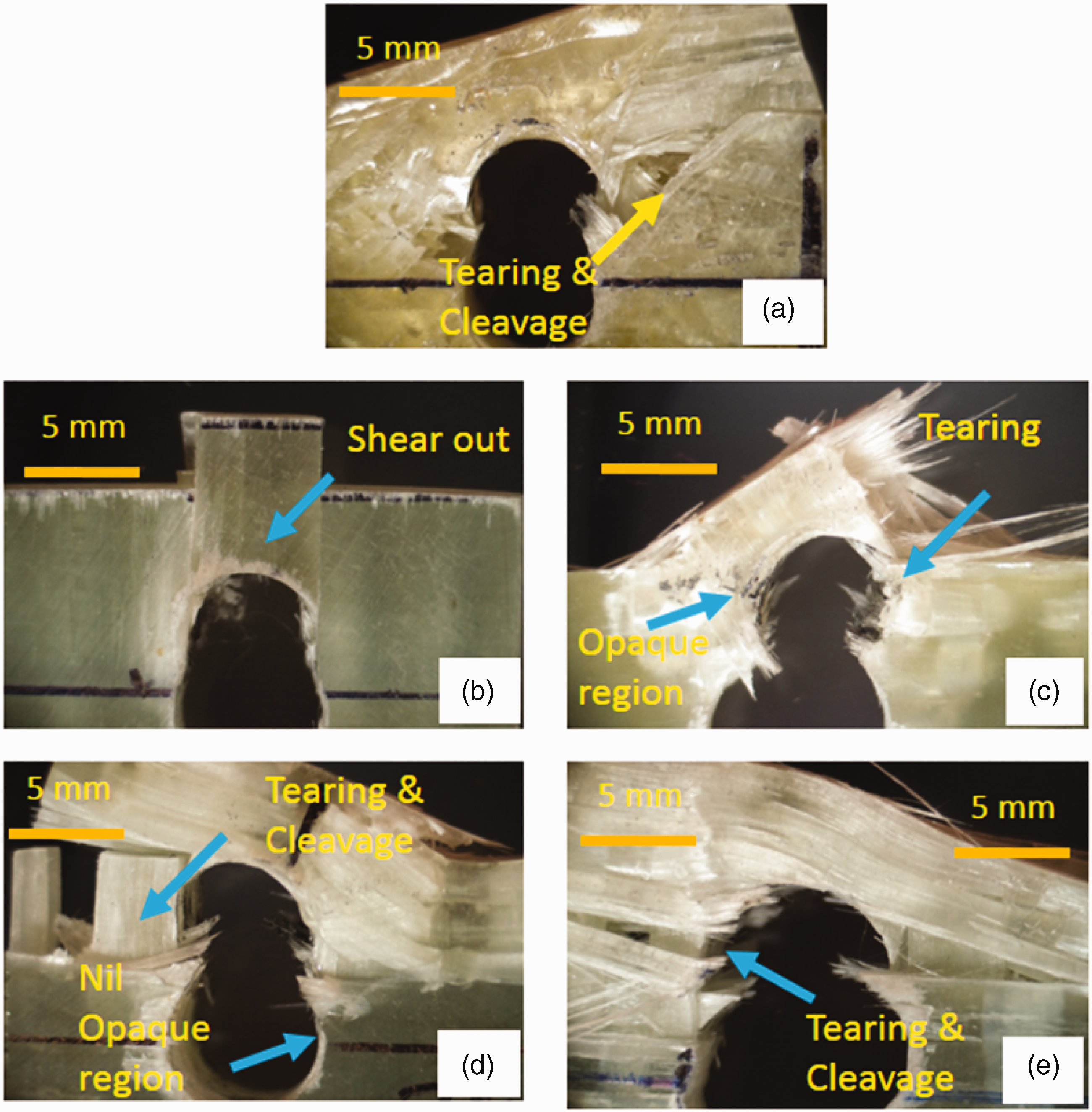
Microscopic images of front view of bearing fractured composite samples (a) chopped (b) UD (c) 2D plain (d) 3D ortho (3S4B) (e) 3D inter.
Figure 12 shows the top view of the bearing fractured samples of 2D and 3D composites which also confirm that in 2D separation of stacked layer i.e. delamination appeared due to applied load, whereas in 3D composites nil delamination noticed along with few matrix cracking sites. Therefore it can be concluded that although bearing strength of 2D composites found highest compared to all other composite structures, but microscopic analysis clearly indicates that 2D composites structures are noticed with opaque region (internal damage) and separation of stacked layer i.e. Delamination whereas 3D noticed with nil delamination.

Microscopic images (a) 2D top view and (b) 3D top view.
Influence of structural variation on bearing properties of 3D orthogonal composite structures
Figure 13(a) and (b) shows the typical stress-strain curves of different 3D orthogonal reinforced textile structural composites obtained from the bearing strength test in warp and weft direction respectively. Structural variation was made in terms of binder yarn percentage variation. 3D orthogonal structures named as 3S1B (3%), 3S2B (7%), 3S3B (10%) and 3S4B (13%) with 3%, 7%, 10% and 13% binder percentage respectively were used for developing composite leaf spring

Typical stress strain curve of 3D orthogonal textile structural composite obtained from bearing strength test (a) 3D warp and (b) 3D weft.
Typical values of bearing strength and bearing strain for different 3D composite structures are summarized in Table 3. It is clear from the test results that the bearing strength of 3S2B, 3S3B, and 3S4B composite structures found almost similar with a variation of 10 to 12% higher values in 3S1B composite structures in warp direction while bearing strength in weft direction noticed with almost equal strength in all four composite structures. This proves that the influence of binder (through-thickness) yarns is negligible on the bearing strength of 3D orthogonal reinforced composites. The possible reason could be the minimum number of crossover points of binder yarn in the test area selected for the bearing test as the center of the drilled hole was 5 mm away from the edge of the composite samples, therefore, the possibility of a similar percentage of binder yarn in the test regions is higher. Dash and Behera [28] also described the influence of weave design and the no. of crossover point on mechanical properties of 3D woven solid structures for composite reinforcement. Whereas the strength of 3D Interlock composite structures was found lower than other 3D orthogonal composites with a value of 20 to 22% except in 3S4B composite structure. This is because the binding effect of through-thickness yarn is comparatively lesser in 3D interlock structures than the 3D orthogonal structures due to the difference in the geometry (unit cell) of 3D orthogonal and interlock structures, which can result in lower bearing strength in 3D interlock reinforced composite structures than 3D orthogonal. The strength of 3S4B (13%) was lower due to more no. of resin-rich regions due to higher z-direction insertion compare to other 3D orthogonal structures which possibly could cause matrix cracking at lower load as well. The strength of 3D composites strength was higher than chopped and UD composites due to binder yarns present in the through-thickness direction which binds the threads in warp and weft direction. Also, it can be noted that although the strength of 2D composites is higher than 3D composites, however, they are prone to delamination (separation of stacked layers) while performing drilling as shown in Figure 9(f) there is a clear opaque region near the drilled hole which indicate the delamination. Behera and Dash [29] proved that UD and 2D structures are more prone to delamination than 3D composite structures. This indicates the balanced and isotropic behavior of 3D orthogonal reinforced composite structures and this infects the advantage of 3D textile structural composites that the position of fiber can be varied depending upon the product's need and requirement.
Bearing properties of different textile reinforced composites.

Figure 14(a) and (b) shows the bearing fractured 3D orthogonal (3S2B) composite samples in warp and weft direction respectively. 3D orthogonal reinforced composite structures were noticed with a different failure mode in warp and weft direction regardless of its varying binder yarn percentage. The binder effect of through-thickness yarns (Z yarn) is significant in warp direction because Z yarns rows move parallel to the warp yarns and binding each row of weft yarns. Therefore the composites failed due to the tearing out from the edges in the warp direction and the central portion between the two drilled hole remains intact due to the binding effect of through-thickness yarn on weft yarns. It can be seen that in the weft direction all 3D composites failed due to shear out failure, this could be because the effect of Z yarn in the weft direction is less significant than the warp direction, therefore, they offer less binding effect in weft directional than warp leading to shear out failure. Similar failure modes were noticed in all 3D orthogonal composite structures. Whereas in 3D interlock reinforced composite structures failure mode was tearing out and cleavage in both the warp and weft direction as shown in Figure 12(e). This could be possibly due to the similar effect of binder yarns in warp and weft direction.

Photographs of bearing fractured composite samples (a) 3D weft and (b) 3D warp.
Specific Energy absorption and spring stiffness
Specific energy absorption of various composite structures
Strain energy and spring stiffness are the two important properties for leaf spring material and while doing fabrication (in terms of machining) of composite leaf spring material, then these properties may be affected due to various stress due to fabrication. Since leaf spring function is to absorb and store energy during loading and release on unloading due to bending deformation therefore it is important to know the energy absorption and spring stiffness for better understanding. From equation 2 it is clear that to obtain higher bending strain energy in any material its ultimate strength should be higher and modulus should be lower. For comparison, specific bending strain energy was calculated by dividing strain energy values with the density of each composite structure developed. Figures 15 and 16 show the comparison of specific strain energy obtained from the bending test in warp and weft direction respectively. Specific energy absorption (SEA) was found highest in composite reinforced with 3D orthogonal structure (3S4B) in both warp and weft direction whereas chopped fiber-reinforced composite structure gave the lowest SEA. SEA of other composite structures was placed between these two structures in order of 3D Interlock>UD> 2D composite. SEA of the 3D composite was found highest among all other reinforced composite due to its low flexural modulus and high flexural strength.

Specific energy absorption (bending) in the warp direction.
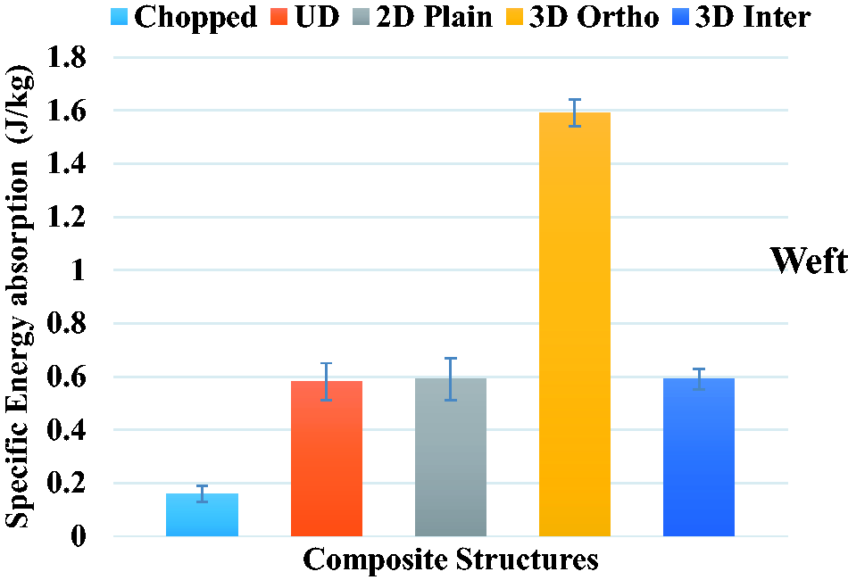
Specific energy absorption (bending) in the weft direction.
Influence of structural variation of 3D orthogonal structures on specific energy absorption under bending (3 point)
Figures 17 and 18 show the comparison of specific energy absorption for different 3D orthogonal composite structures in which binder yarn percentage was kept as 3%, 7%, 10%, and 13% and the samples were coded as 3S1B, 3S2B, 3S3B, and 3S4B respectively. It can be seen from the results that 3S1B composite exhibited the highest energy absorption and 3S4B exhibited the lowest in warp direction whereas 3S2B and 3S3B were found between the two. Whereas specific energy absorption of all 3D orthogonal composite structure found almost equal in weft direction with a variation of 3 to 4%. Therefore the specific energy absorption under flexural stress founds improvement with a reduction in binder thread content in 3D orthogonal composite in warp direction possibly because the stiffer the material lower will be the energy absorption. From results can be concluded that 3S1B exhibited higher energy absorption in both warp and weft direction compared to other composite structures which show it’s balanced and isotropic behavior and could be a potential material for leaf spring application. Other composite structures were found with a large variation in energy absorption in warp and weft direction.

Specific energy absorption (bending) in warp direction.

Specific energy absorption (bending) in weft direction.
Spring stiffness of different composite leaf spring
Figure 19 shows the comparison of spring stiffness of various composite leaf spring reinforced with different textile structures it is evident from the results that the spring stiffness of 3D Inter leaf spring found highest with a value of 21.75 N/mm whereas the stiffness of 3D Ortho reinforced composite leaf spring was 17.25 N/mm and approximately 63%, 6% and 14% higher compared to chopped, UD, and 2D respectively. Spring stiffness of 3D Inter and 3D Ortho was about 4 times and 2.5 times than that of chopped leaf spring. Spring stiffness of 3D Ortho structure was found comparable to UD and 2D with a difference of 10–15% and 3D inter with a variation of 20–25%. The higher spring stiffness of 3D composite leaf spring was attributed due to the presence of through-thickness reinforcement. This can be attributed from the above discussion that 3D Ortho can be a potential material for leaf spring due to its optimism stiffness and maximum energy compared to other composite leaf spring structures. 3D Inter being the highest stiffness and Chopped being the lowest stiffness is not suitable for such applications. Although UD and 2D leaf spring also have considerable stiffness and energy absorption and comparable to 3D Ortho, the problem of delamination may arise at a higher loading rate due to their laminated structure. It was also reported by Khatkar et al., Behera, and Dash [23,28] that UD and 2D composites have undergone a higher degree of delamination compared to 3D composites. This is in fact, the limitation of UD and 2D textile structural architecture in which it is impossible to produce higher thickness preforms of high areal density except for multi-layering by stitching or adhesive bonding. However, 3D weaving takes care of this limitation facilitating the production of integrated (due to Z binder reinforcement) heavy structure (multilayer) both in terms of thickness and areal density which prevent delamination [30

spring stiffness of different composite leaf spring.
Conclusion
Fabrication potential of 3D textile structural composites reinforced with different fiber architecture in the form of Chopped fiber, unidirectional (UD) tows, bidirectional plain woven (2D), and 3D woven orthogonal and interlock structures were analyzed in terms of tensile drilling performance, double bolted joint bearing failure response, specific flexural strain energy absorption and spring stiffness. Specific tensile strength composite reinforced with textile structure (UD, 2D and 3D ortho composites) found higher than conventional steel. Whereas specific strength of Chopped and 3D Inter (Warp) direction found lower than steel. Different composite structures have a unique response to the drilling of the hole. Chopped fiber composite was observed with fiber pullout sites near the edge of the hole. UD composite was noticed with delamination in the longitudinal direction; 2D composite has shown delamination due to poor interlaminar shear stress whereas 3D composite exhibited negligible delamination. The bearing strength of 2D woven composite was found highest followed by 3D, Chopped, and UD composite respectively. The strength of 3D orthogonal composites was found almost 20 to 22% higher than 3D interlock composite structures. Different bearing failure was noticed for different composite structures. UD composite exhibited complete shear out failure while chopped fiber reinforced composite failed due to tearing. 2D composite noticed with tearing and delamination failure. 3D orthogonal composite failed due to tearing in the warp direction and shear out in weft direction whereas 3D interlock failed due to tearing in both warp and weft direction. Specific energy absorption (SEA) was found highest in composite reinforced with the 3D orthogonal structure in both warp and weft direction along with optimum spring stiffness required for leaf spring application, whereas chopped fiber-reinforced composite structure gave the lowest SEA and spring stiffness. Specific energy absorption under flexural stress can also be enhanced by increasing stuffer thread density with proportionate reduction of binder thread content in 3D orthogonal composites without perceptible loss in spring stiffness. Hence 3D woven orthogonal structure reinforced composites can be considered as a potential material for automotive leaf spring application.
Supplemental Material
sj-pdf-1-jit-10.1177_1528083720974421 - Supplemental material for Influence of different textile structure reinforced composite leaf spring on their fabrication potential
Supplemental material, sj-pdf-1-jit-10.1177_1528083720974421 for Influence of different textile structure reinforced composite leaf spring on their fabrication potential by Vikas Khatkar and Bijoya Kumar Behera in Journal of Industrial Textiles
Footnotes
Declaration of conflicting interests
The author(s) declared no potential conflicts of interest with respect to the research, authorship, and/or publication of this article.
Funding
The author(s) received no financial support for the research, authorship, and/or publication of this article.
Supplemental material
Supplemental material for this article is available online.
References
Supplementary Material
Please find the following supplemental material available below.
For Open Access articles published under a Creative Commons License, all supplemental material carries the same license as the article it is associated with.
For non-Open Access articles published, all supplemental material carries a non-exclusive license, and permission requests for re-use of supplemental material or any part of supplemental material shall be sent directly to the copyright owner as specified in the copyright notice associated with the article.