
Abstract
In order to improve the red luminous properties of luminescent fibers, Sr2MgSi2O7:Eu2+, Dy3+ and light conversion agents were treated with silane (KH560), aluminate (DL-411-A), and aluminum zirconium coupling agents (LD-139-3) to prepare composite luminescent materials. And then they were added to a polyacrylonitrile (PAN) fiber-forming polymer and through wet spun to form composite red light-emitting fibers. The surface morphology, phase structure, and luminescence properties of the composite red light-emitting fibers were characterized by scanning electron microscopy, X-ray diffraction, fluorescence spectrometry, and afterglow brightness tester. Results showed that all of the three kinds of coupling agents influenced the red light of the luminescent fibers. The aluminate ester coupling agent had more effect than that of the other two coupling agents. After treatment with the aluminate coupling agent, the surface of the luminescent material became rough and adhered to the particles of light conversion agent. The intensity of the emission peak of the luminescent fibers at 470 nm decreased, and the emission peak intensity at 595 nm improved. The initial afterglow brightness and afterglow duration remained unchanged after 15 min of ultraviolet light excitation, as well as the color purity increased by approximately 1.6 times.
Luminescent fibers doped with rare-earth luminescent materials have excellent characteristics of high luminescent efficiency, long term afterglow, no harmful radiation, zero toxicity, and chemical stability [1]. The fibers can absorb ultraviolet or visible light for a few minutes, and can emit bright light in the dark for more than 10 hours [2–4]. Although rare-earth luminescent materials are used as raw materials for producing luminescent fibers recently, it was still suffered from some drawbacks and the luminous properties need to be improved. Also the emission color of most commercial rare-earth luminescent materials is around from the blue to the green, which limited the its application [5–7].
So in recent years, many researchers are focus on the red luminous materials, and most of these researchers consider composite luminescent red materials. XIA Yan introduced color conversion to generate red persistent luminescence by using SiO2/Sr2MgSi2O7:Eu2+, Dy3+ nanoparticles as blue persistent phosphor and ultrafine CaAlSiN3: Eu2+ as conversion phosphor [8]. CHEN Wenbo tuned the persistent luminescence spectra from blue to red through the transfer of radiative energy from CaAl2O4:Eu2+, Nd3+ to Y3Al5O12:Ce3+ [9]. Chen Zhi successfully fabricate the red luminous materials SrAl2O4:Eu2+, Dy3+/red-emitting fluorescent pigment by selecting TEOS as a silicon coating reagent via the sol-gel process [10]. Zhang Jishu the phosphor SiO2-Sr(4)A1(14)O(25):Eu2+, Dy3+/LCA (light conversion agent) was successfully prepared by sol-gel method, which can emit red light [11]. The afterglow duration and luminous intensity are reduced due to the influence of the SiO2 coating reagent. Zhu Yanan combined the light conversion agent with SrAl2O4:Eu2+, Dy3+ through siloxane, in which the light conversion agent can absorb green light (SrAl2O4:Eu2+, Dy3+) and then emit red light [12]. However, the stability of the materials need to be further improved. Nonetheless, previous work offered a new direction for research on warm color phosphors.
From study above, it is known that silane coupling agent is an intermediate combination agent whose alkoxy is hydrolyzed to form hydroxyl, which reacts with hydroxyl released by inorganic particles to form an –O–Si–R structure [13,14]. The epoxy group reacts with organic particles to combine the organic material with the inorganic material [15,16]. Also aluminate and aluminum zirconium coupling agents have similar mechanisms [17,18].
So in this study, we aimed to improve the coating effect of light conversion agent on Sr2MgSi2O7:Eu2+, Dy3+, enhancing the conversion efficiency of composite luminescent materials, and optimize the red light-emitting properties of luminescent fibers. Silane, aluminate, and aluminum zirconium coupling agents were used as combination to prepare composite luminescent materials. And then it was added into fiber-forming polymer (polyacrylonitrile (PAN)) through wet spun to form a composite red light-emitting fiber. And the effects of different coupling agents on the red light-emitting of luminescent fibers were investigated, which could provide a theoretical basis for the preparation of a red luminescent fiber with excellent luminescence properties.
Experimental
Preparation of Sr2MgSi2O7:Eu2+, Dy3+
Sr2MgSi2O7:Eu2+, Dy3+ was prepared by solid-state reaction by using SrCO3, MgO, Eu2O3, Dy2O3, and H3BO3 of analytical reagent grade as starting materials. SrCO3, MgO, Eu2O3, Dy2O3, and H3BO3 were accurately weighed according to the measurement ratios specified in Sr1.94MgSi2O7, 0.02Eu2+, 0.04Dy3+, and 0.1B3+, respectively. The measured ingredients were ground in a mortar, mixed for 30 min, and poured into a small beaker. The powders were dissolved in appropriate amounts of absolute ethanol and then ultrasonically dispersed for 30 min to obtain a homogeneous mixture. The hybrid was dried at 80 °C, slightly ground, placed into a small crucible, and heated in a high-temperature tube sintering furnace at 1400 °C for 4 h under reducing atmosphere. The sintered products were re-milled and sieved to obtain the desired samples.
Preparation of Sr2MgSi2O7:Eu2+, Dy3+/light conversion agent
Sr2MgSi2O7:Eu2+, Dy3+, light conversion agent, and C2H6O were added into a beaker, constantly stirred for 30 min, and added with 1.25% of the three coupling agents. The compounds were stirred and heated in a water bath at 40 °C–50°C for 30 min and then ultrasonically treated for 15 min (frequency: 100 kHz). The samples were stirred and heated at 60 °C–70°C until the alcohol evaporated. The samples were heated in an oven at 70 °C for 2 h. The products were milled and sieved to obtain the desired samples.
Sr2MgSi2O7:Eu2+, Dy3+, light conversion agent, and C2H6O were added into a beaker but without the addition of coupling agent to prepare the control sample. The other reaction conditions were consistent.
Preparation of luminescent fibers
PAN and DMSO were accurately weighed by a mass ratio of 19:100. The compounds were added into a beaker, stirred, and heated constantly in a water bath at 60 °C–70°C for 4 h to prepare a PAN fiber-forming polymer. Composite luminescent materials were added into the PAN fiber-forming polymer and wet spun to form luminescent fibers. The samples’ ratio of doped composite luminescent materials to the PAN fiber-forming polymer was 10:100. The coagulation bath was composed of an aqueous solution.
Characterization of red luminescent fibers
Scanning electron microscopy (SEM)
To investigate the distribution of Sr2MgSi2O7:Eu2+, Dy3+/light conversion agent in the luminescent fibers, we observed the cross section of luminous fibers by SEM (Quanta200, the Netherlands) at an accelerating voltage of 20 kV. All samples were dried and coated with gold before scanning.
X-ray diffraction (XRD)
X-ray diffraction (XRD) patterns were recorded on a D8 Advance X-ray diffractometer (Bruker AXS, Germany) with Cu Kα radiation (λ = 0.15406 nm) at a voltage of 40 kV and current of 30 mA. Samples were scanned over the range of diffraction angle 2θ = 5°–90°, with a scan speed of 0.2(°)/s at room temperature.
Luminous properties
The excitation and emission spectra of all the samples were measured by a fluorescence spectrophotometer (HITACHI650-60, Japan) at room temperature with a Xe flash lamp as an excitation source. The scanning speed was 120 nm/min. Chromaticity coordinates were tested, and chromaticity diagrams were obtained by a fluorescence spectrophotometer. Afterglow decay curves were tested using a PR-305 afterglow brightness tester (excitation illumination: 1000 lx, excitation time: 15 min) at room temperature. Before testing, samples were placed in the dark for more than 15 h to ensure complete attenuation of afterglow illumination.
Results and discussion
SEM analysis
Figure 1 shows the SEM images of the cross section of the luminescent fibers. Irregularly shaped particles of Sr2MgSi2O7:Eu2+, Dy3+ and light conversion agents were clearly visible, as shown in Figure 1(a) to (d). The particles of light conversion agent were smaller than those of Sr2MgSi2O7:Eu2+, Dy3+. Thus, light conversion agent could be coated on the surface of Sr2MgSi2O7:Eu2+, Dy3+ in the fabrication of composite luminescent materials, and the coating process of the light conversion agent to Sr2MgSi2O7:Eu2+, Dy3+ is illustrated in Figure 2. The coating effect varied under different coupling agents. From Figure 1(a) it can be seen that the when composite luminescent materials inside the luminescent fibers prepared without coupling agent, the surface of Sr2MgSi2O7:Eu2+, Dy3+ was relatively smooth, with a small amount of light conversion agent particles distributed on it. Figure 1(b) to (d) show the composite luminescent materials treated with silane, aluminate, and aluminum zirconium coupling agents. The surface of Sr2MgSi2O7:Eu2+, Dy3+ became coarse and more light conversion agent particles adhered to the phosphor compared with the Sr2MgSi2O7:Eu2+, Dy3+ particles, as shown in Figure 2.

Scanning electron microscopy of the cross section of the luminescent fibers containing different coupling agents. (a) Control group, (b) silane coupling agent, (c) aluminum zirconium coupling agent, (d) aluminate coupling agent.
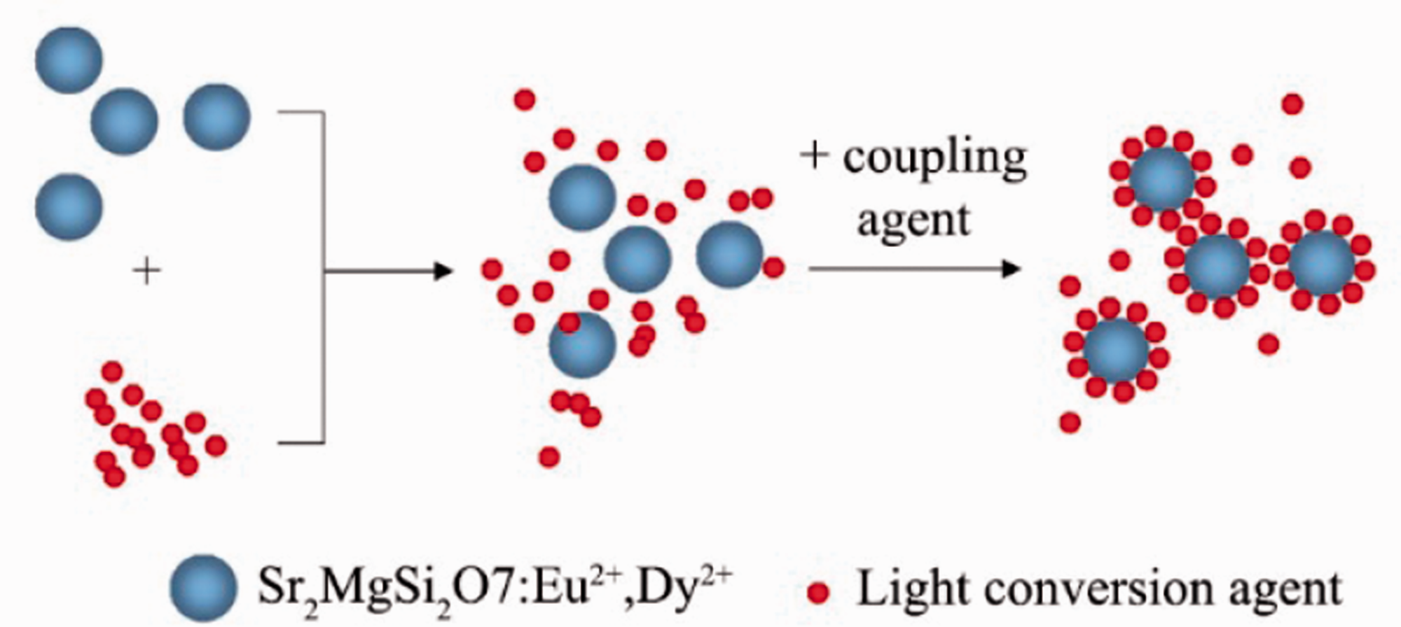
Coating process of light conversion agent to the Sr2MgSi2O7:Eu2+, Dy3+.
Ground state electrons of Eu2+ ions were promoted to excited states after excited by sunlight and ultraviolet light. The excited electrons were subsequently trapped by electron traps through the conduction band. the electrons trapped by shallow traps escape thermally via the conduction band and recombine with Eu2+, and then accompanied by blue long persistent luminescence. Light conversion agent is a small organic particle with many conjugated structures, which absorbed the blue light and promoted ground state electrons of conjugated structures to excited states, and red light appeared when the electrons returned to the ground state.
XRD analysis
XRD measurements were conducted to analyze the crystal structure matrix of luminescent fibers. As shown in Figure 3, pure monoclinic diffraction peaks of luminescent fibers were predominant in the XRD patterns, which were similar to that of commercial Sr2MgSi2O7:Eu2+, Dy2+ phosphors. The XRD patterns of the control group (luminescent fibers without coupling agent) exhibited sharp peaks at 17.5°, 28.5°, 30.7°, 35.8, and 43.5° 2θ, which were the characteristic diffraction peaks of Sr2MgSi2O7:Eu2+, Dy3+. This result indicated that the complex manufacturing process and doping of light conversion agents did not destroy the phase of Sr2MgSi2O7:Eu2+, Dy3+ in the fiber. The peak position and shape of the diffraction peak of luminescent fibers containing coupling agent were not changed, indicating that Sr2MgSi2O7:Eu2+, Dy3+ did not undergo any phase transformation after coupling agent treatment.

XRD patterns of the luminescent fibers containing different coupling agents and PDF card no. 75-1736.
Spectrum analysis
The excitation and emission spectra of the luminescent fibers made by composite luminescent materials treated with different coupling agents are shown in Figure 4. The results of Figure 4(a) illustrates that the excitation spectra of luminescent fibers presented a broad wavelength band, and the main excitation peak was still located at 365 nm whether the composite luminescent materials were treated with a coupling agent or not. The emission peak of luminescent fibers was located at 365 nm as shown in Figure 4(b). And the spectrum exhibited two emission bands located at 470 and 595 nm, which attributed to the typical 4f65d1–4f7 transition of Eu2+ (470 nm). The other peak at around 595 nm belonged to the emission of light conversion agents that absorbed blue light and released red light.

Excitation and emission spectrum of luminescent fibers containing different coupling agents. (a) Excitation spectrum, (b) emission spectrum.
After treatment with silane coupling agent, the emission peak showed a decrease in intensity at both 470 and 595 nm. This probably attributed to that the light-receiving area of both Sr2MgSi2O7:Eu2+, Dy2+ and light conversion agent. Also it is well known that the intensity decreased by 43% at 470 nm, which was more than the intensity decline by 20% at 595 nm. The emission peak intensity decreased by 27% at 470 nm and increased by 15% at 595 nm after treatment with the aluminate coupling agent. The reason was probably that aluminate coupling agent is an ester material, which has a good bond with the fiber substrate, making the composite material dispersed better in the fiber.
Decay of afterglow
Figure 5 shows the afterglow decay characteristics of luminescent fibers made by composite luminescent materials treated with different coupling agents. The afterglow initial brightness of the luminescent fibers is shown in Figure 6. As depicted in Figure 5, the afterglow decay of the luminescent fibers consisted of rapid attenuation in the first 500 s and slow decay thereafter. This process was determined by trap levels in different depths within the luminescent materials. The afterglow brightness of the luminescent fibers containing coupling agents declined significantly. This result was due to the light conversion agents that adhered to the surface of Sr2MgSi2O7:Eu2+, Dy3+, which absorbed and reflected a part of the exciting light energy. Furthermore, a part of the light energy emitted by Sr2MgSi2O7:Eu2+, Dy3+ was absorbed and reflected by the light conversion agent to some extent. Thus, both the afterglow decay process and afterglow initial brightness of the luminescent fibers containing coupling agents decreased [7]. Figure 6 illustrates that the afterglow initial brightness of the luminescent fibers containing silane, aluminate, and aluminum zirconium coupling agents were 0.04426, 0.05874, and 0.03713 cd/m2, respectively. The afterglow initial brightness of the luminescent fibers without a coupling agent was 0.06027 cd/m2. Thus, the three coupling agents have a certain effect on the combination of Sr2MgSi2O7:Eu2+, Dy3+ and light conversion agents, which may affect the afterglow brightness of the luminescent fibers.

Afterglow attenuation diagram of luminescent fibers containing different coupling agents.

Afterglow initial brightness of luminescent fibers containing different coupling agents. (a) Control group, (b) silane coupling agent, (c) aluminate coupling agent, (d) aluminum zirconium coupling agent.
Colorimetric analysis
Figure 7 shows the CIE 1931 chromaticity diagram for the luminescent fibers. The relevant color coordinates and color purity are summarized in Table 1. The color purity is the weighted average of the (x, y) coordinates relative to the coordinate of the illuminant and the coordinate of the dominant wavelength. Drawing straight lines from O (0.33, 0.33) through the color coordinates of samples intersect the spectral edge of the 1931 CIE chromatic diagram at point W. For example, luminous fibers are marked with c on the diagram, and its color purity can be calculated as follows:
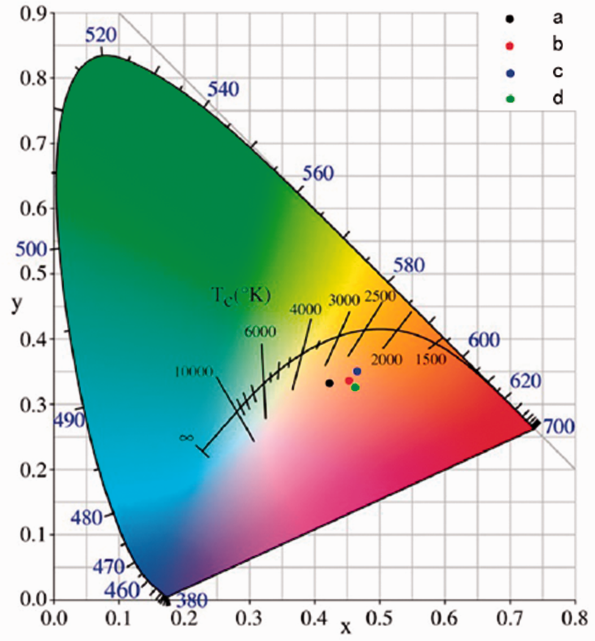
CIE chromaticity diagram of luminescent fibers containing different coupling agents. (a) Control group, (b) silane coupling agent, (c) aluminate coupling agent, (d) aluminum zirconium coupling agent.
Chromatic light color characteristics of samples.
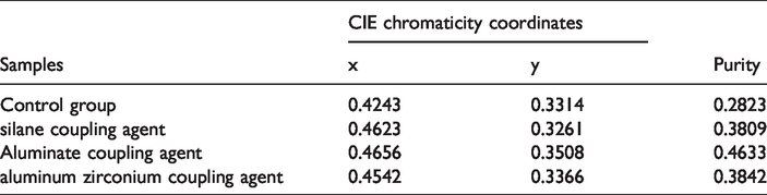
The luminescent fibers containing no coupling agent, silane, aluminate, and aluminum zirconium were a, b, c, and d, respectively, in the CIE 1931 chromaticity diagram. Figure 7 illustrates that the color coordinates of a, b, c, and d are located in the orange-red area. The emission color of luminescent fibers was increasingly close to red as the luminescent materials were treated with coupling agents, and fibers treated with aluminate coupling agent was better than that of the others. Table 1 shows that the color purity of a, b, c, and d was 0.2823, 0.3809, 0.4633, and 0.3842, respectively. The color purity of c was improved by 1.64 times compared with that of a. Thus, doping coupling agent can increase the effectiveness of a red shift in the fiber emission spectrum, and the effect of the aluminate coupling agent was better than that of the other two agents.
Conclusions
In this study, 1.25% silane, aluminate, and aluminum zirconium coupling agents were used in combination to prepare composite luminescent materials, which were added into PAN fiber-forming polymer and fabricated luminescent fiber through wet spun. The content of luminescent material was 10%, and the coagulation bath consisted of aqueous solution. The surface morphology, phase structure, and luminescence properties of the luminescent fibers were characterized, which had better properties compared to the previous research [11,19] and the results were summarized as follows: Morphological characterization demonstrated that the surface of Sr2MgSi2O7:Eu2+, Dy3+ treated with coupling agent became coarse and adhered to more light conversion agent particles compared with the control group (luminescent fibers containing no coupling agent). Crystal structure analysis demonstrated that the light conversion agent, coupling agents, and manufacturing process did not destroy the phase of Sr2MgSi2O7:Eu2+, Dy3+, which ensured its luminescent properties. From the spectral study, it is showed that under ultraviolet excitation, the emission peak intensity of luminescent fibers containing the aluminate coupling agent decreased by 27% at 470 nm and that of fibers containing the aluminate ester coupling agent increased by 15% at 595 nm. The CIE 1931 chromaticity diagram demonstrated that the color coordinates of samples were located in the orange-red area. The color purity of luminescent fibers containing the aluminate coupling agent increased by approximately 1.6 times.
The conclusion we get from above showed that the luminescent fibers had better luminescent properties with aluminate coupling agent by comparation. And also properties of luminescent fibers we made in this study were excellent compared to luminescent fiber fabricated with SrAl2O4:Eu2+, Dy3+/light conversion agent [11,19].
Footnotes
Declaration of conflicting interests
The author(s) declared no potential conflicts of interest with respect to the research, authorship, and/or publication of this article.
Funding
The author(s) disclosed receipt of the following financial support for the research, authorship, and/or publication of this article: This work was financially supported by Natural Science Foundation of Jiangsu Province (No. BK20171140), China Postdoctoral Science Foundation (No. 2018M630521).