
Abstract
Although membrane distillation (MD) technology has the outstanding advantages of almost 100% solute retention and mild operation conditions, its further development is limited by low permeate flux. In order to solve the problem, the improvement of membrane hydrophobicity becomes one of the effective solutions. In this study, a loose and porous hydrophobic zeolitic imidazolate frameworks-71 (ZIF-71)/polyvinylidene fluoride (PVDF) coating layer was composited on the outside surface of PVDF hollow fiber support membrane by the dilute solution coating to enhance membrane hydrophobicity. The prepared hollow fiber composite (HFC) membranes were employed to remove high concentration Congo red (CR) through VMD. The effects of different operation conditions including the dye concentration, feed temperature, vacuum pressure and feed flow rate on CR rejection and permeate water flux were investigated. In the variation range of operating conditions, all the CR rejection of the PVDF HFC membranes shows a slight change and remains above 99.9%. Under the optimal operation conditions including dye concentration 600 mg·L−1, vacuum pressure 31.325 kPa, feed temperature 60°C and feed flow rate 50 L·h−1, HFC membrane exhibit a permeate water flux of 13.15 kg·m−2·h−1. HFC membrane suffers dye fouling during the continuous dye filtration for 100 h. The fouling mechanism was proposed and a combined cleaning way including forward washing, back flushing and chemical desorption has been proved to be effective in recovering membrane water flux.
Introduction
As one of the important economic industries and international businesses in the world, the rapid development of textile industry also has some issues to be solved. Among them, textile dyeing wastewater, as the main source of environmental pollution in textile industry, has become one of the key industrial wastewater which needs harmless treatment in textile industry and environmental protection industry because of its high chemical oxygen demand (COD) and dyes content, complex water quality and large production. Various biological, physico-chemical technologies and their coupled methods have been widely used for the dyes removal. Dyes and various organic compounds in dyeing wastewater can be effectively degraded by various microorganisms such as brewery spent diatomite [1], white rot fungus [2], metaphyton [3], or by chemical oxidation process like ozonation [4] and photo-Fenton oxidation [5]. In addition, physical or chemical adsorbents such as activated carbon [6], carbon nanotubes [7], leaf-based adsorbents [8] have been also employed to remove dyes. Compared with these physico-chemical methods, the biological technology has been widely used in the treatment of dyeing wastewater due to its higher COD removal rate and lower sludge discharge [9]. Although the traditional methods described above have their advantages, the lower dye removal and desalination rates are the main drawback of these technologies. In recent years, as a new separation technology which can realize multi-component separation at the molecular level, membrane separation technology has been successfully applied in dye removal [7,10]. At present, ultrafiltration (UF) membrane and nanofiltration (NF) membrane are mostly used in dye remove due to their suitable pore size [11]. Chen [12] employed a novel positively NF membranes prepared through layer-by-layer (LBL) deposition of crosslinked polyelectrolytes to remove Congo red (CR) from aqueous solution. The rejection rates of CR and Brilliant green were 99.4% and 99.8%, respectively. Ding [13] prepared a UF composite membrane with regulated charge to remove CR and the rejection of CR can reach up to 93%.
As a typical anionic benzidine-based diazo dye, CR is often used in dyeing, food processing, papermaking and other fields [14,15]. And hence CR is also contained in the wastewater from these processes. The carcinogenic benzidine released from CR during the long-term exposure would increase the risk of cancer as per reported epidemiological studies and the poor biodegradability of CR also causes serious environmental pollution [16]. Many researchers are engaged in the research of CR removal by various methods including the chemical adsorption [17], coagulant [18], bioreactor [19] and membrane separation technology [20]. Compared with the traditional physical and chemical methods, the removal of CR dye by membrane separation technology has the advantages of energy saving and environmental protection, and is not limited by adsorption equilibrium. At present, most researches on CR removal are carried out by flat sheet UF membrane, adsorptive UF membrane or conductive UF membrane, such as polysulfone (PSF)/Polyvinyl alcohol (PVA) UF membrane [21], caramel/PSF adsorptive UF membrane [22], polyethersulfone (PES)/Chromolaena odorata (CO) adsorptive UF membrane [23] and electroless Ni plating PVDF UF membrane [24].
Compared with the pressure-driven membrane separation technologies such as UF, NF and even reverse osmosis (RO), membrane distillation (MD) can achieve nearly 100% dye removal rate and desalination rate without high-pressure operation. As the direct driving force of MD process, the temperature difference can be supplied by waste heat sources such as waste heat generated in power plant and other green energies such as solar energy and geothermal energy [25]. As the physical separator of MD process, hydrophobic separation membrane keeps hot feed liquid apart from cold permeate side. The hydrophobic property of the separation membrane makes the volatile components in the hot feed liquid vaporize on membrane surface. Driven by the steam pressure difference on both sides of the separation membrane, the vaporized steam passes through the micropores of the membrane and reaches the permeate side to be condensed and collected. In the whole MD process, the hydrophobic separation membrane only allows the vapor to pass through and prevents the liquid (water) from penetrating, so as to achieve efficient separation. DCMD is the simplest MD configuration, and is widely employed in desalination processes and concentration of aqueous solutions. The main drawback of this configuration is the heat lost by conduction because the evaporator and condenser surfaces are close leading to low effective driving force [26]. By contrast, the set-up procedure for VMD is complicated, mainly because of the vacuum and external condensers. However, condensation takes place outside the membrane module and hence the heat lost by conduction is negligible. This contributes to thin thermal and concentration boundary layers formed on the permeate side which is considered to be a great advantage for VMD [27].
Researches on the application of MD technology in dye removal have been reported and these reports mainly focus on three aspects: developing new hydrophobic separation membrane for MD [28], optimizing MD process [29] and coupling MD with other technologies such as photocatalytic technology [30,31]. These studies have achieved high dye removal rates, but most of them use flat sheet membranes and do not carry out further research on the recovery of membrane flux after dye fouling. Hollow fiber membrane has higher specific surface area and loading density than those of flat sheet membrane, and its special inner core can be directly used as the feed solution channel of MD process. In order to solve the problem of low permeate flux caused by low surface hydrophobicity of hollow fiber membrane for MD, various hydrophobic modification technologies have been developed, such as surface coating [32], surface grafting [33] and blending [34]. Among them, surface coating is a simple and effective method to prepare hydrophobic hollow fiber membrane by coating a layer of hydrophobic substance on the surface of hollow fiber substrate membrane. In the surface coating methods, the so-called solution coating is mostly carried out by dispersing hydrophobic additives such as silica [32] or dissolving hydrophobic polymers such as Teflon [35], Hyflon [36], polydimethylsiloxane (PDMS) [37] or polytrifluoropropylsiloxane [38] in the coating solution. This method needs to consider the effect of coating layer on the micropores of the substrate membrane. Therefore, the concentration of hydrophobic substances in most solution coatings is very low, generally less than 0.5 wt%. A new solution coating method (dilute solution coating method) is developed to obtain loose and porous coating by phase inversion of dilute polymer casting solution. The influence of this coating layer on the micropores of the substrate membrane and water vapor permeability can be ignored. At present, few researches are centered on the hydrophobic modification of hollow fiber membrane by dilute solution coating method. As the most commonly used hydrophobic separation membrane in MD, PVDF membrane has been modified by a variety of hydrophobic modification technologies [9,10,28]. However, there are few reports on the hydrophobic modification of PVDF membrane by dilute solution coating method.
As a promising functional substance, metal organic frameworks (MOFs) have many outstanding characteristics, such as high porosity and surface area, strong adsorption capacity, excellent catalytic and hydrogen storage characteristics [39]. Currently, MOFs have been successfully applied to water treatment, CO2 separation, hazardous materials removal and semiconductor [40]. As a subclass of MOFs, zeolitic imidazolate frameworks (ZIFs) having porous structure, excellent thermal and chemical stabilities as well as wide topological variety have been promising additives for the modification of separation membranes to obtain high-performance mixed matrix membranes (MMMs). Over the wide topological variety of ZIFs, ZIF-8 and ZIF-71 are the most commonly used functional additives for MMMs due to their excellent hydrophobicity and vapor adsorption capacity [41,42]. In contrast, ZIF-71 has more super-hydrophobic pore channels and larger cages. Therefore, the incorporation of ZIF-71 into hollow fiber membrane for MD can be expected to enhance the performance of hydrophobicity and vapor transfer rate [43]. At present, ZIFs have been successfully used in the modification of flat sheet membranes such as PDMS, polyimide and polyether-block-amide (PEBA). And these ZIFs modified membranes were applied in gas separation [44] and pervaporation [41,43]. However, the hydrophobic modification of PVDF hollow fiber membrane by ZIF-71 and the application in MD process for dye removal have not been reported.
In this study, CR was selected as the simulated dye. PVDF hollow fiber composite (HFC) membrane was prepared through the dilute coating of ZIF-71/PVDF layer. ZIF-71 was incorporated into the PVDF dilute solution and a porous coating layer was formed on membrane surface after the nonsolvent induced phase separation (NIPS). The prepared ZIF-71/PVDF HFC membrane was used to remove CR dye from aqueous solution. The possible ionic interaction between CR and the negatively charged PVDF membrane surface is expected to further improve the CR rejection of PVDF membrane. The effects of different operation conditions including the dye concentration, feed temperature, vacuum pressure and feed flow rate on dyes rejection and permeate water flux were well investigated. The fouling mechanism was proposed and a combined cleaning way including forward washing, back flushing and chemical desorption was developed to recover membrane water flux.
Materials and methods
Materials
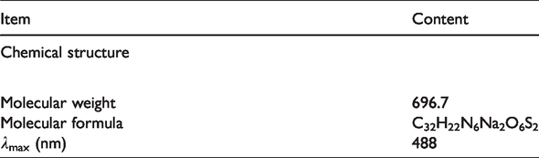
PVDF (FR-904) powder was obtained by Solvay Chemical Co., Ltd. (USA) and dried in a vacuum oven at 80°C for 12 h before use. Polyethylene glycol (PEG, Mw = 6,000 and 400), N, N-dimethylformamide (DMF) and CR were supplied by Tianjin Kemiou reagent Co., Ltd. (China). The chemical structure and other properties of CR dye are given in Table 1. Zinc acetate (ZA) and 4, 5-dichloroimidazole (DCIM) were obtained by Aladdin Industrial Corporation (Shanghai, China).
Chemical structure and characteristics of Congo red dye.
Synthesis of ZIF-71
ZIF-71 crystals were synthesized according to the method reported previously [43,45]. ZA (2.4 mmol) and DCIM (9.6 mmol) were dissolved in methanol (90 ml), respectively. The schematic diagram of the synthesis process of ZIF-71 was illustrated in Figure 1. ZA solution was rapidly poured into DCIM solution under continuous stirring. The mixed system would immediately become turbid. After 24 h of continuous stirring, the suspension solution was placed in a high-speed centrifuge at a rate of 8000 rpm to separate the suspension. Afterwards, the precipitates were washed with fresh methanol and centrifugation was continued to separate the precipitates. The cleaning and centrifuge processes were repeated twice. After freeze-drying for 24 h, the collected particles were sealed and preserved for use.

Schematic diagram of the synthesis process of ZIF-71.
Fabrication of PVDF hollow fiber membrane
PVDF hollow fiber membrane was fabricated through the typical dry-wet spinning technique as reported before [46–48]. The as-spun hollow fiber membrane was employed as the substrate for the subsequent dilute coating. The spinning dope was composed of PVDF (17 wt%), PEG-6,000 (6 wt%) and DMF (77 wt%). As a common pore-forming agent, PEG-6,000 with excellent water solubility can be well dissolved in coagulation bath (water) during phase inversion process, thus forming a porous membrane structure with high porosity. The coagulation bath and bore liquid were the water filtered by UF membrane at room temperature. The liquid flow was extruded through the central hole of spinneret under high pressure N2 and then immediately immersed in the coagulation bath for solidification after an air gap of 5 cm. The nascent hollow fiber membrane was immersed in pure water for 24 h and the pure water was changed every 6 h. Finally, PVDF hollow fiber membrane was immersed in fresh pure water for use.
Preparation of ZIF-71/PVDF hollow fiber composite membrane
ZIF-71/PVDF HFC membrane was prepared through the dilute coating method using PVDF hollow fiber membrane as the coating substrate. The dilute coating solution was composed of PVDF (5 wt%), ZIF-71, PEG-400 (33 wt%) and DMF. The hollow fiber membrane sealed at both ends was immersed in the coating solution for 10 s. Then, the membrane was taken out and immediately immersed in pure water for 24 h. Pure water was changed every 6 h for the complete removal of residue solvent in hollow fiber membrane. The obtained ZIF-71/PVDF hollow fiber composite membrane was preserved in 30 vol% glycerin aqueous solution for 24 h and dried at room temperature for the module fabrication. Two ends of the hollow fiber membranes were sealed with epoxy resin and then cut to fabricate the membrane modules. In order to compare the effect of different ZIF-71 content on the dye removal properties of the HFC membranes, HFC membranes with 0, 0.5, 1 and 2 wt% ZIF-71 (corresponding DMF contents of 62, 61.5, 61 and 60 wt%) in the coating solution were prepared.
Characterization of membrane structure and morphology
The surface and cross sectional morphologies of different hollow fiber membranes are observed by the Scanning electron microscopy (SEM, FEI Quanta 250, USA). Membrane samples were frozen in liquid nitrogen, fractured and then sputtered with gold prior to SEM observation. Fiber outer/inner diameters were obtained by the SEM images. The pore size distribution of PVDF hollow fiber composite membrane was obtained by analyzing at least 100 pores in the SEM image using Image J software (NIH). The surface SEM images of the as-synthesized ZIF-71 crystals were also observed by SEM. And the crystal diameter distribution was obtained by analyzing at least 100 crystals in the SEM image using Image J software (NIH). The mean pore size and maximum pore size of HFC membrane were measured using a capillary flow porometry (3H-2000 PB, Beishide Instrument, China). Membrane samples were wetted in a fluid (Porwick, proprietary product of PMI, surface tension of 18 dyn/cm) and sealed in a chamber for the measurement. As the pressure increased, the inert gas (nitrogen) intruded into the micropores with the largest diameter and gradually filled the micropores in membrane samples. Data were automatically recorded. The porosity of PVDF HFC membrane was obtained through the weight difference method and calculated by equation (1). For each membrane sample, five measurements were carried out and an average value was obtained.
The hydrophobicity of membrane outer surface was examined through the dynamic water contact angle (WCA) on a Kruss Instrument (CM3250-DS3210, Germany) at ambient temperature. Three locations were chosen to measure the contact angles and three measurements were carried out for each membrane sample. Their average value was obtained to minimize the experimental error. Liquid entry pressure (LEP) is an important MD parameter for evaluating the penetration capacity of the aqueous solution into membrane pores. The LEP data of different PVDF hollow fiber membranes are examined through the method of gas compression [49].
Dye removal by VMD
Dye removal experiment
The dye solution containing a certain concentration of anionic dyes of CR was employed as the feed solution in VMD experiment to investigate the dye removal by ZIF-71/PVDF HFC membrane. The effects of different operation conditions including feed temperature, dye concentration in feed solution, vacuum pressure and feed flow rate on dye removal rate were studied. Hollow fiber membrane modules were installed on the VMD equipment as illustrated in Figure 2. The hot dye solution was filled in the shell side of ZIF-71/PVDF HFC membrane modules and circulated by the peristaltic pump. The vapors produced on the interface of membrane micropores and feed solution would pass through membrane micropores driven by the vacuum pressure at membrane permeate side and be condensed by the stainless steel spring tube cooled by liquid nitrogen. The condensed droplets were collected in a beaker on the balance and weighed.

Schematic diagram of dye removal by ZIF-71/PVDF hollow fiber membrane through vacuum membrane distillation.
Membrane permeate water flux (Jw) is defined as the mass of water passing through the membrane per unit area in a unit time and can be calculated by the following equation.
The dye rejection (R) of hollow fiber membrane can be obtained by equation (3).
Mechanism of MD process
Three mechanisms including Knudsen diffusion, molecular diffusion and Poiseuille flow transition are empirically used to simulate MD process and the water flux across the membrane (Jw) can be expressed by equation (4) [51].


In MD process, mass transfer resistance is the key factor affecting permeate water flux. The overall mass transfer resistance (1/k) can be obtained as follows [54].
Although MD technology has many advantages over other membrane separation technologies, its wide application is limited by its low permeate water flux. The effective solution is to maximize of the mass transfer and energy efficiency through the optimization of the operation conditions [55]. Therefore, the effects of operation conditions including feed temperature and dye concentration, vacuum pressure and feed flow rate on dye removal performance of different hollow fiber membranes during the VMD process were well investigated.
Membrane cleaning
After a certain time of dye filtration, membrane cleaning is needed for the recovery of water flux. A combined cleaning methods are selected in sequence including forward washing, back flushing and chemical desorption. The fouled membrane was first rinsed with pure water for 30 min. Afterwards, back flushing for another 30 min was employed using pure water as the washing solution. Finally, back flushing for another 1 h was carried out using 0.05 mol·L−1 sodium hydroxide solution as the chemical desorption solution [56]. In order to compare the variation of water flux in different stages more clearly, the normalized flux (Fn) which is defined as the ratio of real-time water flux to initial water flux was used and calculated by the following equation [57].
Results and discussion
Morphology of ZIF-71 crystals
Figure 3(a) and (b) show the surface SEM images and the diameter distribution of the as-synthesized ZIF-71 crystals. It can be observed from Figure 3(a) that ZIF-71 crystal has a similar polygonal structure as previously reported [41,43,44,58]. The particle diameter of the ZIF-71 is mainly distributed between 0.5–1.0 µm as shown in Figure 3(b). The size of ZIF-71 prepared in this study is larger than those of ZIF-71 reported previously (most of them are between 100-700 nm). This is due to the aggregation of ZIF-71 crystals caused by strong Zn-DCIM-Zn bond cooperation during drying process [44,59]. It should be pointed out that ZIF-71 aggregates can be well dispersed in relatively weak polar solvents [44], such as DMF used in the preparation of casting solution.
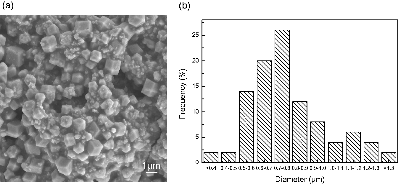
Surface SEM images (×5.0 K) (a) and the diameter distribution (b) of ZIF-71 crystals.
Morphology of hollow fiber membranes
Figure 4 shows the macroscopic appearance of the ZIF-71/PVDF hollow fiber composite membranes. It should be pointed out that there is no difference between the hollow fiber composite membrane and the PVDF support membrane (which is not shown here) from the macroscopic morphology.

The macroscopic appearance of ZIF-71/PVDF hollow fiber composite membranes.
The cross-sectional and surface morphology of different PVDF hollow fiber membranes were observed by SEM and the corresponding SEM images are shown in Figures 5 and 6, respectively. The original PVDF hollow fiber membrane (i.e. the PVDF support membrane) exhibits a typical structure with the double finger-like pores and large voids as shown in Figure 5(a). The porous structure provides more steam transfer channels, which can reduce the vapor transfer resistance in MD process. In addition, the porous structure is conducive to maintaining a low thermal conductivity of the hollow fiber membrane, thereby reducing the heat loss and improving the heat transfer efficiency during the MD process [60,61]. Compared with the relatively smooth outside surface of PVDF hollow fiber support membrane, the outside surface of PVDF composite membrane becomes rough and is densely covered with lots of bulges. This rough surface is formed by the PVDF dilute solution coating. Compared with the convectional concentrated polymer solution, the PVDF dilute solution which has a very low PVDF concentration (5 wt%) in the spinning dope can form a loose and porous coating layer after the NIPS (as shown in Figure 6(c)). This is beneficial to the improvement of membrane surface hydrophobicity and MD permeability.

Cross-sectional SEM images of different PVDF hollow fiber membranes. (a/b) riginal PVDF hollow fiber membrane and (c/d) ZIF-71/PVDF HFC membrane (a/c) ×60; (b/d) ×3.0 k.

Surface SEM images of different PVDF hollow fiber membranes. (a/b) original PVDF hollow fiber membrane and (c/d) PVDF hollow fiber composite membrane (a/c) ×1.0 k; (b/d) ×5.0 K.
The appearance of ZIF-71 in the PVDF coating layer on the composite membrane surface can be obvious observed through the magnified SEM picture as shown in Figure 6(d). It can be seen that the polygon cubic ZIF-71 crystals are tightly wrapped by PVDF coating matrix. Compared with traditional inorganic particles, ZIF-71 was composed of central metal elements (zinc) and organic chains connected with them. Water molecules can hardly penetrate in the bulk phase and be further adsorbed in the hydrophobic cage of ZIF-71 [41,43,44]. This special structure of metal organic frameworks can greatly increase the specific hydrophobic surface, thereby increasing the water permeate flux of membrane distillation. The porous cavity and its organic linkers in ZIF-71 crystals greatly enhance the compatibility and adhesion with PVDF coating matrix which would be beneficial to the long-term stability of ZIF-71/PVDF hollow fiber composite membrane in the MD process. The WCA and LEP of different PVDF hollow fiber membranes were examined. And both the WCA and LEP have obvious improvement from 94.5° and 168 kPa to 134° and 220 kPa, respectively. As described previously [41–43], ZIF-71 has a superhydrophobic framework in nature. The improvement of membrane surface hydrophobicity after the addition of ZIF-71 is mainly due to the emergence of these superhydrophobic ZIF-71 crystals on PVDF membrane surface. These results indicate the surface hydrophobicity and wetting resistance are enhanced after the coating of ZIF-71/PVDF layer which would favor the high dye removal rate and long-term stability of MD performance.
The pore size distribution of ZIF-71/PVDF HFC membrane was also measured by Image J software (NIH) and the results are shown in Figure 7. It can be seen that the pore size is mainly distributed between 0.4-0.9 μm. The pore size of more than 78% of the pores is larger than 0.5 μm. According to the previous reports, membrane pore size for MD should be less than 0.5 μm which can prevent the membrane pore wetting and maintain the stability of MD separation performance [45,46]. This means that the ZIFs/PVDF coating layer with larger pore size will not produce additional resistance to MD mass transfer process under it. In addition, the average and maximum pore sizes of HFC membrane were measured by a capillary flow porometry and the corresponding data as well as the parameter of membrane parameters are listed in Table 2. It should be pointed out that the average pore size and the maximum pore size listed in Table 2 are obtained by gradually increasing the pressure, which largely reflects the pore size of the substrate membrane. It can be seen that both the average and maximum pore sizes are less than 0.5 μm, which will be conducive to the long-term stability of MD separation performance.

Pore size distribution of ZIF-71/PVDF HFC membrane.
Parameters of PVDF HFC membrane and its module.

Effects of dye concentration on dye removal performance during VMD process
Figure 8 presents the variations of permeate water flux and CR rejection of PVDF HFC membrane as a function of dye concentration in feed solution. It can be seen from Figure 8 that the permeate water flux of PVDF HFC membrane shows a slight decrease with the increase of dye concentration. The corresponding flux reduction is only 5.5% when the dye concentration increases from 100 to 600 mg·L−1. The increase of dye concentration has little effect on the geometry and structural parameter of PVDF hollow fiber membranes. Thus, the slight decrease of permeate water flux is mainly attributed to the relatively weak driving force according to equation (5) [62]. As the number of dye molecules in feed solution increases, the solute concentration in the boundary layer gradually increases. This induces an increasingly serious concentration polarization [63,64]. It can also be seen from the calculated mass transfer resistance as listed in Table S2 that the overall mass transfer resistance gradually increases with the increase of dye concentration in the feed solution. The driving force weakens along with the slight decrease of membrane permeate flux as shown in Figure 8. In contrast, the CR rejection of PVDF HFC membrane remains basically constant and the corresponding data are above 99.9%. These results indicate that the rejection of non-volatile solute by PVDF hollow fiber membranes during the VMD process has no selectivity and the dye concentration has no remarkable influence on the permeate flux and dye rejection.

Variation of permeate water flux and CR rejection of ZIF-71/PVDF HFC membrane with different dye concentration in feed solution (feed temperature 60 °C; vacuum pressure 31.325 kPa; feed flow rate 50 L.h−1).
Effects of feed temperature on dye removal performance during VMD process
Figure 9 shows the variations of permeate water flux and CR rejection of PVDF hollow fiber composite membrane with feed temperature. It can be seen from Figure 9 that the CR rejection of the modified PVDF HFC membrane keeps above 99.9% when the feed temperature increases from 30 to 80°C. Compared with the change of CR rejection, the variation of permeate water flux with feed temperature is more obvious as shown in Figure 9. With the increase of feed temperature, the permeate water flux of the modified PVDF HFC membrane gradually increases from 9.76 to 16.68 kg·m−2·h−1. It basically exhibits an exponential variation. Previous reports obtained the similar relationship between permeate water flux and feed temperature during the VMD process [65,66].

Variations of permeate water flux and CR rejection of ZIF-71/PVDF HFC membrane with feed temperature (dye concentration 600 mg.L−1; vacuum pressure 31.325 kPa; feed flow rate 50 L.h−1).
As the driving force of mass transfer in MD process, vapor pressure is proportional to the temperature difference [67]. Thus, a large temperature difference will result in a large vapor pressure difference and a high permeate flux, as listed in equation (5). It can also be confirmed from the resistance calculation results as listed in Table S3 that the overall mass transfer resistance shows an obvious decrease with the increase of the feed temperature. In contrast, the dye rejection maintains at a high level during the whole process, regardless of the temperature difference. According to equation (7), the transmembrane vapor pressure would exponentially increase as a function of the feed temperature, thereby increasing the driving force of mass transfer during the MD process. In addition, a higher feed temperature results in a lower viscosity of feed solution and thus the boundary layer thickness near the feed-membrane interface will become thinner [68]. This contributes to a low boundary layer resistance (1/kL) which is beneficial to the decrease of MD mass transfer resistance according to equation (8) and the increase of permeate water flux [69].
Effects of vacuum pressure on dye removal performance during VMD process
The variations of the dye rejection and permeate flux of PVDF hollow fiber composite membranes with the vacuum pressure are shown in Figure 10. Obviously, the permeate water flux of PVDF HFC membrane shows a decrease with the increase of vacuum pressure from 6.325 kPa to 91.325 kPa. This is due to the fact that the important driving force in VMD process is the vapor pressure difference across both sides of the membrane pores. Vacuum pressure on the permeate side significantly influences the permeate water flux and the VMD operation process. The vapors can be taken away instantly under a lower downstream pressure once the vapor-liquid interface at each pore entrance is formed [70]. Moreover, low vacuum pressure can effectively prevent the formation of the boundary layer on the permeate side and hence enhance the vapor mass transfer as well as the permeate water flux [65]. The increase of vapor pressure difference is beneficial to the enhancement of mass transfer process, which can also be confirmed by the gradual decrease of mass transfer resistance as listed in Table S4. These results are consistent with equation (5) and the previous reports [71,72]. It should be noted that the partial wetting of membrane micropores might be caused under a very high vacuum pressure. Because the vapors can not be discharged from the membrane pore promptly, a small amount of water vapors condenses and then causes partial wetting of membrane pores, which leads to the further decrease of permeate water flux [73].

Variations of permeate water flux and CR rejection of ZIF-71/PVDF HFC membrane with vacuum pressure (dye concentration 600 mg.L−1; feed temperature 60 °C; feed flow rate 50 L.h−1).
Effects of feed flow rate on dye removal performance during VMD process
The feed flow rate has an important influence on the solute distribution and the feed flow state near hollow fiber membrane surface. Figure 11 shows the variations of permeate water flux and CR rejection of PVDF HFC membrane with feed flow rate. It can be seen that the permeate water flux is enhanced from 8.71 to 14.05 kg·m−2·h−1 with the increase of feed flow rate. The shear strength will be enhanced with the increase of feed flow rate and the laminar flow with low velocity would be changed into turbulent flow with fast velocity. This can effectively alleviate the concentration and temperature polarization caused by solute accumulation in the boundary layer near membrane surface [73,74]. With the thinning or even disappearance of the boundary layer region, the mass transfer resistance can be greatly reduced meanwhile the heat transfer efficiency will be improved [75]. According to equations (7) and (8), the feed flow rate directly affects the vapor pressure at the permeate side and MD mass transfer resistance. With the increase of the feed flow rate, the mass transfer resistance exhibits an obvious decrease which accelerates the MD mass transfer process. Consequently, the permeate water flux exhibits a gradual increase with the acceleration of feed flow rate. A linear increase relationship between membrane permeate water flux and feed flow rate was well obtained in previous reports on the desalination of seawater [65], the treatment of bentazon herbicide solutions [70] and the recovery of ammonia from biogas slurry [72]. It is also reported that the relationship between the permeate flux and feed flow rate can be a nonlinear increase during the desalination process and the treatment of saline wastewater produced by natural gas exploitation [73]. Similarly, a nonlinear increase relationship between the permeate flux of PVDF HCF membrane and feed flow rate is obtained as shown in Figure 11. With the increase of the feed flow rate, the thickness of the boundary layer on the membrane surface has become very thin and further increase of the flow rate would not greatly increase the membrane water flux.
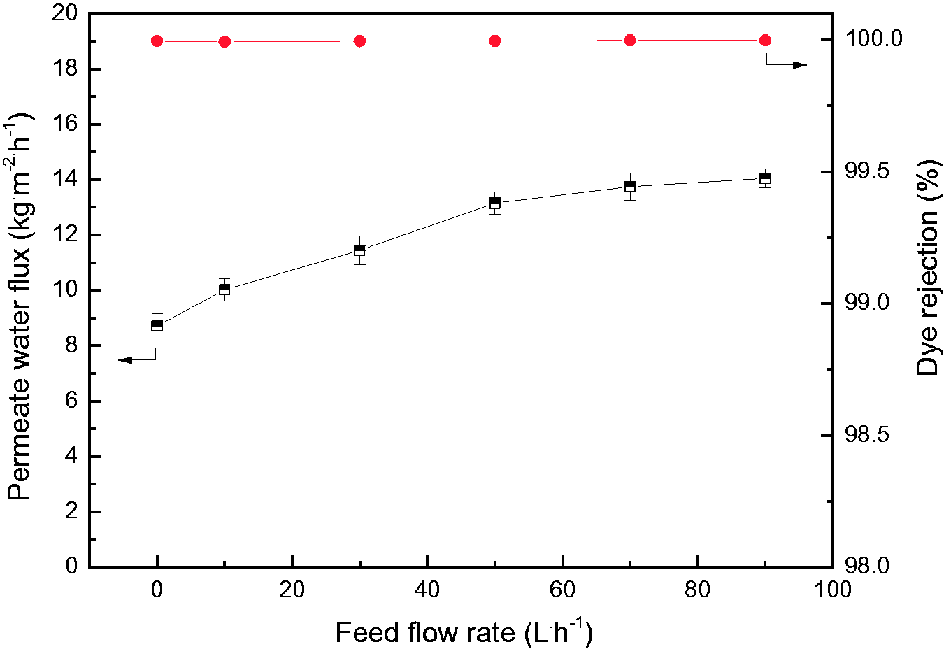
Variations of permeate water flux and CR rejection of ZIF-71/PVDF HFC with feed flow rate (dye concentration 600 mg.L−1; feed temperature 60 °C; vacuum pressure 31.325 kPa).
Comprehensive analysis of four operation conditions
Through the above analysis of the effects of the four operation conditions on the dye removal performance, it can be obtained that the dye rejection rate is basically above 99.0% and the changes of permeate water flux is more obvious. Therefore, in order to better compare the effects of four operation conditions on the decolorization performance of different hollow fiber membrane, the variations of normalized water flux of PVDF hollow fiber composite membrane with different VMD operation conditions were draw in Figure 12.

Variations of normalized water flux of ZIF-71/PVDF HFC with different operation conditions (a) dye concentration and vacuum pressure; (b) feed flow rate and feed temperature.
As shown in Figure 12(a), with the changes of dye concentration and vacuum pressure, the normalized water flux of PVDF HFC membrane varied from 100% to 94.5% and 242.6%, respectively. It can be seen from Figure 12(b) that the normalized water flux increases from 100% initially to 161.3% and 170.9% with the changes of feed flow rate and feed temperature, respectively. Obviously, in the range of experimental parameters, the sequence of influence on membrane permeate flux is vacuum pressure >feed temperature >feed flow rate >dye concentration. The normalized water flux increases rapidly when the vacuum pressure is less than 50 kPa. When the flow rate of feed liquid exceeds 50 L·h−1, the flux increase trend slows down. Moreover, the normalized water flux decreases rapidly when the dye concentration is between 300 and 500 mg·L−1, but the overall influence of the feed concentration is only within 10%. Therefore, in the actual operation process, the appropriate operating conditions for the CR removal can be selected combined with the above comprehensive analysis.
Various anionic dyes were selected to further test their removal properties in VMD process and the rejection results are listed in Table 3. It can be seen that under the optimized VMD operation conditions, the rejection of these ten anionic dyes by PVDF HFC membrane are all above 99.9% and the permeate water flux is between 12-14 L·m−2.h−1, which is similar to the CR test results in this study. This further indicates that the PVDF composite membrane has a good removal of anionic dyes.
The VMD performance of various anionic dyes by PVDF HFC membrane (VMD operation conditions: dye concentration (600 mg·L−1), vacuum pressure 31.325 kPa, feed temperature 60 °C and feed flow rate 50 L·h−1).

Comparison of dye removal by different PVDF hollow fiber membranes
Through the above comprehensive analysis, the operation conditions including dye concentration 600 mg·L−1, vacuum pressure 31.325 kPa, feed temperature 60°C and feed flow rate 50 L·h−1 were selected as the optimal VMD process. Under the above optimized VMD operating conditions, the effect of ZIF-71 content in coating solution on the CR removal performance of different PVDF HFC membranes was investigated and the results are shown in Figure S1. It can be seen that with the increasing of ZIF-71 content in coating solution the permeate water flux initially increases rapidly and gradually levels off when ZIF-71 content reaches 2 wt%. The CR rejection of all PVDF HFC membranes can be maintained above 99.9%. These results suggest that PVDF HFC membrane with the incorporation of 1 wt% ZIF-71 in the coating solution has the best CR removal performance. In addition, the CR removal property of the original PVDF hollow fiber (HF) membrane, i.e. PVDF support membrane, was also tested and compared with PVDF HFC membranes. The CR removal rate and permeate water flux of PVDF HF membrane are 99.3% and 8.36 L·m−2.h−1, respectively, which are obviously worse than those of the PVDF HFC membranes.
This enhancement of vapor mass transfer is ascribed to the improvement of the hydrophobicity and roughness of membrane surface. Commonly, membrane with high hydrophobicity can effectively prevent the entry of liquid into membrane pores and the nonwetting phenomenon [76]. The increase of membrane surface roughness can enhance the turbulence near membrane surface and make the boundary layer thinner, thus reducing the concentration and temperature difference polarization and improving the efficiency of mass transfer and heat transfer [77]. Previous literatures have reported that the introduction of particles with high thermal resistance such as calcium carbonate nano-particles [78], graphene oxide [79,80] and cloisite [81] can reduce the thermal conductivity of separation membrane materials. Similarly, the introduction of ZIFs with excellent thermal stability can further reduce the thermal conductivity of the PVDF hollow fiber composite membrane and hence improve the heat transfer efficiency during the VMD process. All of these are beneficial to the improvement of the final water flux of the composite membrane. The agglomeration phenomenon caused by the introduction of high content ZIF-71 would cause the VMD water flux to level off. Similar results have been obtained in the previous literatures on nanocomposite membranes with functional additives such as graphene oxide [79,80]. It should be pointed out that ZIF-71/PVDF HFC membrane mentioned in this study refers to the HFC membrane prepared with 1 wt% ZIF-71 in the coating solution unless otherwise specified.
Table S1 lists the performance of dye removal by various MD processes reported in previous literatures. As listed in Table S1, different MD processes and separation membranes were used to remove different dyes. Tetraethyl orthosilicate (TEOS) crosslinked polystyrene (PSt) flat sheet membrane was used in DCMD process to remove 1 g·L−1 CR. The CR rejection and permeate water flux are 99% and 0.0041 kg·m−2.h−1, which are much lower than the CR rejection of above 99.9% and the water flux of 13.15 kg·m−2.h−1 obtained in this study. In contrast, most of the dye removal rate in Table S1 is below 99.9%, which is lower than the CR removal rate in this study. The water fluxes of dye removal by different hollow fiber membranes as listed in Table S1 are 4.14, 12.5 and 36.82 kg·m−2.h−1, respectively. The water flux of 13.15 kg·m−2.h−1 of the ZIFs/PVDF HFC membrane in this study is at a relatively high level. It should be pointed out that the water flux of 36.82 kg·m−2.h−1 reported in previous literature is obtained at very high temperature (90°C) as listed in Table S1. The water flux of the ZIFs/PVDF HFC membrane was obtained at a lower temperature of 60°C.
Long-term stability of membrane performance during VMD process
Figure 13 shows the variation of normalized water flux of PVDF HFC membrane with operation time. It can be seen that after continuous filtration of 100 h membrane normalized flux declines to 88%. This indicates that PVDF HFC membrane suffers dye fouling. The interaction mechanism between CR molecules and ZIF-71/PVDF HFC membrane surface is shown in Figure 14. The affinity between the negatively charged CR molecules and the negatively charged PVDF membrane surface is weak, but a small amount of dye molecules in the dye solution matrix will accumulate physically on the membrane surface with the prolongation of dye filtration time. On the other hand, the introduction of ZIF-71 particles with strong adsorption characteristics on the membrane surface also makes some dye molecules adsorb on and inside the metal organic framework. Therefore, three membrane cleaning methods are selected in sequence, i.e. forward washing, back flushing and chemical desorption.
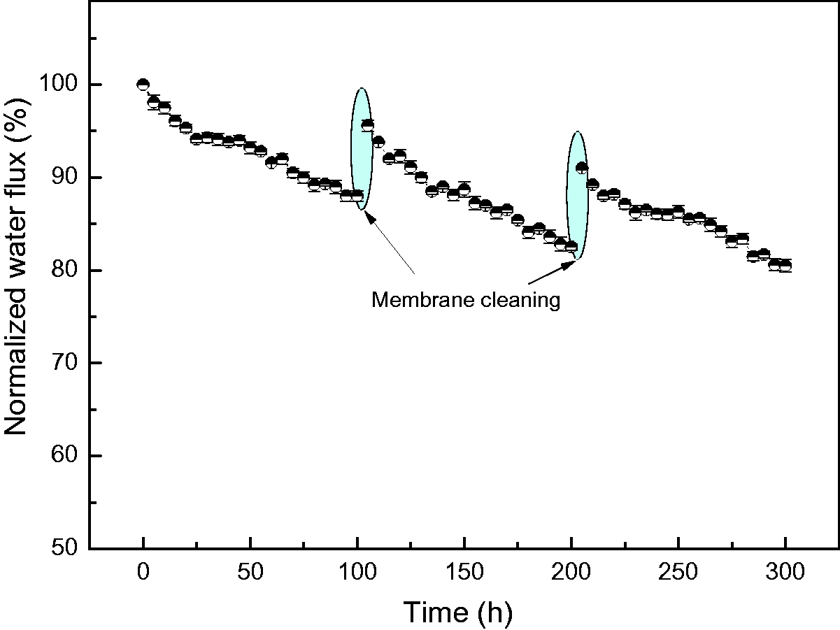
Variation of normalized water flux of ZIF-71/PVDF HFC with operation time (dye concentration 600 mg.L−1; feed temperature 60°C; vacuum pressure 31.325 kPa; feed flow rate 50 L.h−1).
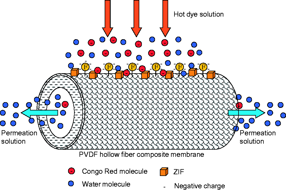
Schematic diagram of the interaction mechanism between CR molecules and ZIF-71/PVDF HFC membrane surface during the MD process.
It can be seen from Figure 13 that after this series of membrane cleaning process, the normalized flux of PVDF HFC membrane can be recovered to 95.6%. Similarly, after the second dye filtration, these three cleaning methods were also employed to clean PVDF HFC membrane and the data of normalized flux is up to 91%. It should be noted that the CR rejection during the whole VMD process remains above 99.9% although HFC membrane was fouled to some extent. Figure 15 illustrates the mechanism of this combined cleaning. The forward washing can effectively peel off the dye molecular layer, i.e. cake layer as illustrated in Figure 15(a), on the membrane surface formed after a long-term MD operation. A part of the dye molecules entering the membrane micropores can be removed by back flushing as shown in Figure 15(b). Besides, dye molecules adsorbed on the membrane surface and the wall of membrane micropore can be desorbed by chemical cleaning as presented in Figure 15(c).

Schematic diagram of the mechanism of combined cleaning for the fouled ZIF-71/PVDF HFC membrane.
The operation time has been further extended to investigate the possible variation of membrane normalized water flux and the results are shown in Figure S2. It can be seen that the combined cleaning can effectively recover MD water flux after three filtration cycles, and the value is basically maintained at about 90%. ZIFs/PVDF HFC membrane exhibits similar fouling phenomenon during each filtration cycle and the normalized water flux decreases to about 80% after each filtration cycle. The MD separation efficiency is reduced due to the low permeate water flux for a long operation time. Therefore, in practical application, when the normalized water flux of ZIFs/PVDF HFC membrane drops to about 80%, it is recommended to carry out membrane cleaning in time to quickly recover the membrane water flux.
Conclusions
PVDF hollow fiber membrane was hydrophobically modified through the incorporation of ZIF-71 on membrane surface by the dilute solution coating method. The modified PVDF HFC membrane has no selectivity for the rejection of Congo red and exhibits a high removal rate for Congo red above 99.9%. The increase of feed temperature and the reduction of vacuum pressure can enhance the driving force of VMD and hence increase the water flux. The changes of feed flow rate and CR concentration has an effect on the boundary layer of the membrane surface, thus affecting the concentration polarization and temperature difference polarization. The incorporation of ZIFs with high thermal resistance is also conducive to the improvement of heat transfer efficiency and membrane water flux. The combined cleaning method including forward washing, back flushing and chemical desorption can effectively remove the dye molecules accumulated on the membrane surface and adsorbed in ZIF-71, so as to efficiently recover the membrane water flux. It is confirmed that the ZIF-71/PVDF hollow fiber composite membrane can effectively remove Congo red under the optimized VMD process conditions. ZIF-71/PVDF hollow fiber composite membrane is a promising candidate for other dyes of pollutants removal by VMD process.
Supplemental Material
sj-pdf-1-jit-10.1177_1528083720967075 - Supplemental material for Removal of high concentration Congo red by hydrophobic PVDF hollow fiber composite membrane coated with a loose and porous ZIF-71PVDF layer through vacuum membrane distillation
Supplemental material, sj-pdf-1-jit-10.1177_1528083720967075 for Removal of high concentration Congo red by hydrophobic PVDF hollow fiber composite membrane coated with a loose and porous ZIF-71PVDF layer through vacuum membrane distillation by Hongbin Li, Wenying Shi, Qiyun Du, Shoufa Huang, Haixia Zhang, Rong Zhou and Xiaohong Qin in Journal of Industrial Textiles
Footnotes
Declaration of conflicting interests
The author(s) declared no potential conflicts of interest with respect to the research, authorship, and/or publication of this article.
Funding
The author(s) disclosed receipt of the following financial support for the research, authorship, and/or publication of this article: The authors gratefully acknowledge the funding for the Project supported by the Program for Henan Science and Technology Development (No. 202102210031), Training plan for Young Scholar in Colleges and Universities in Henan Province (No. 2018GGJS151), Research and Cultivation Fund Project of Henan University of Engineering (PYXM202013) and the Central Plains Thousand People Program-Top Young Talents in Central Plains (No. ZYQR201810135).
Supplemental material
Supplemental material for this article is available online.
References
Supplementary Material
Please find the following supplemental material available below.
For Open Access articles published under a Creative Commons License, all supplemental material carries the same license as the article it is associated with.
For non-Open Access articles published, all supplemental material carries a non-exclusive license, and permission requests for re-use of supplemental material or any part of supplemental material shall be sent directly to the copyright owner as specified in the copyright notice associated with the article.