
Abstract
In this study, the effect of different weight percentages (wt. %) of halloysite nanotubes (HNTs) on the mechanical performance of glass laminate aluminum (Al) reinforced epoxy (GLARE) was investigated. GLARE (3/2) laminates with quasi-isotropic lay-up, [
Introduction
Fiber metal laminates (FMLs) are multi-layered materials based on stacked arrangements of fiber reinforced polymer composite layers and thin metal sheets [1–2]. FMLs offer superior and tailorable mechanical properties over conventional composites and metallic materials alone. Al-layers used in FMLs can provide deformability and increase the toughness of the structure and the composite layers can support Al-layers by crack bridging. The interesting mechanical and physical characteristics, like excellent fatigue and impact resistance, increased facture toughness, low density, high flame resistance, high capacity of energy absorbing, less repair, and long maintenance period, make FMLs an important candidate for structural applications in aerospace and automotive industries [3–5].
FMLs can be classified depending on the type of metal used in various categories such as Al-based, titanium-based and magnesium-based. Al-based FMLs are further grouped into three categories depending on the type of fiber used namely, Aramid Reinforced Al Laminate (ARALL), Glass Reinforced Al Laminate (GLARE) and Carbon Reinforced Al Laminate (CARALL) [6]. Varying the constituent materials results in new types of FMLs. The variables that could be altered are the type of metal used, fiber, and matrix, fiber orientation, the number and thickness of the layers, and stacking sequence [7].
The interfacial strength of FMLs is a matter of concern [8]. It is very crucial and dictates the overall performance of FMLs [9]. Ning et al. [10] employed carbon nanofibers at the interfacial region of FMLs in an attempt to strengthen their interfaces. Li et al. [11] tried to enhance the interfacial shear strength of FMLs by mechanical blasting and anodizing of titanium metal sheets. Zakaria et al. [12] enhanced the interfacial strength of FMLs by chemical surface treatment of Al-sheets. The acid and then alkaline etching of Al-sheets increases the interfacial bonding to the extent that delamination occurs within the composite layers rather than Al-composite interface. This fact depicts the need for strengthening polymer composite in order to increase delamination resistance of FMLs.
Recent developments of nanocomposites in environmental and energetic applications have attracted much attention [13]. Enlightened by the rapid progress in nanomaterials, which have been emphasized due to their excellent mechanical properties and reinforcement potential interest in improving the fiber/matrix bonding via nanotechnology keeps growing [14–18]. Surface modification of fibers with nanomaterials, achieved through coating, decomposition and in-situ chemical grafting techniques, has been appraised in recent studies, which found that the incorporation of nanofillers, such as carbon nanotubes [19–21], graphite plates [16,22], and silica nanoparticles [23–25], increases the adhesion between fiber and matrix. However, chemical treatments on fiber surface are commonly regarded as a necessary to create the final nano-modified hybrid architectures, inevitably at a cost of some loss in single fiber’s properties, due to the generation of flaws onto fibers during the synthesis [26]. Furthermore, the majority of related works are just based on the results of the micro-mechanical analysis, because of the difficulties in fabricating the corresponding laminar composites. Compared with fiber surface treatment techniques, matrix modification with nanofillers seems to be eco-friendlier and potential in producing large-scale engineered composites. Nano-filled matrices offer a more efficient stress transfer, which reduces the local stress concentration around fiber/matrix interlayers, and improves the interfacial adhesion and the mechanical performance of the produced laminates [27–30].
It is obvious from the literature that the inclusion of nanofillers in the matrix is the most efficient approach to enhance the mechanical properties and the fiber/matrix interfacial adhesion, since the combination of conventional fiber and nanofillers in polymer matrices leads to a new generation of multiscale, multifunctional materials with high performance [31]. However, studies performed to unveil the synergetic effect of nanofiller addition and metal surface modification on the mechanical properties of FMLs is very limited. Zhang et al. [32] studied the effect of multi-walled carbon nanotubes (MWCNTs) on the flexural and impact behavior of GLARE (3/2). It was indicated that the inclusion of MWCNTs at 0.5, 1, and 2 wt. % into epoxy clearly improves the flexural strength, flexural modulus and impact resistance. The addition of 0.5 wt. % of MWCNTs showed an enhancement of 40.3 and 24.8% in flexural strength and flexural modulus compared with pristine GLARE. Further increase in MWCNTs wt. % reduces the trend but the performance is still higher compared with pristine GLARE. Similar trend was noticed for the impact resistance. Shifa et al. [9] proved that the addition of MWCNTs to CARALL decreases the interlaminar shear properties by weakening the interface between treated Al-sheets and carbon reinforced composite. Khoramishad et al. [33] discussed the effect of 0.25, 0.5 and 1 wt. % of MWCNTs on high-velocity impact of GLARE (2/1). It was found that the addition of 0.5 wt. % of MWCNTs into GLARE gives the maximum reduction of 29.8% in projectile residual velocity and the maximum increase of 18.9% in the absorbed energy compared with original GLARE. Also, the maximum improvements in the tensile strength, stiffness and toughness were attained at 0.5 wt. % of MWCNTs. Aghamohammadi et al. [34] investigated the effect of adding MWCNTs on the flexural and high-velocity impact behavior of FMLs based on Al-sheets and basalt fiber/epoxy layers. It was revealed that the optimal content of MWCNTs is 0.5 wt. %, at which the flexural strength and flexural modulus are enhanced by 36.62 and 60.16%, respectively, compared with the unfilled FML. However, contrary to the effectiveness of MWCNTs on the flexural performance of the samples, the high-velocity impact properties in terms of specific absorbed energy and limit velocity values were affected adversely.
Bahari-Sambran et al. [35,36] discussed the effect of 1, 3, and 5 wt. % of nanoclay (NC) particles on the flexural and impact properties of FMLs based on Al-sheets and basalt/epoxy composites. The maximum effect of NC was obtained at 3 wt. % with an enhancement of 52% in the flexural strength. The increase of NC up to 5 wt. % resulted in a reduction of 16.4% in the flexural strength compared with the pristine sample. For the energy absorption in impact test, there was an upward trend up to 3 wt. % of NC, then it was transformed into a downward drift. Najafi et al. [37] investigated the effect of adding montmorillonite nanoclay (MMT) on the hygrothermal durability of GLARE. It was found that the addition of MMT enhances the flexural and impact properties in both pristine and post-aging conditions. GLARE reinforced with 3 wt. % of MMT exhibits an enhancement of 1.35, 0.5, and 0.51% in, respectively, the flexural strength, flexural stiffness, and impact strength over pristine GLARE. The aged specimens with 3 wt. % of MMT showed 8.63 and 3.82, and 1.13% loss in flexural strength, flexural stiffness and impact strength, respectively.
Megahed et al. [38] compared some mechanical properties of GLARE (2/1) with cross-ply lay-up, [
Naturally occurring readily obtainable halloysite nanotubes (HNTs) have attracted extensive attention because of their multifunctional features, low cost, immense reserve, and excellent thermal, mechanical, and biological properties [41–44]. HNTs have been successfully used as nanofillers for reinforcing polymers. According to Lin et al. [45], HNTs could generate comparable mechanical improvements as MMT or carbon nanotubes (CNTs) with simple fabricating process. More importantly, the unique crystal structure of HNTs resembles that of CNTs. Therefore, HNTs may have the potential to provide cheap alternatives to the expensive CNTs because of their tubular structure in nano-scale and also due to their similarity to the other layered clay minerals such as MMTs, having the possibility to be further intercalated chemically or physically [46]. Among the inorganic rigid nanofillers, HNTs become a promising candidate for toughening epoxy in the last decade. Ye et al. [42] investigated epoxy nanocomposites filled with HNTs. Their results demonstrated that blending epoxy with an appropriate amount of HNTs could significantly increase the impact strength without sacrificing the flexural modulus, strength and thermal stability. The impact strength and toughness of HNTs-based epoxy nanocomposites have gained different levels of improvement [47]. This nanomaterial may have potential utility as nanofiller in the development of composites for diversified applications in the various sectors [48].
To the best knowledge of the authors, no attention has been devoted to FMLs containing HNTs. Due to the above-mentioned advantages of HNTs and its role in improving the mechanical characteristics of traditional composites, the present work was carried out. This work aims to experimentally explore the effect of different wt. % of HNTs, i.e. 0, 0.25, 0.5, 1, 2 and 3 wt. %, on the mechanical behavior of GLARE 3/2 with quasi-isotropic lay-up, [
Materials and methods
Materials
Al-alloy sheets 1050 with 0.5 mm thickness provided by Metallurgical Industries Co. Ltd. (Egypt) were used as the metallic part in the fabricated GLARE laminates. Plain weave E-glass fabric with an areal density of 200 g/m2 provided from Hebei Yuniu Fiber Glass Manufacturing Co. Ltd. (China, Mainland) and Kemapoxy 150RGL supplied by Chemicals for Modern Buildings Co. Ltd. (Egypt) were selected as fiber and matrix materials. Halloysite nanotubes (HNTs) were selected as nanofillers and provided by Sigma-Aldrich Co. Ltd. (United Kingdom). For surface treatment of Al-alloy sheets, sodium hydroxide (NaOH) and hydrochloric acid (HCl) were supplied by El-Nasr Pharmaceutical Chemicals Co. Ltd. (Egypt). Tables 1 to 3 show the physical and mechanical properties of the constituent materials.
Physical and mechanical properties of Al-alloy 1050.

Physical and mechanical properties of fiber and matrix.

Physical and mechanical properties of HNTs.

Surface treatment of Al-sheets
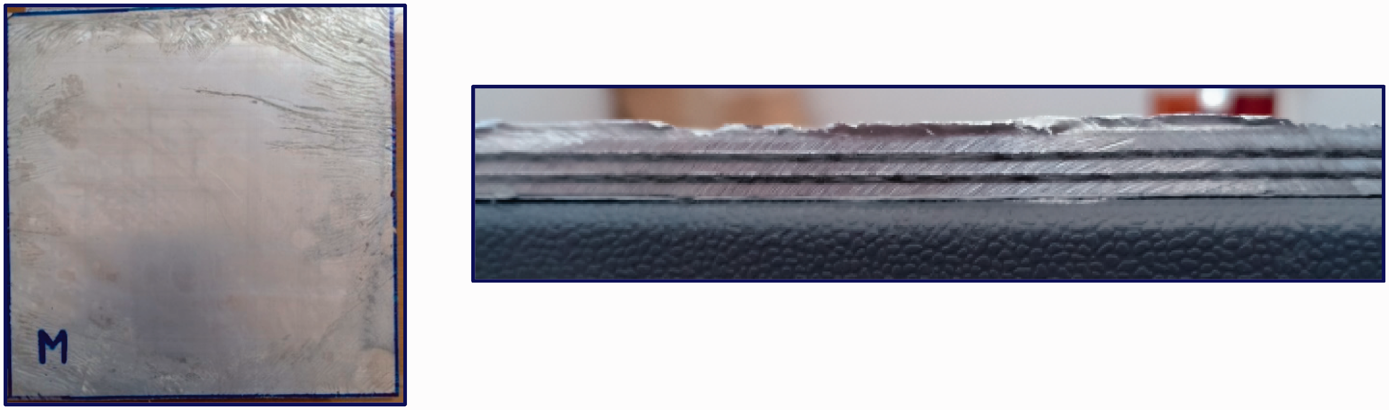
Mechanical and chemical treatments were conducted on Al-alloy sheets to ensure the proper adhesion among Al-sheets and polymer composites. The mechanical treatment was performed through rinsing Al-sheets with acetone and abrading them smoothly with # 400 grits sandpaper and then rinsing the sheets with tap water and finally drying them in an oven. The chemical treatment was performed on the mechanically treated sheets by hydrochloric acid (HCl) with 11% volumetric concentration to elevate Al-surface roughness. Acid etching was performed at ambient temperature for 30 min. Al-sheets were then rinsed with water and were dried out. Afterward, Al-sheets were immersed in 5 wt. % NaOH solvent at 70 °C temperature for 5 min. The oxidized Al-sheets were dried in an oven to stabilize the oxide layer and then were washed with tap water to remove the oxide residue [12,38]. Figure 1 shows the steps of mechanical and chemical surface treatments of Al-sheets. Figure 2 shows the difference between as received and treated Al-sheets.
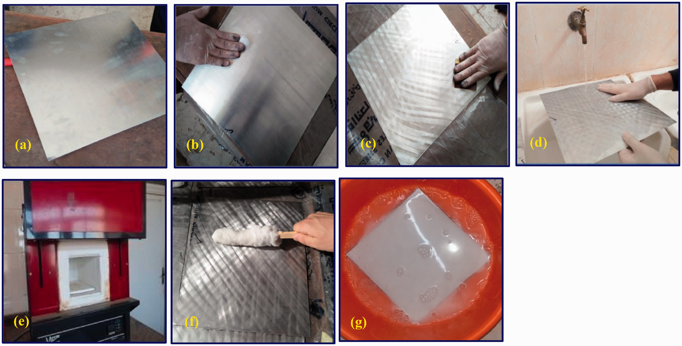
(a) As received Al-sheet, (b) rinsing Al-sheets with acetone, (c) abrading Al-sheets with sandpaper, (d) rinsing the sheets with tap water, (e) drying Al-sheets in an oven, (f) acid washing, and (g) immersing Al-sheets in 5 wt. % NaOH solvent.

(a) Al-sheet as received and (b) treated Al-sheet.
Distribution of HNTs into the epoxy resin
HNTs were added to acetone (10 wt. % of epoxy) and sonicated for 30 minutes. Epoxy was added to the mixture (acetone with HNTs) and the mixture was sonicated for 2 hours. Acetone was used as a diluent for araldite to reduce its viscosity leading to an adequate distribution of HNTs into the epoxy and break the clusters of HNTs into smaller ones [8,49]. The sonication process was carried out via high intensity ultrasonic processor (Hielscher UP200S) under power level of 200 watts in an impulse pattern of 0.5 s on/off cycle, frequency of 24 kHz and amplitude of 70%. Sonication is used to ensure the good dispersion of HNTs in the epoxy and break up the aggregations thus the compatibility of HNTs with epoxy resin can be enhanced [50]. As sonication occurs, the mixture was placed in an ice-water bath in order to reduce the emitted temperature [39]. To evaporate acetone, the mixture was heated in an oven to 80 °C for 2 hours. Then, the hardener was mixed with the epoxy filled with HNTs with a weight ratio of 2:1 as per the supplier recommendation. Then, it was manually stirred up for about ten minutes.
Fabrication of GLARE laminates filled with HNTs
GLARE (3/2) laminates with quasi-isotropic lay-up,
Hand lay-up followed by compression molding were used to fabricate GLARE laminates filled with different wt. % of HNTs (0, 0.25, 0.5, 1, 2 and 3 wt. %). The fabrication procedure is as follows: the mixture (epoxy + its hardener + HNTs) was uniformly spread upon the treated Al-sheets and woven E-glass fabric layers according to the required order. The constructed GLARE laminates were maintained at room temperature under pressure of 1.2 bars for 24 hours to be cured. To achieve the maximum strength and a full-cure treatment, the mechanical tests were performed after 21 days. As reported by [53], no residual stress is created in the fabricated GLARE laminates, since the cure cycle was at room temperature. The steps of the distribution of HNTs into the epoxy resin and the fabrication of GLARE laminates filled with HNTs are presented in Figure 3. The final product i.e. GLARE (3/2) is shown in Figure 4.

(a) Adding HNTs to acetone, (b) sonicating HNTs and acetone, (c) adding epoxy to acetone and HNTs, (d) sonicating the mixture, (e) heating the mixture, (f) mixing the hardener with epoxy and HNTs, (g) spreading the mixture on Al-sheet, (h) spreading the mixture on E-glass fabric, (i) Putting the upper Al-sheet, (j) primarily constructed GLARE, and (k) GLARE under pressure of 1.2 bars.
The final fabricated GLARE (3/2).
Mechanical characterization
The tensile, flexural, in-plane shear, interlaminar shear, and bearing tests were conducted on 100 kN universal testing machine (Type: Jinan WDW, China (Mainland)) shown in Figure 5 at a speed of 2 mm/min. Impact tests were conducted on Izod impact testing machine (Type: Avery Denison) at a velocity of 3.65 m/s. Five samples for each GLARE laminate type and for each test were tested and the average value was recorded.

(a) The tensile testing machine and (b) an enlargement view A.
Tensile test
Specimen's dimensions are 250 × 25 mm2 according to ASTM D3039 [54]. The average thickness of the specimens is 4.0±0.27 mm. From the experiment, the stress-strain curve for each specimen was recorded, and the ultimate tensile strength (
Flexural test
Flexural tests were performed according to JIS K7055 [55]. A three-point bending test jig was attached to the universal testing machine grips, Figure 6(a). The dimensions of the specimen are 170 × 15 mm2, Figure 6(b). The flexural strength (
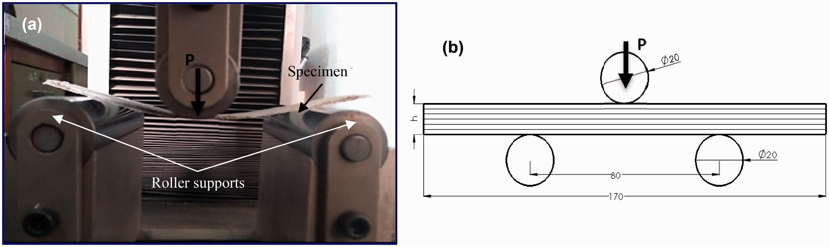
(a) Three-point bending test setup and (b) specimen’s dimensions are in mm.
In-plane shear test
In-plane shear tests were conducted using Modified Wyoming Iosipescu shear fixture shown in Figure 7(a) according to ASTM D 5379/D 5379 M [56]. Specimens were cut into strips with 76 × 19 mm2. A 90° double V-notches were machined at specimen mid-length through the specimen thickness for a depth of 3.8 mm and the notch root radius is 0.157 mm as shown in Figure 7(b). The specimen was inserted into the fixture with special attention to ensure that the specimen notches were aligned with the loading action line, Figure 7(a). The notches influence the shear strain along the loading direction, leading to a more uniform distribution of stresses than would be without the notches. By applying two force couples that generate two counter-acting moments, a pure and uniform shear stress state is generated at the section between the two notches. A compressive force was loaded normally to the specimen’s longitudinal axis.

(a) Modified Wyoming Iosipescu shear test fixture and (b) specimen’s dimensions are in mm.
In-plane shear strength (τxy) was calculated as:
As shown in Figure 7(a) for the modified Wyoming Iosipescu shear test fixture, the left half of the fixture is fixed rigidly to the base plate along with spacer block. There is a guide way on the spacer block of the left half to prevent the twisting of the movable (right) half. The entire front face of the specimen remains visible during testing and the progress of failure can be monitored visually. The principle of the test is to apply a set of prescribed displacements on the V-notch specimen, so that the central region of the sample is under a state of constant pure shear. These displacements are achieved through relative movement of the movable half with respect to the fixed half. Iosipescu test fixture is attached to the grips of the universal testing machine. A compressive load is applied on the movable half of the fixture.
Figure 8 illustrates the body, shear force, and bending moment diagrams of the Iosipescu shear test specimen. The main features of this test are that the force couples have produced a pure shear stress state at the specimen mid-length by applying two counteracting moments and also, a constant shear force state through the middle section of the test specimen can be achieved.

(a) Free body, (b) shear force and (c) bending moment diagrams of Iosipescu shear test.
Interlaminar shear test
Short beam shear (SBS) tests were carried out according to ASTM D2344 [57], which requires (span/thickness) ratio of 4.5 and (length/thickness) ratio of 6.0. The main advantage of SBS test is the simplicity and the ease of its conductance. Each specimen was placed on two roller supports that allow lateral motion. The compressive load was applied directly at the center of the specimen. The SBS specimen was loaded until failure occurs (longitudinal delamination between layers). Deflection was recorded as the measured vertical displacement at the loading nose. Details about the SBS test jig are illustrated in Figure 9. The interlaminar shear strength (ILSS) was determined as:
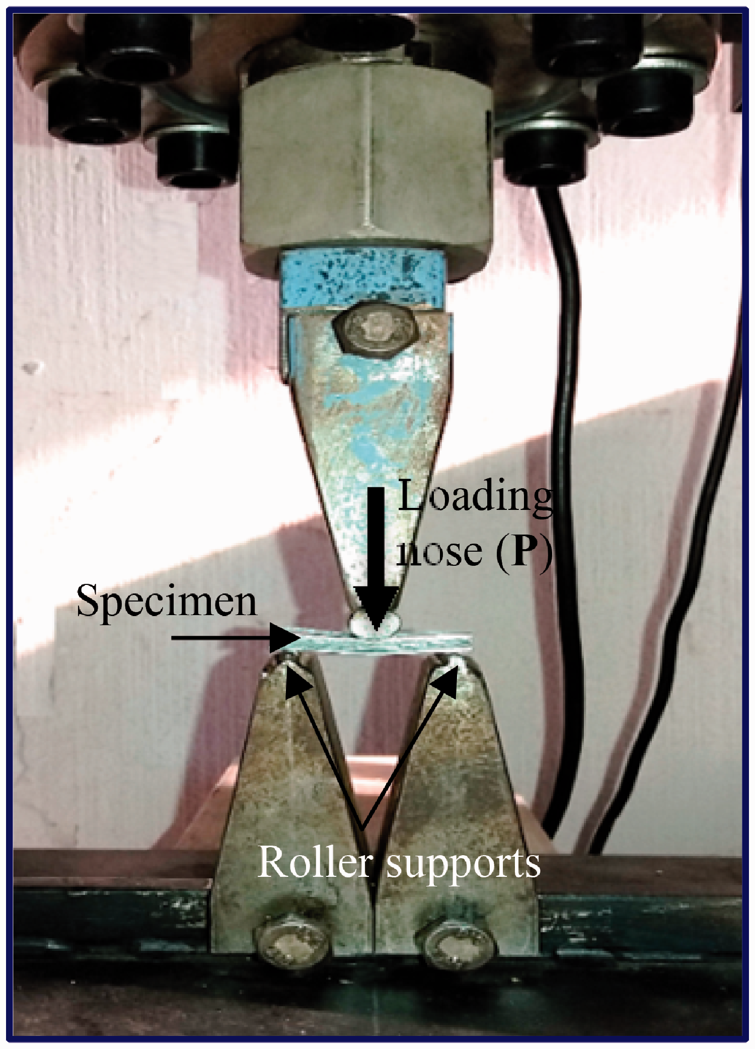
Short beam shear (SBS) test jig.
Bearing test
Bearing tests were conducted according to ASTM D5961/D5961M [58]. Figure 10 shows bearing test setup and the dimensions of pin loaded test specimen. Test specimens were cut into strips with 130 × 36 mm2. Edge distance (e)/hole diameter (d) and width (w)/hole diameter (d) ratios were selected to be 3 and 6, respectively. Bearing strength (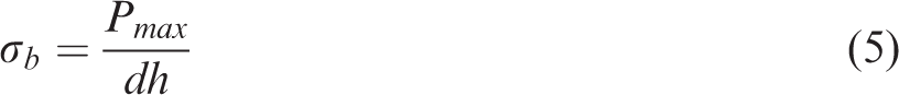

(a) Bearing test setup, (b) schematic diagram of test setup, and (c) specimen’s dimensions are in mm.
Impact test
Impact tests were conducted to investigate the energy absorbing capacity of the fabricated GLARE laminates using Izod impact testing machine shown in Figure 11(a). Specimens were cut into strips with 64 × 12.7 mm2as per ISO 180 [59], Figure 11(b). Izod impact test procedure can be summarized as follows: At first, the specimen was positioned in the vice with a centering device adapted as a vertical cantilever beam. Then, the hammer was set in the raised position. The pointer was set on upper limit of the scale as zero point. Finally, the hammer was released with a velocity of 3.65 m/s. The absorbed energy was recorded on the machine scale. The impact strength of un-notched flat-wise specimens (

(a) Izod impact testing machine and (b) specimen’s dimensions are in mm.
Microstructure examination
Damage mechanisms in GLARE laminates under different loading conditions can be classified as (1) the damage corresponding to the metallic layers i.e. the metal plastic deformation and rupture, (2) the damage relevant to the bonding between the metallic layers and polymer composite, and (3) the damage related to the composite laminate itself i.e. matrix cracking, fiber breakage, fiber pull-out, and delamination. To understand how HNTs impact the fracture behavior, the specimens were examined using scanning electron microscope (SEM) JSM 6100. Fractured surfaces were coated with gold and kept in an ionizer. Images were taken by subjecting the surfaces to a voltage of 20 kV.
Results and discussions
Morphological analysis
SEM of nanocomposite
Uniform dispersion of nanoparticles in polymer matrix is a key factor for fabricating high-performance polymer nanocomposites. The homogeneous dispersion of HNTs and the strong interfacial interactions between polymer matrix and HNTs can effectively improve the mechanical properties of the produced polymer nanocomposites [60]. SEM images of nanocomposites shown in Figure 12 display the dispersion of HNTs. It is demonstrated from Figure 12(a) and (b) that 0.25 and 1 wt. % of HNTs was uniformly dispersed into the epoxy and no critical aggregation of HNTs was recorded i.e. one can see individual particles. But for the higher concentration of HNTs i.e. 3 wt. %, aggregation of HNTs was detected i.e. HNTs were non-uniformly dispersed in the epoxy matrix, as illustrated in Figure 12(c). The morphological study of the composite part filled with 3 wt. % of HNTs revealed that HNTs were non-uniformly dispersed in the epoxy matrix, forming a unique microstructure with a large number of HNT-rich composite particles enveloped by a continuous epoxy-rich phase. Some HNTs were randomly dispersed in the matrix with large inter-tube distances, while others were dispersed in the epoxy with much shorter inter-tube distances, resulting in the formation of many HNT-rich regions. It is clear from Figure 12(a) and (b) that HNTs were efficiently dispersed in epoxy. That is due to sonication shown in Figure 3(d) which was used to ensure the good dispersion of HNTs in epoxy and break up the aggregation thus the compatibility of HNTs with epoxy resin can be enhanced [50]. The sonicator introduces high local shear stress and unties the aggregated HNTs entanglements. At high HNTs level (3 wt. %), the aggregation was formed. Aggregation associated with the high content of nanofillers is considered the main reason of mechanical properties degradation compared to the lower content. Aggregated nanofillers offer stress concentration and facilitate damage initiation and growth.

SEM of composite surface of GLARE laminates filled with HNTs (a) 0.25, (b) 1, and (c) 3 wt. %.
Field emission scanning electron microscope (FE-SEM)
FE-SEM is used to determine the chemical composition of the samples and the distribution of the elements. FE-SEM was performed on the surface of composite part of GLARE filled with 1 wt. % of HNTs. Figure 13 shows a homogeneous distribution of elements in the structure. This is due to sonication during the fabrication process. It can be seen that carbon, found in epoxy, covers almost the entire surface of the sample. Al, silicon, and oxygen, found in HNTs, are found less in the structure of the sample.
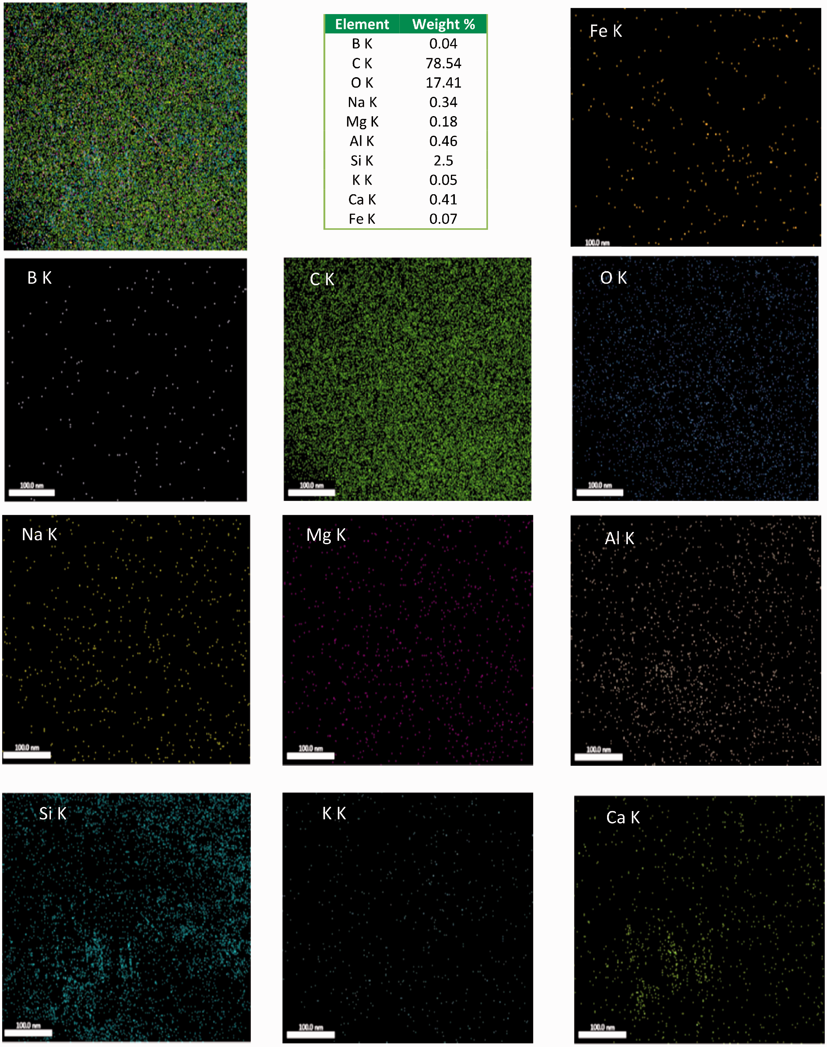
FE-SEM of GLARE filled with 1 wt. % HNTs.
Energy-dispersive X-ray spectroscopy (EDX)
Energy-dispersive X-ray spectroscopy (EDX) shown in Figure 14 is an analytical technique used for the elemental analysis or chemical characterization of a sample. GLARE filled with 1 wt. % of HNTs was illustrated by EDX, Figure 14. EDX profile was acquired on a single spot of the composite part.
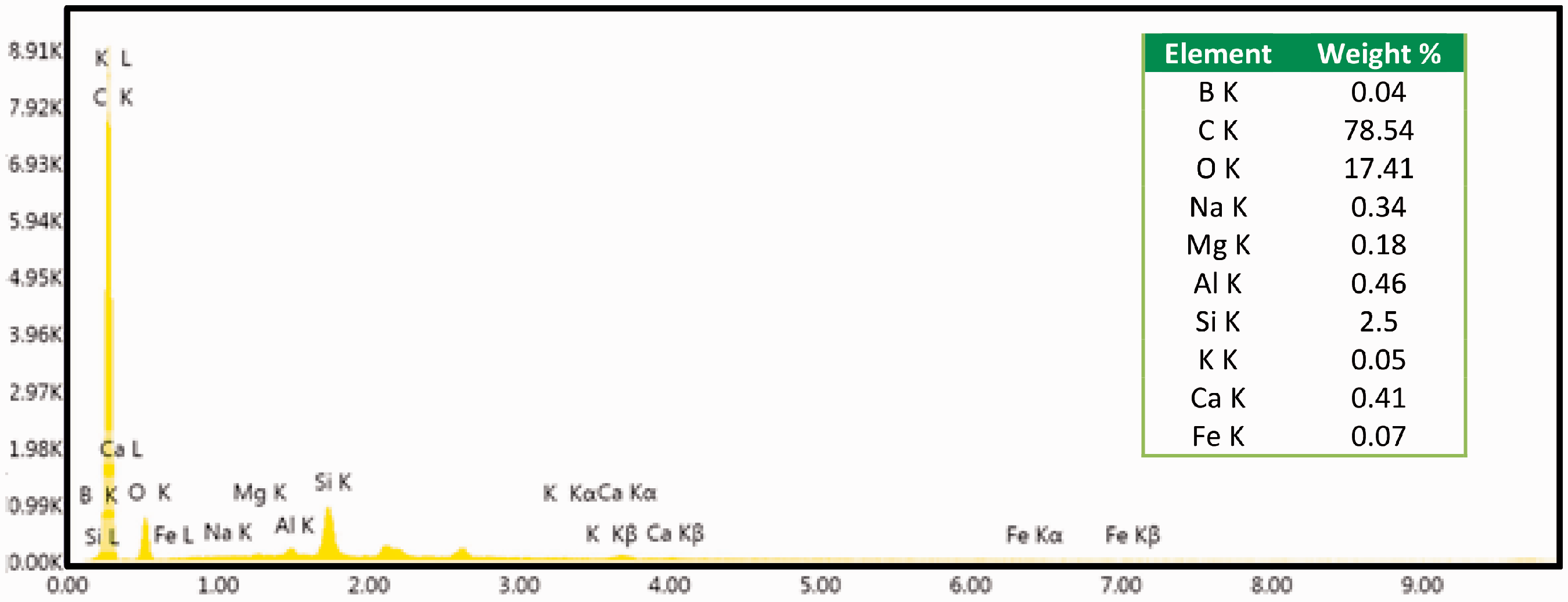
EDX spectrum of GLARE filled with 1 wt. % of HNTs.
Tensile test
Tensile properties
Tensile stress-strain curves for GLARE specimens filled with different wt. % of HNTs are shown in Figure 15 as obtained from the computer unit connected to the testing machine. The results presented in Figure 15 are for the most representative sample for each configuration. It is obvious that the specimens show different trends that resemble different failure mechanisms during deformation under tensile loading. All specimens except (GLARE filled with 3 wt. % of HNTs) behave almost linearly followed by sudden drop after peak stress is reached, leading to the catastrophic two-piece failure of the specimens. The specimen filled with 3 wt. % of HNTs has also a linear trend but it does not behave a catastrophic failure as it behaves a two-steps failure, i.e. primary and secondary failure modes.

Tensile stress-strain curves of the fabricated GLARE laminates filled with different wt. % of HNTs.
GLARE specimen filled with 3 wt. % of HNTs behaves linear up to the peak stress followed by a slight stress drops with a hesitation in the stress value till fracture occurs, i.e. progressive damage. The damage process starts with fiber fracture which yields a deviation from the initial proportional loading of tensile stress in the stress-strain curve. Further deformation causes sequential fiber breakage which is translated into small deviations of stress in the stress-strain curve followed by unstable delamination failures at the end of the test. The drop in the ultimate load is due to long delaminations between the fiber reinforced layers. After the initial failure, different damage modes, such as gradual fragmentations (multiple fractures) in glass fiber have occurred, resulting in the formation of a zigzag pattern in the stress-strain curve [61]. The specimen passes various stages before fracture. Ravichandran et al. [62] and Arumugam et al. [63] recorded the same phenomenon (zigzag pattern in the stress-strain curve after the peak stress) for CuO and chitosan nanofilled composites, respectively.
It is clear from Figure 15 that the highest peak and the highest slope were observed for GLARE filled with 1 wt. % of HNTs. On the contrary, the lowest peak and slope were noticed for pristine GLARE. The effect of the incorporation of 0.25, 0.5, 1, 2 and 3 wt. % of HNTs on the tensile properties of GLARE specimens was presented in Figures 16 to 19, for tensile strength, failure strain, Young's modulus, and modulus of toughness, respectively. Numerical values of the absolute tensile properties and their normalization with respect to those of the neat GLARE are recorded in Table 4, in addition to the standard deviation (SD). The recorded absolute values are the average of five tested samples and the normalized values are to emphasize the improvement.

Variation of the average ultimate tensile strength versus wt. % of HNTs.

Variation of the average failure strain versus wt. % of HNTs.
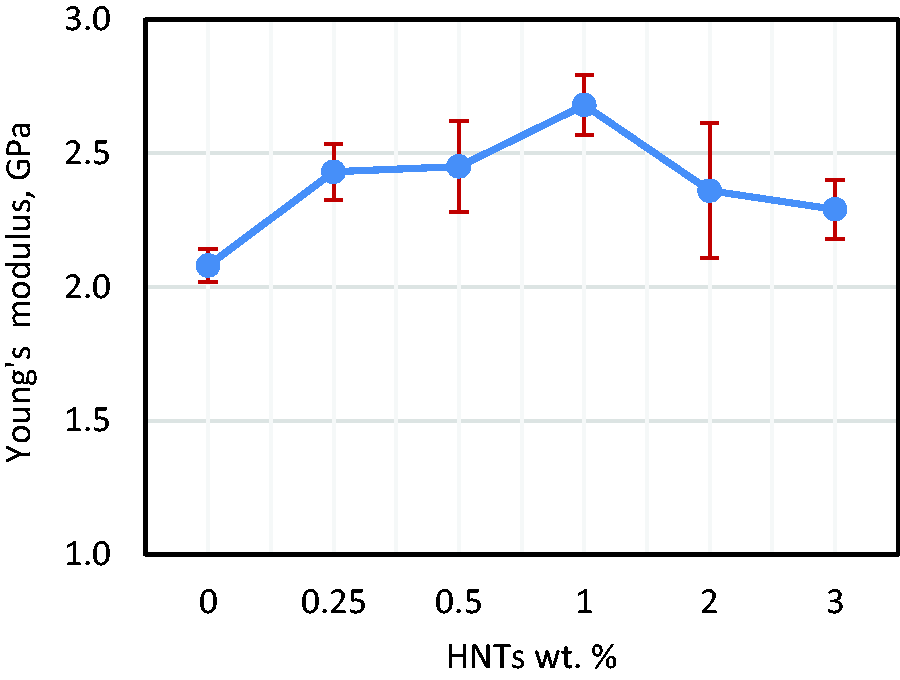
Variation of the average Young's modulus versus wt. % of HNTs.
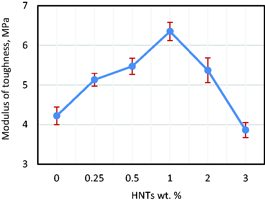
Variation of the average toughness modulus versus wt. % of HNTs.
Average absolute and normalized values of the tensile properties of GLARE laminates filled with HNTs.
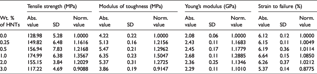
It is interesting to observe that GLARE filled with 1 wt. % of HNTs exhibits maximum improvements of 35.67, 8.50, 28.85, and 50.47% in the average tensile strength, failure strain, Young's modulus, and modulus of toughness, respectively. This is due to the better dispersion of HNTs in the epoxy matrix as shown in Figures 12 and 13, and the improved inter-tubular and interfacial interactions between HNTs and epoxy, which are beneficial for the improvement of strength and modulus. This finding is consistent with [44] for HNTs and polypropylene matrix.
The average tensile properties of GLARE laminates filled with 0.25, 0.5, and 2 wt. % of HNTs were higher compared with those of neat GLARE. An enhancement of 16.16, 0.49, 16.83, and 21.56% in the average tensile strength, failure strain, Young's modulus, and modulus of toughness was attained by the addition of 0.25 wt. % of HNTs to epoxy of GLARE. The addition of 0.5 wt. % of HNTs exhibits an enhancement of 21.68, 1.14, 17.79, and 29.62% in the average tensile strength, failure strain, Young's modulus, and modulus of toughness of GLARE, respectively.
The improvement in the failure strain suggested that HNTs could improve the energy absorption and deform together with the matrix without slippage. The addition of proper amount of HNTs increases Young's modulus, which is due to that the presence of micro/nanoparticles, with higher modulus than epoxy matrix, as reinforcements impart greater stiffness than the unmodified epoxy matrix [43,64,65]. Such behavior is generally in consistence with the well-known rule of mixture.
The enhancement in toughness can be attributed to the increased resistance to crack propagation via number of possible toughness mechanisms such as crack pinning, crack deflection, particle-debonding, plastic void growth, plastic deformation, and particle-pullout [65]. Crack deflection is usually recognized as an effective toughening mechanism for nanoparticles with high aspect ratios. In the vicinity of individual HNTs or bundled HNTs, crack deflection introduces sliding or tearing loading, thus increasing the energy consumed for crack propagation. After crack initiation, the bridged nanotubes at the crack front could be completely pulled out or fractured, depending on the interfacial adhesion between the nanotubes and epoxy matrix [47,66]. HNTs could resist crack propagation through characteristic crack tip bifurcation which often leads to increased toughness [67]. The nanotubes debonding, fracture, void growth around nanotubes, and crack deflection, and crack pinning, all could contribute to the toughening effect of HNTs. Almost all those energy absorbing processes for toughening can be found.
A reduced improvement was noticed for GLARE filled with 2 wt. % of HNTs exhibiting an improvement of 20.29, 2.29, 13.46, and 27.25% for, respectively, the average tensile strength, failure strain, Young's modulus, and modulus of toughness over pristine GLARE. This is because the low concentration of HNTs, i.e. 0.25 and 0.5%, shows a better dispersion of HNTs in the resin as shown in Figure 12 and the reasonable wettability of glass fiber and Al-sheets with the nano-modified resin than the high concentration, i.e. 2 wt. % or more. These results agree well with those reported by [32].
A decrease in the tensile properties was observed when HNTs loading was 3 wt. %. A reduction of 9.12, 12.25, and 8.53 for, respectively, tensile strength, failure strain, and toughness modulus over pristine was noticed. On the contrary, an improvement of 10.1% was recorded for Young's modulus. The incorporation of more and more nanofillers results in very high attractive forces between the particles, inducing a strong tendency to aggregate [68,69] as shown in Figure 12. These aggregations have a higher surface area, which helps in the formation of enclosed air bubbles from the atmosphere. Hence, this reduces the mechanical properties of polymeric nanocomposites [70]. The aggregations cause defects in nanocomposite laminates and act as stress concentrations that generate cracks and cause early failure; hence a reduction in the mechanical properties was attained [71].
The improvement in the mechanical properties of GLARE laminates filled with HNTs happened due to the rich interfacial interactions between HNTs/epoxy matrix and excellent HNTs dispersion with low agglomeration (up to 2 wt. % of HNTs). This observation is consistent with [72]. The reduction in the mechanical properties at higher loading (i.e. 3 wt. % HNTs) may be attributed to the weak matrix-fiber interfacial interactions, few air voids, and aggregates of HNTs, Figure 12. Such aggregates acting as weak points and failure initiation sites. Similar observations have been reported by [73], for HNTs filled epoxy nanocomposites.
Failure mechanism
Severe delamination between Al-sheets and polymer composites, Al-sheet and fiber breakage can be noticed for GLARE filled with 0 and 3 wt. % of HNTs under tensile loading, Figure 20(a) and (c). Delamination is attributed to the weak interfacial bond between glass fiber reinforced composites/Al-sheets. Slight separation between Al-sheets and polymer composites can be noticed for GLARE filled with 1 wt. % of HNTs accompanied with fiber and Al-sheets breakage, Figure 20(b). SEM images of fracture surfaces of composite laminates of GLARE show poor adhesion between fiber/matrix, matrix dislocation, fiber breakage and fiber pull-out for pristine GLARE and GLARE filled with 3 wt. % of HNTs, Figure 21(a) and (c). On the contrary, a perfect bond between glass fiber/matrix was noticed for GLARE filled with 1 wt. % of HNTs, Figure 21(b).
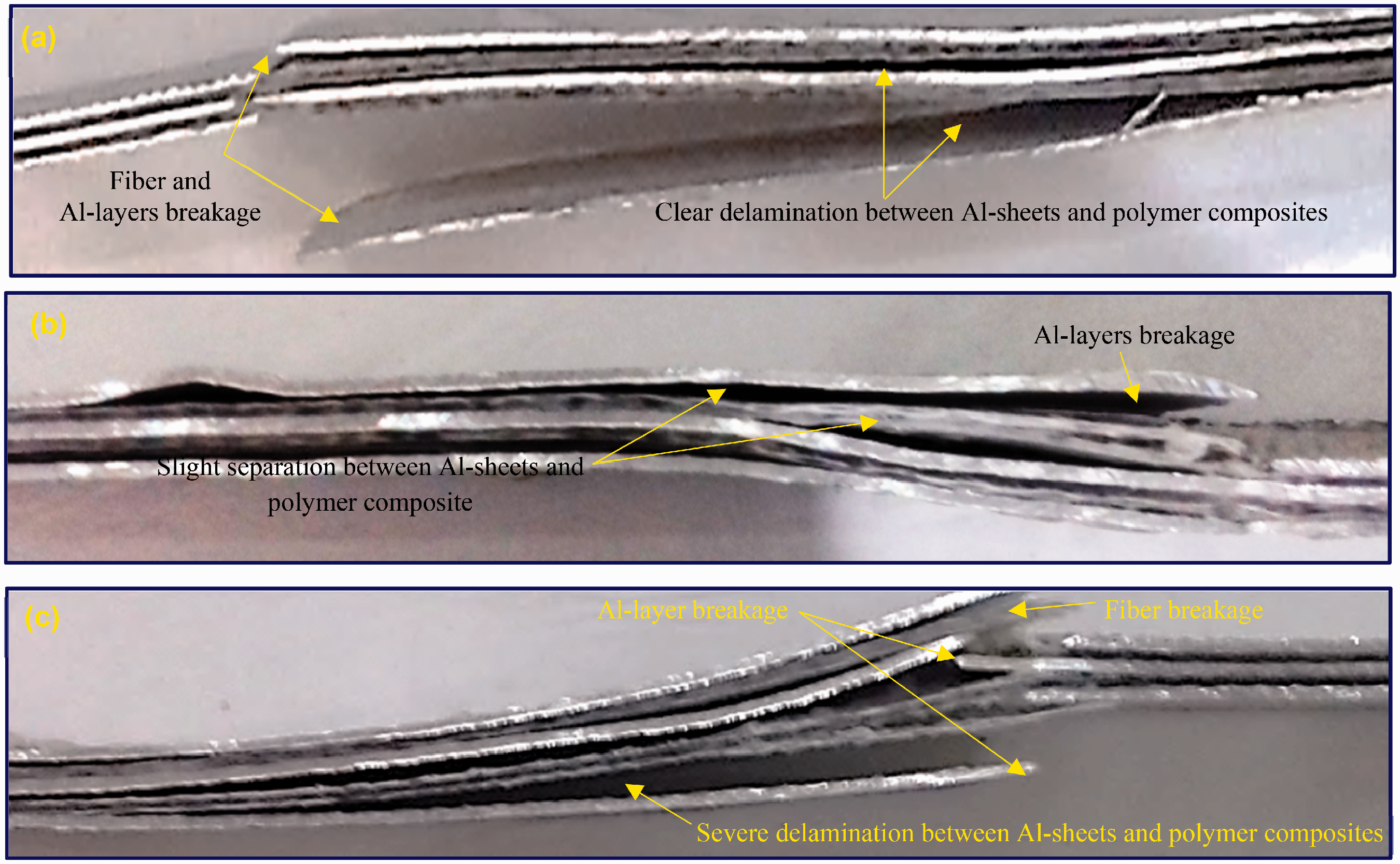
Damage due to tensile loads: GLARE samples filled with (a) 0, (b) 1, and (c) 3 wt. % HNTs.

SEM of damaged tensile GLARE samples with (a) 0, (b) 1, and (c) 3 wt. % HNTs.
Three point bending test
Flexural properties
A comparative plot of flexural stress-flexural strain curves for the fabricated GLARE laminates filled with different wt. % of HNTs is presented in Figure 22. The results presented in Figure 22 are for the most representative sample for each configuration. Flexural stress-flexural strain curves exhibit an essentially linear elastic behavior with rapid and steep load rise up to a certain point after which a nonlinear behavior with a very slow load rise was attained. After the peak point, the load decreases. The load drop is associated with the delamination and the failure of matrix and fiber. The highest peak was noticed for GLARE filled with 1 wt. % of HNTs. On the contrary, the lowest peak was recorded for GLARE filled with 3 wt. % of HNTs.
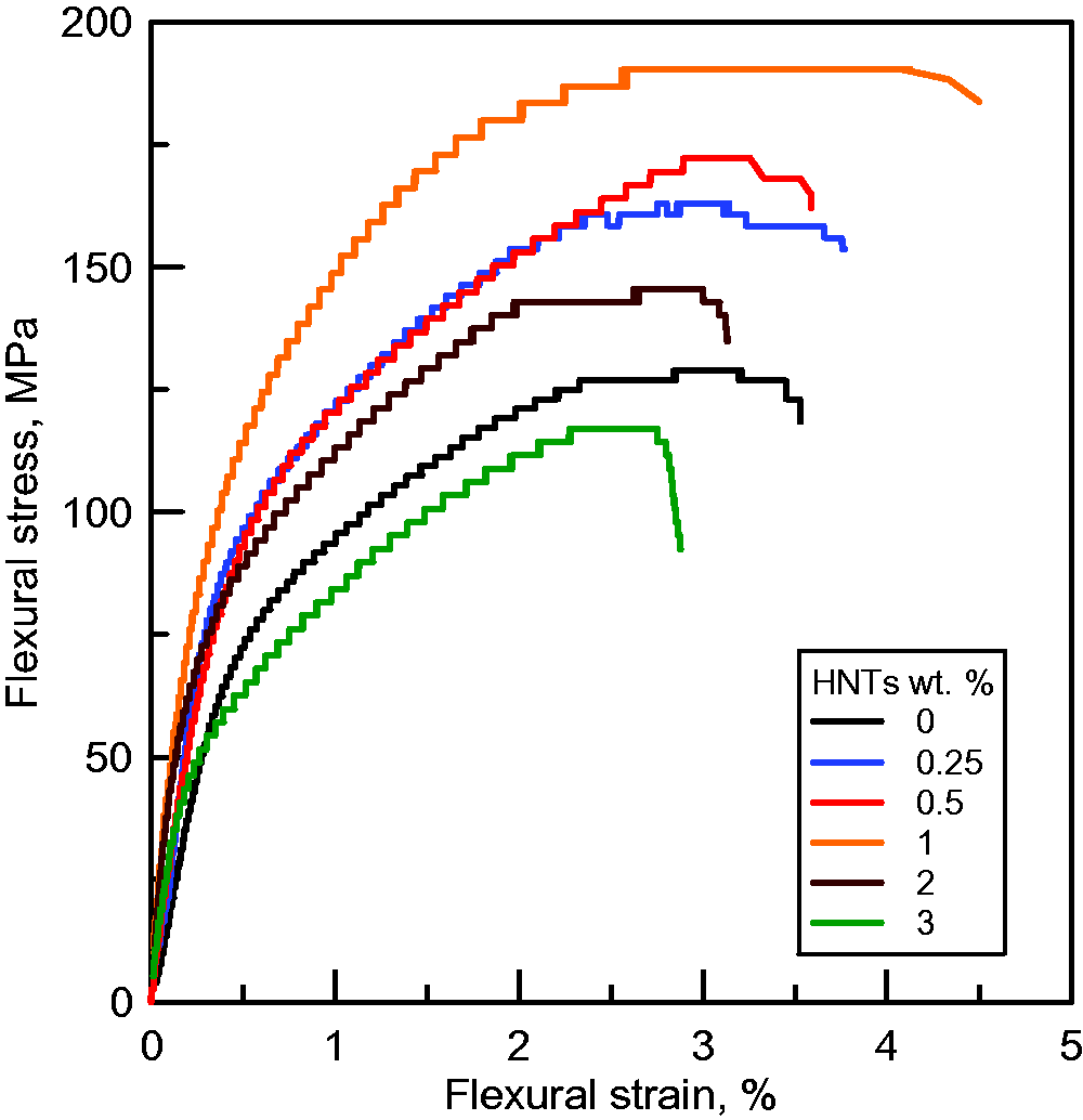
Flexural stress-flexural strain curves for GLARE laminates filled with different wt. % of HNTs.
A maximum enhancement of 50.27 and 30.43% in the average flexural strength and flexural strain was recorded for GLARE filled with 1 wt. % of HNTs, as shown in Figures 23 and 24. This improvement could be directly related to the matrix properties influenced by the dispersion of HNTs, Figure 12(b). An enhancement of 40.3% was obtained by [32] using 0.5 wt. % of MWCNTs, which are much more expensive than HNTs. It is obvious from Figure 23 that adding HNTs up to 2 wt. % improves the average flexural strength. An enhancement of 26.45, 33.59, and 12.88% in the average flexural strength was obtained for GLARE filled with 0.25, 0.5, and 2 wt. % of HNTs. By the addition of 3 wt. % of HNTs, a reduction of 9.23% in the average flexural strength was attained. The increase in the average flexural strength of GLARE laminates filled with HNTs up to 2 wt. % can be attributed to the enhancement in the interfacial bonding between the filler and the matrix, thus increasing the surface area of matrix/filler interaction. As a result, this leads to good stress transfer from the matrix to the nano-fillers, thus resulting in improved flexural strength [65].
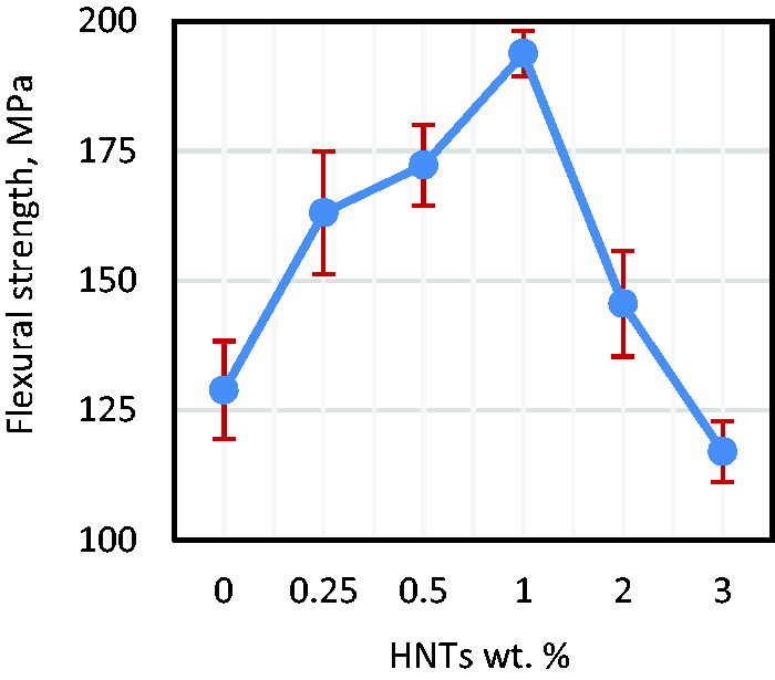
Variation of the average flexural strength versus wt. % of HNTs.

Variation of the average flexural strain versus wt. % of HNTs.
Figure 24 shows that the average flexural strain increases with the addition of HNTs up to 1 wt. %. An improvement of 9.28 and 15.36% in flexural strain was attained by the integration of 0.25 and 0.5 wt. % of HNTs, respectively, as compared to neat GLARE. On the contrary, a reduction of 7.83 and 16.52% in flexural strain was noticed for 2 and 3 wt. % of HNTs. It was noticed from Figure 25 that 0.5 wt. % of HNTs gives the highest flexural modulus. An enhancement of 24.30 and 38.89% in flexural modulus was achieved by the incorporation of 0.25 and 0.5% of HNTs, respectively, as compared to neat GLARE. The enhancement in the specimen flexural modulus can be due to the presence of rigid fillers that have higher modulus than epoxy matrix [65]. On the contrary, a reduction of 11.70, 15.16 and 28.57% in flexural modulus was obtained with the inclusion of 1, 2 and 3% of HNTs. These observations are consistent with that was obtained by [74], who recorded an improvement up to 20, and 72.8% in the flexural strength and modulus with the addition of 1 wt. % HNTs to epoxy resin compared with pure epoxy.
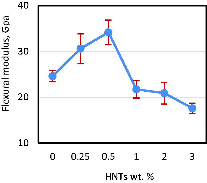
Variation of the average flexural modulus versus wt. % of HNTs.
The increasing trend of flexural strength could be explained by the two opposite effects resulting from the incorporation and good dispersion of HNTs shown in Figure 12(a) and (b) and the strengthening effect of the matrix and interface. The deterioration effect is resulted from the agglomerations of HNTs presented in Figure 12(c) and poor wetting behavior due to the high viscosity of epoxy [75]. Strong attractive fiber Vander Waals forces cause HNTs to agglomerate. These agglomerations create stress concentration zones which might act as crack initiators which reduce the strength of the nanocomposite by stress concentration effect. Table 5 shows the improvement in the flexural properties of GLARE laminates filled with different wt. % of HNTs with respect neat GLARE.
Average absolute and normalized values of the flexural properties of GLARE laminates filled with HNTs.

According to [76], adding more HNTs decreases the flexural properties. This can be due to the presence of filler agglomerations and micro-voids at higher HNTs contents. At high concentration of HNTs, they are poorly dispersed within the matrix-forming agglomerations that act as stress concentrators, which in turn cause reduction in flexural strength. Additionally, it was observed an increase in matrix viscosity due to the increase in HNTs content, which in turn allowed small air-bubbles to be trapped in the resin during the mixing process forming tiny voids in the sample. This in turn resulted in sample failure at relatively low stress. In contrast, with a lower loading of HNTs, the potential of micro void formation is less, and the dispersion is more uniform that both lead to strength improvement [77]. This observation is consistent with that reported by [44] in their study of HNTs-filled polypropylene nanocomposites. It was found that the addition of HNTs resulted in a slight improvement in flexural strength of neat polymer. However, at higher HNTs loading (8 wt. %), flexural strength decreased due the tendency of HNTs to agglomerate.
Failure mechanism
Figure 26 shows the damage in GLARE samples filled with 0, 1, and 3 wt. % of HNTs subjected to flexural loads. In pristine GLARE, obvious detachment between the polymer composite and Al-sheet at the compressive side and slight delamination at the tensile side were observed indicating weak interfacial adhesion. For GLARE filled with 1 wt. % of HNTs, nanocomposite laminates are perfectly bonded to Al-layers. Slight delamination between the Al-layer and the polymer composite was noticed in the tensile side. For GLARE filled with 3 wt. % of HNTs, clear delamination was observed between Al-layers and composite laminates. The difference between the damage in pristine GLARE nad GLARE filled with 3 wt. % of HNTs are as follows:
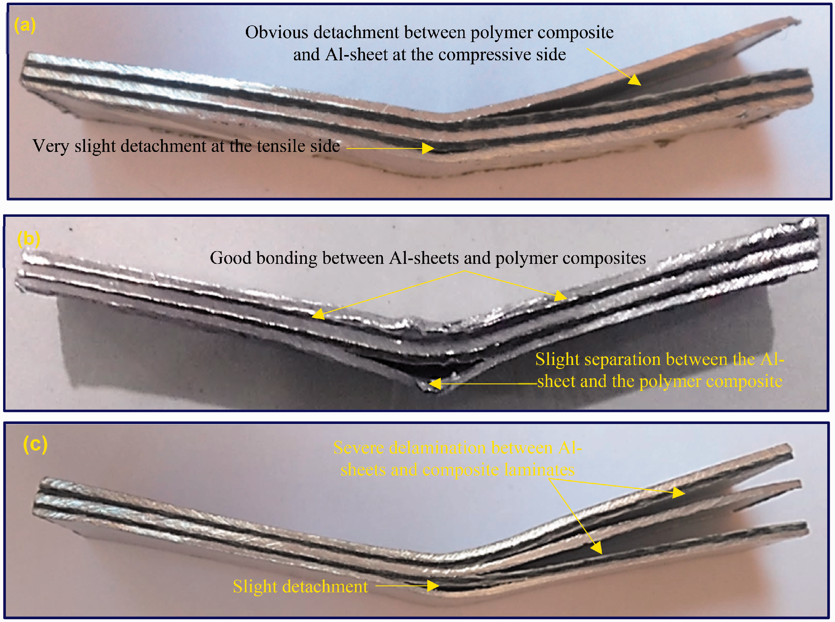
Damage due to flexural loads: GLARE samples filled with (a) 0, (b) 1, and (c) 3 wt. % HNTs.
In pristine GLARE, separation between the external Al-sheet and polymer composite at the compression side was noticed. In addition, very slight detachment between the external Al-layer and polymer composite at the tensile side was noticed, Figure 26(a).
In GLARE filled with 3 wt. % of HNTs, obvious delamination between the central Al-sheet and the two polymer composites at both sides (tension and compression) was noticed. Also, slight detachment between the external Al-layer and composite at the tensile side was attained, Figure 26(c).
SEM images show fiber breakage, delamination and debonding in pristine GLARE and GLARE filled with 3 wt. % of HNTs. Theses delamination and debonding show the weak adhesion between fiber/matrix, Figure 27(a) and (c). On the contrary, good adhesion between fiber/matrix was observed for GLARE filled with 1 wt. % of HNTs, Figure 27(b).
SEM of damaged bending GLARE samples with(a) 0, (b) 1, and (c) 3 wt. % HNTs.
In-plane shear test
In-plane shear strength
The effect of wt. % of HNTs on the in-plane shear stress-displacement curves of GLARE is displayed in Figure 28. The results presented in Figure 28 are for the most representative sample for each GLARE. The curves are almost linear in the initial portion. After a certain point, the curves become nonlinear due to the crack developing near the V-notches. With increasing the applied stress, the deviation from the linearity increases due to the accumulation of matrix cracks. After the peak point, the stress gradually decreases. The obvious differences between the elastic stages of different curves shown in Figure 28 are the slope of the curves, which gives an indication of shear modulus. It is clear that GLARE filled with 1 wt. % of HNTs has the highest slope indicating the highest shear modulus. Further increase in the amount of HNTs up to 2 wt. % reduces the trend but the slope is still higher compared with pristine GLARE. A reduction in the curve slope was noticed for GLARE filled with 3 wt. % of HNTs compared with the neat GLARE.

In-plane shear stress-displacement curves of GLARE laminates filled with different wt. % of HNTs.
Figure 29 shows the average in-plane shear strength of GLARE laminates filled with different wt. % of HNTs. It is clear that the inclusion of HNTs improves the in-plane shear strength up to 1 wt. %. Further increase in the amount of HNTs (i.e. 2 and 3 wt. %) reduces the trend. The performance is still higher for GLARE filled with 2 wt. % of HNTs compared with pristine GLARE. That is due to the heterogeneity in HNTs dispersion and the aggregation at high concentration levels as shown in Figure 12(c). However, the optimal enhancement in the in-plane shear strength was reported for GLARE filled with 1 wt. % of HNTs.

Variation of the average in-plane shear strength versus wt. % of HNTs.
As shown in Figure 29, the inclusion of HNTs with 0.25, 0.5, 1, and 2 wt. % shows an enhancement in the in-plane shear strength by 12.59, 18.65, 23.73, and 13.79%, respectively. The inclusion of 3 wt. % of HNTs reduces the in-plane shear strength of GLARE by 15.28%. With further increase in the concentration of nanoparticles, the agglomerations of nanoparticles can form a network through the whole polymer matrix and occlude the liquid polymer in their interparticle voids, thereby affecting the rheology of the composite underfill and giving a significant rise to the viscosity [78]. This in turn resulted in poor wettability of fiber and metal and poor adhesion is obtained. Table 6 shows the improvement in the in-plane shear, interlaminar shear, bearing and impact properties of GLARE laminates filled with different wt. % of HNTs with respect neat GLARE.
Average absolute and normalized values of the shear, bearing and impact properties of GLARE laminates filled with HNTs.

Failure mechanism
The damage in pristine GLARE and GLARE filled with 1 and 3 wt. % of HNTs subjected to in-plane shear loads is shown in Figure 30. Clear delamination between the composite laminates/Al-layers indicating poor interfacial adhesion and material crushing at the V-notches can be noticed in pristine GLARE and GLARE filled with 3 wt. % of HNTs. In GLARE filled with 1 wt. % of HNTs, good bonding between the layers can be noticed which in turn increases the in-plane shear resistance as compared with pristine GLARE and GLARE filled with 3 wt. % of HNTs. Also, slight delamination and minor material crushing was observed. As reported by [79], polymer matrices filled with nanoparticles offer more efficient stress transfer, which reduces the local stress concentration around the fiber/matrix interlayer and improves the interfacial adhesion and mechanical performance of composite laminates.

Damage due to in-plane shear loads: (a) pristine GLARE, (b) GLARE filled with 1 wt. % of HNTs, and (c) GLARE filled with 3 wt. % of HNTs.
Interlaminar shear test
Interlaminar shear strength
Interlaminar shear stress-displacement curves for most representative GLARE samples filled with HNTs are presented in Figure 31. It is obvious that the inclusion of HNTs has a significant effect on the interlaminar shear strength (ILSS) and displacement of GLARE (3/2). The response of all GLARE laminates is linear during the early stage of loading followed by a deviation from the linearity. This continues until a peak point is reached. After this peak point, the stress decreases accompanied with an audible sound. GLARE filled with 1 wt. % of HNTs possess the highest peak amongst the studied GLARE laminates. The lowest peak was associated with GLARE filled with 3 wt. % of HNTs. It is clear that both the in-plane shear and interlamiar shear strengths have the same trend.

Interlaminar shear stress-displacement curves of GLARE laminates filled with different wt. % of HNTs.
The average interlaminar shear strength (ILSS) of GLARE with different amounts of HNTs is illustrated in Figure 32. It is obvious that the improvement in ILSS reaches its maximum value of 72.08% with the addition of 1 wt. % of HNTs. Compared with unfilled GLARE; the addition of 0.25, 0.5, and 2 wt. % of HNTs gives an improvement of 35.78, 47.29, and 40.66% in ILSS. This is due to the strong physical bonding leading to decrease in the interatomic spaces enhancing the force of separation, this enhancement further leads to subsequent increase in inter-laminar shear strength due to higher magnitude of forces required to break the bond between HNT filler and the epoxy matrix [62]. Hussain et al. [80] proposed that the addition of nano-sized fillers to an epoxy matrix causes higher thermal residual stresses on the surface of the fibers, which increases the fiber–matrix interfacial bonding, leading to the improved ILSS. The addition of 3 wt. % of HNTs gives a reduction of 9.08 in ILSS of GLARE due to the aggregations as presented in Figure 12(c).

Variation of the average interlaminar shear strength versus wt. % of HNTs.
Failure mechanism
To investigate the reinforcing effects of HNTs on the ILSS of GLARE, the damaged areas of the composite samples after carrying out SBS tests were investigated and are shown in Figure 33. It is clear from Figure 33 that under the interlaminar shear loading, severe delamination propagating through Al-sheets/polymer composite interface was observed. This failure takes place due to shear forces between the layers indicating the relatively weak bond at the interface as shown in neat GLARE and GLARE with 3 wt. % of HNTs. However, the inclusion of 1 wt. % HNTs in the epoxy matrix was found to enhance the ILSS of GLARE by improving the interfacial bond.

Damage due to interlaminar shear loads: (a) pristine GLARE, (b) GLARE filled with 1 wt. % of HNTs, and (c) GLARE filled with 3 wt. % of HNTs.
SEM images in Figure 34(a) and (c) show fiber pull-out, fiber breakage, delamination and matrix cracking were recorded for GLARE filled with 0 and 3 wt. % of HNTs. Fiber breakage, fiber pull-out and slight delamination was recorded for GLARE filled with 1 wt. % of HNTs, Figure 34(b).

Typical failure modes in damaged GLARE samples filled with (a) 0, (b) 1, and (c) 3 wt. % HNTs under interlaminar shear loading.
Bearing test
Bearing strength
Figure 35 shows the bearing stress-displacement curves of the most representative pin-loaded GLARE samples with different wt. % of HNTs. The curves have linear trends up to a certain point at which the deviation from linearity was recorded. The nonlinearity is due to the progressive fiber debonding and delamination between fiber/matrix interfaces owing to the bearing loads. Progressive loading leads to ‘brooming’ failure at the edge of the hole at which the first-peak on the stress-displacement curve was noticed. The stress subsequently increases in a nonlinear mode accompanied with several peaks up to the ultimate bearing strength. Then the stress gradually decreases. The highest and lowest peaks were noticed, respectively, for GLARE filled with 1 wt. % of HNTs and original GLARE.

Bearing stress-displacement curves of pin-loaded GLARE specimens filled with different wt. % of HNTs.
It is clear from Figure 36 that the inclusion of HNTs enhances the average bearing strength of GLARE for the studied wt. % of HNTs. The average bearing strengths of GLARE laminates filled with 0.25 and 0.5 wt. % of HNTs are, respectively, increased by 20.71 and 22.40% compared with the unfilled GLARE specimens. A maximum improvement of 30.74% in the average bearing strength was recorded for GLARE filled with 1 wt. %. Transfer of stress from the epoxy matrix to the reinforcement is main responsible factor to improve the mechanical properties of nano-modified composites. In this, effective stress transfer depends on the interfacial interaction of the polymer matrix with nanofillers and on the nanofillers dispersion in the polymer matrix. It is a well-established fact that the slippage at the filler-polymer interface reduces the stress transfer efficiency due to large strain. Slippage at polymer/reinforcement interface is reduced due to the HNTs and this might be an acceptable reason for the improvement of mechanical properties of developed materials [81].
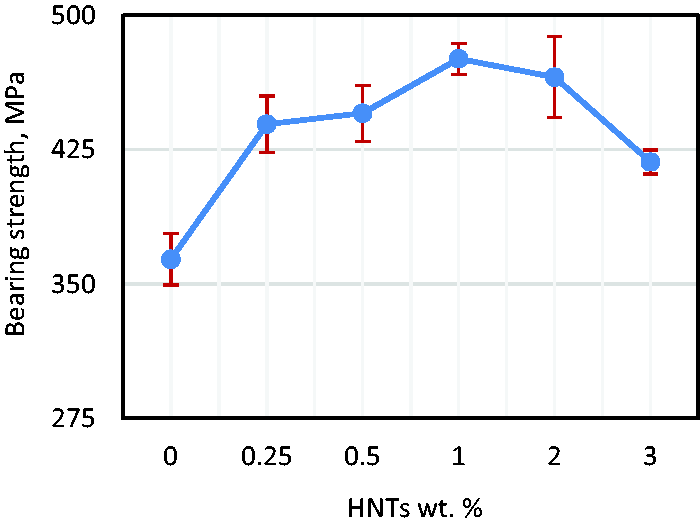
Variation of the average bearing strength versus wt. % of HNTs.
As shown in Figure 36, after 1 wt. % of HNTs the trend is reversed but still higher than neat GLARE. Improvements of 27.93 and 14.91% were recorded for GLARE filled with 2 and 3 wt. % of HNTs, respectively. The average bearing strength of GLARE filled with 3 wt. % of HNTs is higher than neat GLARE. This is unlike to tensile, flexural, in-plane shear, and interlaminar shear strengths. This may be due to the void formation in neat GLARE bearing samples. As a result, these voids raise the stress in the composite structure and behave like a crack. Hence, the voids decrease the strength under the load conditions. Bearing strength was also affected by the drilled holes for the bolt joints in the specimens as the drilled holes lead to stress concentrations as air gaps and nanoparticle agglomeration. Because the hole has the smallest cross section in the specimen, the damage occurs in these most vulnerable areas. These mentioned air gaps may occur near the hole, even on the surface of the hole and therefore, the area around the hole of the specimen would be weakened and more susceptible to damage under loading [82].
Failure mechanism
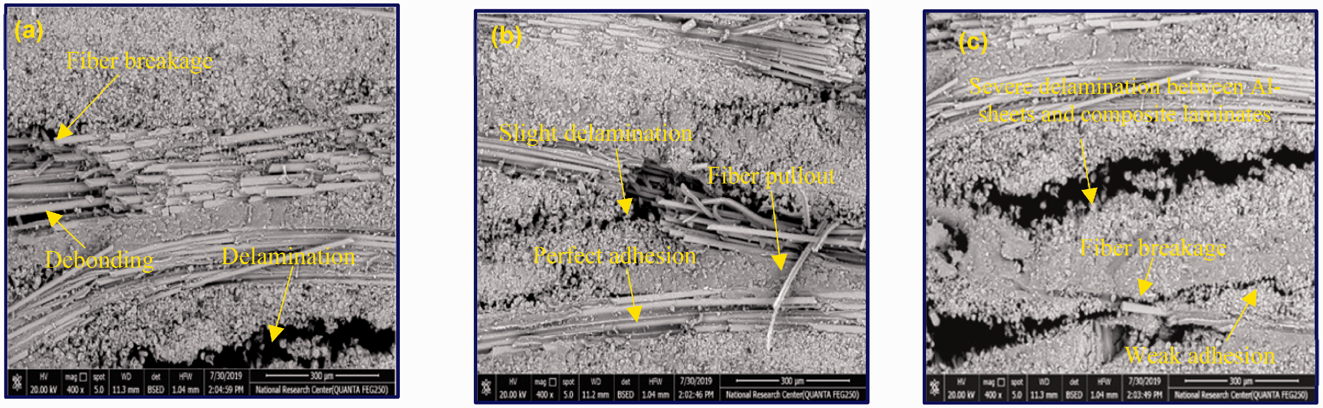
The damage in pristine GLARE and GLARE filled with HNTs subjected to tension bearing test is shown in Figure 37. It was noticed that for neat GLARE and GLARE filled with 3 wt. % of HNTs, severe detachment between Al-layers and composite laminates was attained around the hole. Clear cracks initiated from the hole and propagated to the specimen side edges leading to breakage in Al-sheets and fiber. By the inclusion of 1 wt. % of HNTs, nanocomposite laminates were perfectly bonded to Al-layers around the hole causing improved bearing strength as compared with pristine GLARE. Slight delamination between nanocomposites/Al-sheets was observed for GLARE filled with 1 wt. % of HNTs. Wrinkling in the outer Al-sheets causing delamination was noticed in all tested GLARE laminates. SEM images of failed specimens are shown in Figure 38. Weak adhesion between fiber/matrix for neat GLARE and GLARE filled with 3 wt. % of HNTs are shown in Figure 38(a) and (c). On the contrary, excellent adhesion was noticed for GLARE filled with 1 wt. % of HNTs, Figure 38(b). Surface cracks and fiber breakage were noticed for all specimens, Figure 38(d).

Damage due to tensile bearing loads: GLARE samples filled with (a) 0, (b) 1, and (c) 3 wt. % HNTs.

Typical failure modes in damaged bearing GLARE samples filled with (a) 0, (b) 1, and (c) 3 wt. % HNTs, and (d) surface view.
Impact test
Flat-wise impact strength
The impact strength of GLARE reached its maximum value with the addition of 1 wt. % of HNTs as shown in Figure 39. A maximum improvement of 51.52% in impact strength was recorded for GLARE filled with 1 wt. % of HNTs. At 1 wt. % of HNTs, HNTs may act as crack stoppers and increase the ability of the material to absorb energy by forming tortuous pathways for crack propagation which resulting in an increase in the impact strength. The impact strength of GLARE laminates filled with 0.25, 0.5, 2 and 3 wt. % of HNTs is higher than that of pristine GLARE. An increase of 35.99, 47.27, 27.84, and 20.03% in impact strength was noticed by the addition of 0.25, 0.5, 2 and 3 wt. % of HNTs to GLARE. A synergistic effect between HNTs and glass fibers has been observed. The amazing improvement in the mechanical properties of GLARE filled with HNTs is attributed to the large surface area to volume ratio of HNTs which creates an extreme interfacial area surrounding the HNTs and enhances the interfacial bonding between fiber and nanofilled epoxy. The improvement in the impact strength can be explained by two factors. On the one hand, the increased strength and toughness of the epoxy matrix caused by the addition of HNTs can be regarded as the most important reason. On the other hand, a strengthened interface between the glass fibers, Al-sheets and the modified matrix can be seen as another possible mechanism. Also, when the microcracks due to the impact loads were met with HNTs, they might be stabilized by crack bridging of HNTs. This result is consistent with that obtained by [83] who achieved 25% enhancement in Izod impact strength with the addition of 2 wt. % of HNTs to carbon/epoxy composite. As reported by [83], the improvement in Izod impact strength is owing to the toughening mechanisms brought by HNTs during the matrix cracking process, including microcracking, nanotubes pull-out, bridging and breaking.

Variation of average Izod impact strength versus wt. % of HNTs.
The enhancement in the impact strength might be attributed to the formation of strong and tough materials in the presence of HNTs, thus, it could be said that this increase in impact strength may be due to the intrinsic toughening property of HNTs. A better interfacial interaction may also impart an improvement on impact strength with high absorption energy during deformation. Good dispersion and proper distribution of nanotubes in the polymer matrix may also offer high impact energy for developed composites [43]. The large aspect ratio of HNTs may generate complex matrix-interaction during HNTs bridging, breaking and pull out that might promote plastic deformation of the matrix [73].
Failure mechanism
Figure 40 shows the damage in GLARE laminates filled with different wt. % of HNTs subjected to impact loading. For original GLARE and GLARE filled with 3 wt. % HNTs, severe delamination between Al-sheets/composite laminates can be observed. This reveals weak interfacial adhesion between Al-sheets and composite laminates as subjected to impact loading. On the other hand, a good interfacial adhesion between Al-sheets and nanocomposite laminates was attained for GLARE filled with 1 wt. % of HNTs. Slight detachment at the back face between the outer Al-layer/composite and plastic deformation of Al-layer were noticed in GLARE filled with 1 wt. % of HNTs.

Damage due to Izod impact loads: GLARE samples filled with (a) 0, (b) 1, and (c) 3 wt. % HNTs.
Srivastava and Pandey [48] reported that the effective performance of nanofillers in composites for a variety of applications strongly depends upon the ability to the dispersion of the nanofiller uniformly over the entire polymer matrix. Excellent interfacial bonding and interaction between nanofiller and polymers are also an essential requirement to improve the properties of composites. Srivastava and Pandey [48] attributed the improvement in the mechanical properties to bridging and cross-linking mechanism of HNTs with epoxy matrix. HNTs have excellent level of tendency for the cross-linking. As reported by [84], incorporation of nanofiller into an epoxy generally provides better results for viscosity built up and shear thinning behavior due to the frictional interaction. This improvement in the mechanical properties may be due to the effect of cross-linked density. It is obvious that the impact of cross-linked density on the epoxy always increases a bonding of reinforcement with the epoxy matrix [85]. According to [86], there are several reasons for the better mechanical properties observed in the nanofilled composite laminates. First, nanofillers increase the strength and modulus of the matrix. Second, the presence of nanofillers increases the crack propagation resistance and prevents crack generation by bridging effect at the interface region of the long fiber, nanofillers, and matrix. Moreover, nanofillers have high aspect ratio, which improves the strength and modulus.
Similarity and differences between tests
This section presents and discusses the mechanical properties of GLARE (3/2) with quasi-isotropic lay-up, [ From machine curves, one immediately notices a clear difference (both qualitatively and quantitatively) in the stress-strain curves (or stress-displacement curves) before, at and beyond the peak load, concerning tension, flexural, in-plane shear, interlaminar shear and bearing tests. Tension test exhibits a nearly linear trend up to the peak load followed by a sudden catastrophic failure. Regarding flexural, in-plane shear, interlaminar shear and bearing tests, one can notice a similarity in the obtained curves. The curves exhibit almost identical behaviors characterized by essentially linear elastic behaviors with rapid and steep load rise to a certain point after which a nonlinear behavior with a very slow load rise was attained. After the peak point, the load decreases. Conversely to flexural, in-plane shear and interlaminar shear tests, the bearing curves have several peaks up to the ultimate bearing strength. All tests exhibit almost identical failure modes characterized by delamination between Al/composite or layer/layer in polymer composite itself. Moreover, one can notice fiber and Al-layers breakage in both tensile and bearing specimens and material crushing at the V-notches in Iosipescu shear specimens. The optimal content of HNTs is 1 wt. %, at which the maximum improvements in approximately all the obtained mechanical properties were attained. This study makes it possible to anticipate that both the loading type conditions and nanofillers contents are bound to affect considerably the mechanical properties characteristics of GLARE.
Conclusions
The effect of halloysite nanotubes (HNTS) inclusion on the mechanical performance of GLARE (3/2) with quasi-isotropic configuration, [ Compared with the neat GLARE, maximum improvements in tensile, flexural, in-plane shear, interlaminar shear, bearing, and impact characteristics were achieved by adding 1 wt. % of HNTs. However, adding more HNTs showed no further increase in these properties due the increased viscosity, voids, and poor dispersion with high HNTs contents. Morphological study reveals that there is a uniform dispersion of HNTs up to 1 wt. % over the entire polymer matrix and because of this reason almost all the mechanical properties have been enhanced. Thus, it can be concluded that HNTs act as an efficient reinforcing filler for the developed GLARE laminates. HNTs wt. % can be adjusted to control the material behavior according to the engineering application. Diversified failure mechanisms including Al-sheets plastic deformation and rupture, breakage of fibers, matrix cracking, delamination between composite and Al-layers, debonding, and delamination between composite plies were observed. The fabricated materials could find their applications in various engineering domains such as kayaking boats; marine components including the ribs and frames of ship hulls; aircraft parts such as wing and fuselage skins; automotive members including the doors and bumpers. These wide ranges of applications are attributed to the load bearing capacity of the nanofillers and the strong bonding offered by the epoxy matrix phase. In addition to the reinforcements and the matrix, nano fillers such as HNTs have evolved to enhance the characteristics of the epoxy composites.
Footnotes
Declaration of conflicting interests
The author(s) declared no potential conflicts of interest with respect to the research, authorship, and/or publication of this article.
Funding
The author(s) received no financial support for the research, authorship, and/or publication of this article.