
Abstract
Fracture investigation of U-notched E-glass/epoxy laminated composite specimens with various notch root radii is performed under mixed mode I/II loading conditions both experimentally and theoretically. Rectangular E-glass/epoxy composite laminates with two numbers of ply (8-ply and 16-ply) and the quasi-isotropic [0/90/+45/–45]s lay-up configuration are fabricated for conducting the fracture tests. To measure the damage initiation angles (DIAs) and the last-ply-failure (LPF) loads of the fabricated composite samples containing horizontal and inclined U-notches, as the main aim of this study, the specimens are loaded under tension by the universal testing machine. The experimental LPF loads are theoretically predicted with the aid of a novel concept, called the Virtual Isotropic Material Concept (VIMC). The proposed VIMC is linked to the two well-known stress-based fracture criteria, namely the maximum tangential stress (MTS) and the mean stress (MS) criteria, in the context of the linear elastic notch fracture mechanics (LENFM). It is proved that the two combined criteria, namely the VIMC-MTS and VIMC-MS criteria, can predict well the LPF loads of the U-notched laminated composite specimens tested under mixed mode I/II loading conditions. One of the important merits of these new criteria is that the predictions of the LPF loads of the U-notched composite specimens are performed without complicated and time-wasting ply-by-ply damage analyses.
Keywords
Introduction
The widespread application of composite materials in the last two decades, especially their usage in primary structures of aerial vehicles, has been inevitable. Conventional O, V, and U-shaped notches are widely used in structural elements fabricated from polymer-matrix composite laminates. Increasing of the utilization of the notched laminated composites, particularly in primary structures, makes it necessary to develop reliable failure or damage criteria for predicting the strength of notched components made of laminated composites.
In general, four important classifications exist about the notch strength estimation models for laminated composites, which are i) fracture mechanics models [1–5], ii) stress-based fracture models [6–17], iii) damage zone models and progressive damage models [18–25], and iv) continuum damage models [26–30].
For the first time, Waddoups et al. [2] presented a fracture model for notched composite laminates in the context of linear elastic fracture mechanics (LEFM), which is known as WEK model. Mar and Lin [13,14] and Poe and Soa [31] applied some modifications to WEK model. Whitney and Nuismer [6] suggested two stress-based fracture criteria, namely the point stress (PS) criterion and the average stress (AS) criterion. Almost all of the stress-based criteria require two important material parameters, namely the characteristic length and the un-notched strength. Karlak [32], Pipes et al. [16], and Kim et al. [17] extended the Whitney-Nuismer (WN) fracture model and proposed a three-parameter model to predict the notch strength of laminated composites.
Karlak [32] and Pipes et al. [16] reported the characteristic length of the PS criterion, which is assumed to be an invalid material constant, and finally, they proposed a modified WN model by supposing a functional relationship between the characteristic length and the hole size.
Some other research works can also be found in literature dealing with damage zone models, which are more complicated from the practical viewpoint. For more information, it can be referred to the following references.
To evaluate the residual strength of composite laminates, Backlund and Aronsson [3] have proposed the damage zone model (DZM). Eriksson and Aronsson [5] have introduced another criterion, called the damage zone criterion (DZC). According to basic assumption of DZC, a damage zone occurs in the maximum stress region, at which the tensile stress of the notched laminate reaches the tensile strength of the un-notched laminate. The residual strength of notched laminated composites has been evaluated by Khatibi et al. [33,34] by using the effective crack growth model (ECGM). Considering the ECGM, the damage is modeled by a virtual crack with cohesive stress and subsequently, the damage growth is simulated by extension of the virtual crack and reduction of the cohesive stress. Tan [7,8] has presented a modified first-ply-failure (FPF) criterion to declare the characteristic damage zone, as a function of the opening length and the opening aspect ratio, to estimate the strength of notched composite laminates with a circular hole under tension. Also, the significant effects of hole size, specimen width, and manufacturing process or in general, the lay-up configurations on fracture behavior of woven glass and carbon fabric have been proven by many researchers [7,8,16,32].
Another basic damage criterion, which has been proposed originally by Ladeveze [26], is the continuum damage mechanics (CDM), which is suitable for analyzing the existing damage by material stiffness loss. Moreover, Mohammadi and co-workers [27–29] have investigated wide range of failure modes on the laminated composites, lay-ups, and loadings by applying the CDM method to measure the residual stiffness. One of the parametric studies performed by Mohammadi et al. [29] is that the influence of diameter of hole on the strength of laminated composites has been investigated, in which the damage parameters have been specified by CDM.
Several new experimental and numerical works have been conducted on parallel cracked composite laminates, e.g. [35–37]. Some other works have also been carried out on notched laminated composite plates, such as determining the stress distribution around a polygonal hole [38] and open-hole [39], investigating the failure of elliptical hole for a class of hyper-elastic laminates analytically and numerically [40], and studying the effect of laminate lay-up on the multi-axial notch strength of CFRP panels [41]. Use of the CFRP laminates as externally bonded sheet is one of the cost savings approaches to repair and improve the strength of the damaged steel structures [42,43]. Also, Fakoor and co-workers [44,45] have investigated the fracture of cracked laminated composite specimens by using the progressive damage modeling (PDM) technique. The main objective of the PDM is to take into account the damage and resulting changes in the stress distributions that occur throughout the loading process. Significant progress is still needed in progressive damage models.
Two research papers [46,47] dealing with failure of notched composite laminates have been most recently published. The mentioned recent works on failure analysis of long-fiber laminated composite specimens weakened by notches have been done by Torabi and Pirhadi [46,47]. They have carried out extensive fracture experiments on U-notched and V-notched E-glass/epoxy composite laminates with different lay-up configurations under pure mode I loading (i.e. the opening mode) conditions and measured the corresponding last-ply-failure (LPF) loads [46,47]. The experimentally recorded LPF loads have been theoretically predicted by coupling the Virtual Isotropic Material Concept (VIMC) with two brittle fracture criteria, namely the maximum tangential stress (MTS) and the mean stress (MS) criteria, which are two of the four criteria known as the Theory of Critical Distances (TCD) [48]. Also, Torabi et al. [49,50] have studied the fracture behavior of polymer-based nano-composite specimens weakened by blunt V-notches under mode I and mixed mode I/II loading conditions by means of the Equivalent Material Concept (EMC). They have shown that EMC combined with stress-based brittle fracture criteria can predict the load-carrying capacity (LCC) of ductile V-notched nano-composite specimens well. Moreover, tensile fracture analysis of a ductile polymeric material weakened by U-notches has been performed both theoretically and experimentally under pure opening mode [51].
After a wide review of the literature, it seems that no paper or technical report is available dealing with failure analysis of U-notched quasi-isotropic composite laminates containing long fibers under mixed mode I/II loading conditions. The problem of last-ply-failure (LPF), happening from blunt notches under mixed mode I/II loading, is more complex than that under mode I loading, and experimental data are very scarce in particular dealing with laminated composite materials weakened by round-tip notches (e.g. U-notches). Although two works have been more recently conducted on LPF of U-notched unidirectional [52] and V-notched unidirectional and cross-ply [53] laminated composites under mixed mode I/II loading, there were no more research works dealing with mixed mode I/II fracture prediction of notched composite laminates with various lay-up configurations, e.g. quasi-isotropic configuration etc. With a careful review of literature regarding failure of laminated composites, one can see a wide research gap in this subject. The main reason is the absence of composites in primary structures from 1970s to 1990s.
Since the main goal of this research work is the LPF load prediction of U-notched laminated composite specimens under mixed mode I/II loading by means of the Virtual Isotropic Material Concept (VIMC) linked to some brittle fracture criteria in the context of LENFM, it is useful herein to perform a brief literature survey on the LENFM failure criteria.
There are many different criteria for investigating brittle fracture in notched components under mixed mode I/II loading. One of these fracture criteria is the maximum tangential stress (MTS) criterion, originally proposed by Erdogan and Sih [54] and followed by Smith et al. [55] in a modified form as the GMTS criterion. Brittle fracture of U-notched and V-notched members has been studied by Gomez et al. [56–58], Torabi et al. [59], and Sangsefidi et al. [60] etc. The works by Gomez et al. [56–58] were based on the cohesive zone model (CZM), which was successfully used and continuously improved considering the influences of different softening curves for the material. It is noteworthy that two necessary parameters are associated with the softening curve; the ultimate tensile strength and the specific fracture energy. Also, for the first time, the MTS criterion for sharp cracks was extended to a new criterion for round-tip V-notches, called RV-MTS, by Ayatollahi and Torabi [61]. The vast capabilities of MTS criterion in estimating brittle failure of notched components made of various engineering materials and loaded under different conditions have been well demonstrated [62–64].
Another important criterion is the mean stress (MS) criterion, proposed initially by Novozhilov [65] and followed by Seweryn [66].
It should be noted that the last-ply-failure (LPF) prediction and damage analysis of U-notched laminated composite specimens is absent in the literature. Also, note that the LPF load prediction by means of any conventional failure models mentioned is very complex and time-wasting. Since the methods mentioned need several material properties, ply-by-ply analysis, and the first-ply-failure (FPF) prediction etc., a new concept, called the Virtual Isotropic Material Concept (VIMC) is proposed. By using VIMC, the laminated composite specimen is considered to be equal to a virtual isotropic specimen of exactly the same geometry. To examine the validity of the proposed concept, numerous fracture experiments are carried out on U-notched and un-notched laminated E-glass/epoxy composite specimens with different numbers of ply and
Experiments
Fabrication of the E-glass/epoxy laminate samples
First, the laminated composite plates are manufactured from a particular epoxy resin with its hardener, which is reinforced with E-glass cloth fibers. It is important to mention that the unidirectional fiber bundles are longitudinally located at the same space to fabricate the unidirectional yarn (e.g. UD yarn) textiles according to definition of manufacturer. By cutting the UD yarn textiles to the specific size of lamina and stacking them at the desired angles, the laminates are defined and finally produced. As mentioned earlier, the manufacturing process and the type of textiles are very important in fracture prediction of composite laminates. The composite plates are fabricated with the aid of the vacuum bag-autoclave molding technique, including bleeders used in many industries, such as aerospace industries. As the epoxy resin (Epon 828) with its hardener (Siclo-Aliphatic-Amin) flow to the laminates with the yarn textiles of various directions (
Mechanical testing
Two important laminate characteristics, namely the ultimate tensile strength (
It is necessary to note that the novel combined criteria presented in this contribution are independent of the elastic moduli and Poisson’s ratios in X and Y directions, but solely dependent on
Three fracture tests are also performed with the aim to measure the trans-laminar fracture toughness (
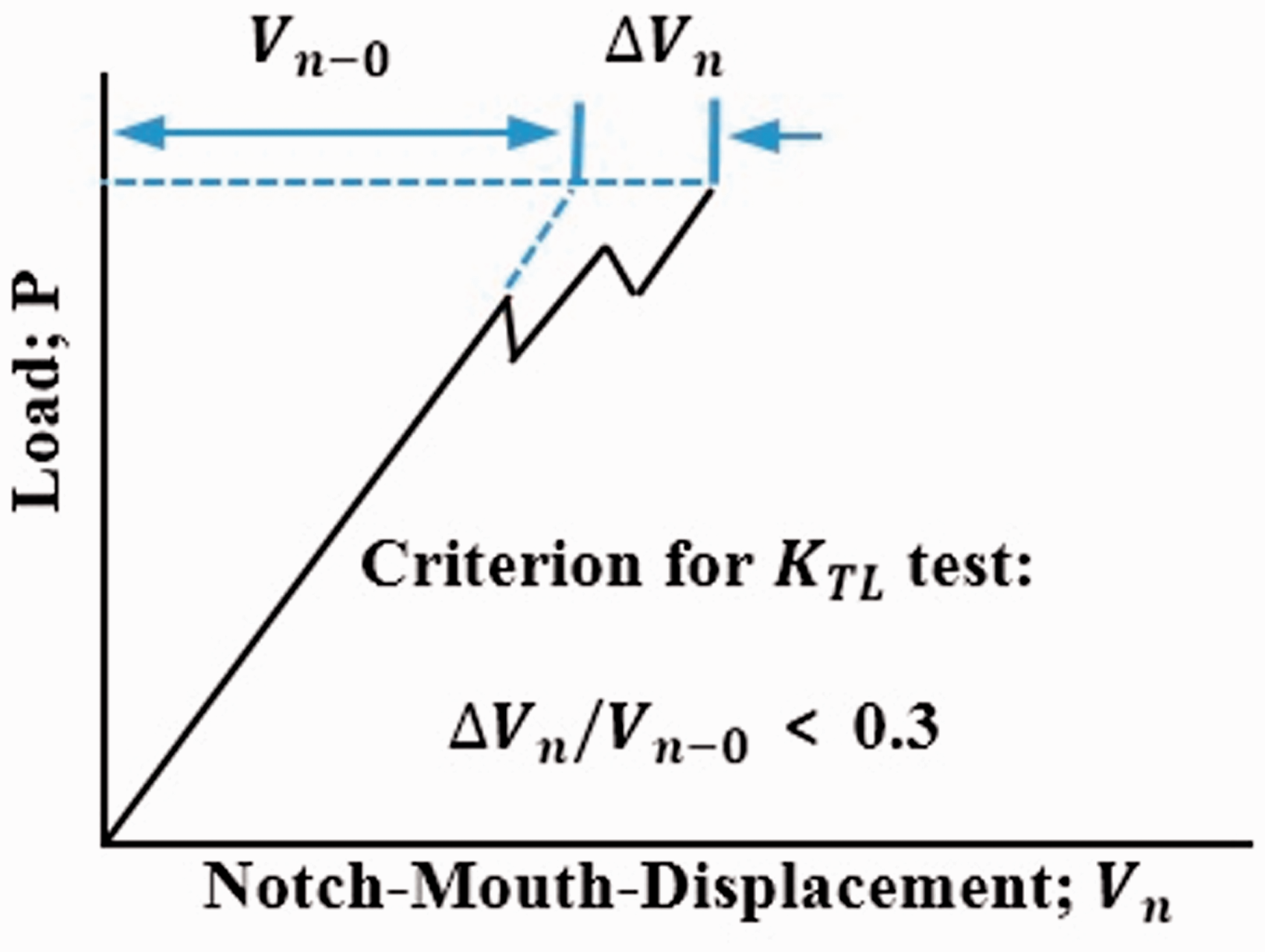
A typical curve of load variations versus notch-mouth-displacement extracted from ASTM E1922 [68].
The single-edge notches (i.e. pre-cracks) in modified compact-tension (CT) specimens suggested by ASTM E1922 [68] are created by utilizing a low-speed diamond wheel cutter. The
The bulk mechanical properties, namely the ultimate tensile strength, the trans-laminar fracture toughness, and the modulus of elasticity for 8-ply and 16-ply laminates are presented in Table 1. It should be noted that the average values of
Bulk mechanical properties of the quasi-isotropic composite laminates (8-ply and 16-ply).

By substituting the experimental values obtained from the load-notch-mouth-displacement curves into the mentioned criterion (
Another important point regarding the experimentally obtained curves is their linear behavior with negligible nonlinear portions, proving that the measured properties can be used in various brittle fracture criteria to predict the LPF load of the laminated composite specimens.
Fracture testing of quasi-isotropic laminates weakened by U-notches
For conducting fracture tests on U-notched laminated composite specimens, first, rectangular plates with the length of 160 mm and the width of 50 mm containing a central bean-shaped slit with two U-ends and the total length of 25 mm, are provided. Concerning the U-notched composite specimens fracture tests, three different notch root radii

The rectangular U-notched laminated composite component with its dimensions, parameters, and fiber orientations.
Considering the loading mode definition, it should be highlighted that it is fundamentally different for isotropic and orthotropic materials. For more clarity, consider a rectangular composite lamina with
For producing the laminated composite specimens containing U-shaped notches, first, two sacrificial plates are placed at the beneath and top of the laminates and then, a high-precision water-jet cutting machine is utilized. To polish the notches, as the cut surfaces, and also to reach smooth and defect-free notches, brass rods in a drill press with 25 µm lapping compound followed by 9 µm diamond suspension compound are used. Some of the prepared U-notched quasi-isotropic laminated composite specimens are shown in Figure 3.

Some U-notched quasi-isotropic laminated composite specimens tested in this research.
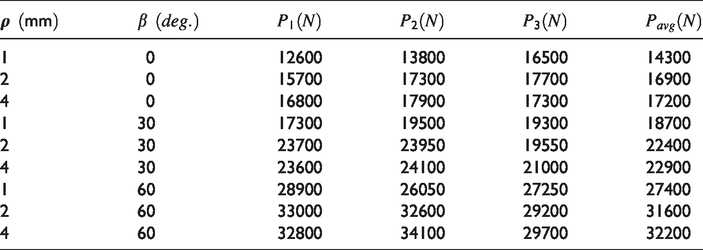
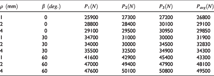
The experimentally obtained LPF loads of the U-notched composite specimens for 8-ply and 16-ply laminates are summarized in Tables 2 and 3, respectively. Considering the three notch root radii (i.e.
The experimental critical load results of LPF for the composite specimens with 8-ply laminate containing U-notches.
The experimental critical load results of LPF for the composite specimens with 16-ply laminate containing U-notches.
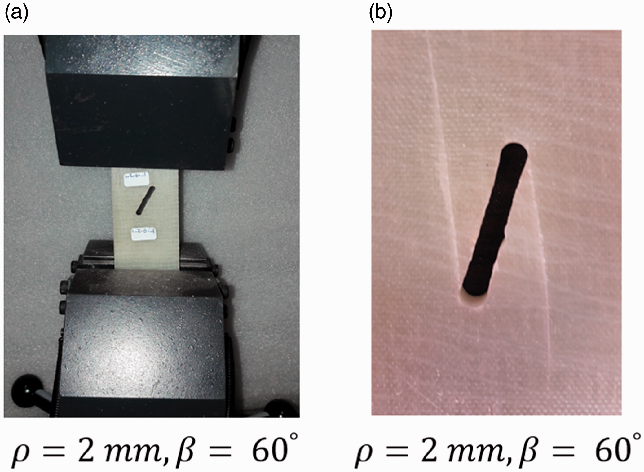
The U-notched laminated composite samples (a) during the experiment and (b) after failure.

The load-displacement curve for 16-ply quasi-isotropic laminated composite specimen with
The experimental procedure for the U-notched laminated composite specimens fracture tests is very similar to that for the un-notched specimens. The load is monotonically applied to the U-notched samples with a rate of 2 mm/min and the LPF loads are recorded by the universal tension-compression testing machine. As is obvious in Figure 6, the load-displacement curve is linear up to the LPF and a rapid fracture has occurred. The intermediate drop(s) caused by some plies failure do not affect the overall (i.e. the bulk) behavior of the load-displacement curves in their rising portions up to the LPF load. Therefore, it is intended to equate the composite laminates with some virtual isotropic brittle plates of the same dimensions for predicting the LPF loads of the U-notched laminated composite samples by employing brittle failure criteria developed in the context of LENFM.
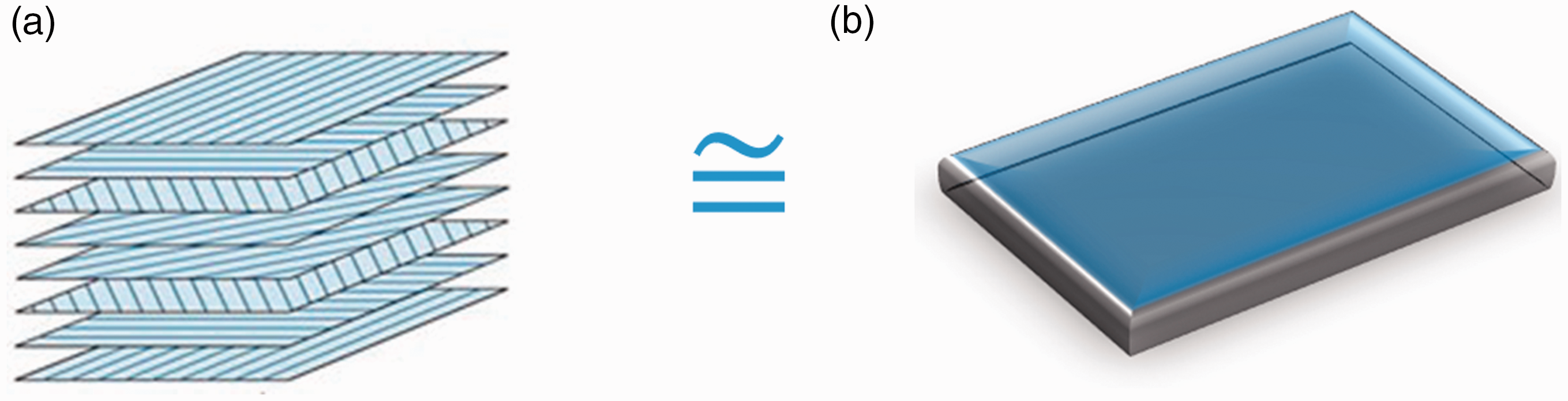
The scheme of Virtual Isotropic Material Concept. (a) Orthotropic composite laminate with Ex, Ey, Gxy, νxy, KTL, σ u ; (b) Linear elastic isotropic brittle plate with E, ν, KIC (or KC), σ c .
The virtual isotropic material concept
As widely reported in literature and with paying a careful attention to the bulk behavior of the tested U-notched composite specimens, the linear behavior of the load-displacement curves, either for the un-notched specimens or the U-notched specimens, is confirmed. This phenomenon is typicality of brittle and quasi-brittle materials, such as many composites based on epoxy resins reinforced by carbon or glass fibers etc. This quasi-brittle manner of the present laminated composite material makes it possible that the Virtual Isotropic Material Concept (VIMC) to be used by linking it to the linear elastic fracture mechanics (LEFM) criteria for predicting the LPF loads of the U-notched glass/epoxy composite specimens tested.
According to VIMC, the real laminated composite, having generally anisotropic behavior, is equated with a virtual brittle material, having isotropic behavior, for predicting LPF loads of the U-notched composite samples by utilizing the linear elastic notch fracture mechanics (LENFM).
It is worth noting that VIMC does not require conducting numerous experiments for identifying the longitudinal (
Figure 6 represents the VIMC schematically. As seen in Figure 6, a laminated composite material with several material characteristics, such as
Since the main aim of this investigation is the prediction of the last-ply-failure load of the U-notched laminated composite specimens, the ultimate load sustained by the notched laminated composite specimens should be determined. Thus,
Now, thanks to VIMC, the U-notched laminated composite samples are virtually considered as the isotropic brittle specimens, aiming to avoid layer-by-layer failure analysis or complex damage modeling for LPF load prediction.
Stress-based brittle fracture criteria
Maximum tangential stress criterion
The maximum tangential stress (MTS) criterion, originally proposed by Erdogan and Sih [54], is a famous method of brittle fracture analysis applied to engineering structures containing sharp cracks. According to this criterion, brittle fracture happens when the tangential stress 
Mean stress criterion
The mean stress (MS) criterion was first proposed by Wieghardt [73]. This criterion proposes that brittle fracture happens when the mean value of the tensile stress over a specified critical distance 
Ayatollahi and Torabi [74] have also proposed an extended form of MS criterion for predicting brittle fracture of rounded-tip V-notched specimens. According to this criterion, brittle fracture in a rounded-tip V-notched specimen occurs when the average of the tangential stresses
Now, according to the requirements of VIMC, the material critical stress 

Considering Table 1, the values of
As seen in equations (3) and (4), the critical distances rc and dc for the laminated composite material are achieved from the fracture test results under pure mode I loading and utilized under mixed mode I/II loading conditions for LPF load estimation of the U-notched samples. In other words, the critical distances rotate as rigid bodies at the notch neighborhood. This assumption has been frequently made by many researchers, e.g. Torabi and co-workers [59,64].
Combination of the FE analyses and VIMC for LPF load prediction
In order to implement the VIMC-MTS and VIMC-MS criteria for LPF load prediction of the U-notched quasi-isotropic composite specimens, two-dimensional (2 D) finite element (FE) isotropic models are created and analyzed under mixed mode I/II loading conditions. It is necessary to note that one of the advantages of VIMC is the independency of the LPF load prediction from the layer-by-layer modeling and analysis, and also the damage parameters computing of the notched laminated composites. Hence, the FE models are considered to be virtually made of the isotropic material under plane-stress conditions, due to the small thickness of the specimens compared to the length and width of them. The specimens are simulated and meshed with the eight-node plane-stress quadrilateral reduced-integration elements in the well-known commercial FE code ABAQUS 6.14. As mentioned earlier, the material properties of the isotropic model can be selected arbitrarily, because the fracture models are based on mechanical stresses, which are independent of the Young’s modulus and the Poisson’s ratio.
Figure 7 represents a typical mesh pattern for a U-notched rectangular specimen with the notch rotation angle (

A typical mesh pattern for the tested U-notched specimen with
Now, for predicting the LPF loads of the U-notched composite specimens in accordance with the VIMC-MTS criterion, first, an arbitrary tensile load (e.g. 2000 N) is applied to the upper edge of the simulated models, and the tangential stress at the critical distance
Since the analyses are perfectly linear elastic, the LPF loads predicted by VIMC-MTS criterion can be simply calculated as
The procedure of LPF load prediction of the U-notched composite specimens in accordance with the VIMC-MS criterion is the same as that explained above for VIMC-MTS criterion. According to the VIMC-MS, the average of tangential stresses over the specified critical distance
Therefore, the LPF load of the U-notched laminated composite samples tested under mixed mode I/II loading conditions can be calculated by VIMC-MS criterion as
Figure 8 represents the failure concepts of the VIMC-MTS and VIMC-MS criteria, schematically.

The failure concepts of (a) VIMC-MTS and (b) VIMC-MS criteria under mixed mode I/II loading, schematically.
One of the interesting aspects of VIMC is the independency of the damage initiation angle (DIA), i.e. the angle between the notch bisector line and the line drawn from the notch center of curvature to the point of damage initiation on the notch edge, from the type of material (i.e. orthotropic laminate or isotropic plate). This phenomenon causes that with increasing the notch rotation angle

Two failed U-notched laminated composite specimens subjected to (a) mode I and (b) mixed mode I/II loading conditions.
Also, Figure 9 suggests that the notch profile (herein U-notch) and the type of loading (i.e. mode I or mixed mode I/II with different mode mixity ratios) determine the DIA and most probably, it does not depend on the type of material. For more clarity about this phenomenon, a U-notched
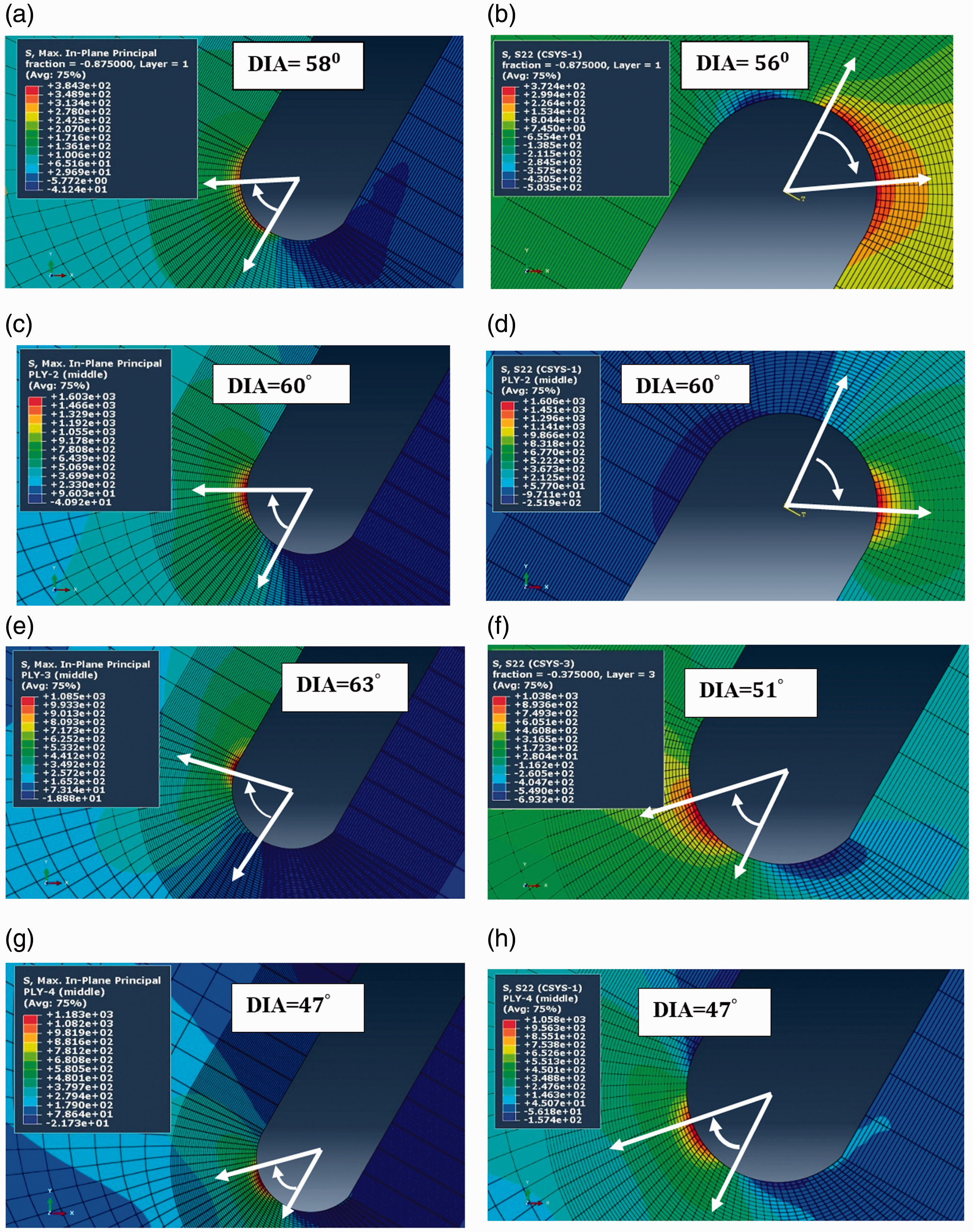
The principal and tangential stress contours for the U-notched composite specimen with

The principal and tangential stress contours for the U-notched composite specimen with
The maximum principal and tangential stresses in the two coordinate systems (i.e. off-axis and on-axis) are presented in Table 4.
The maximum principal and tangential stresses for the U-notched laminated composite specimen with

Some important points are essential to be explained about the FE results presented above.
First, it is evident that the maximum principal stresses in both off-axis and on-axis analyses are exactly the same. This equality shows that the values of principal stress are independent of any arbitrary user-defined coordinate system.
Second, the discrepancies between the maximum tangential stresses in off-axis and on-axis systems for layer 1 (
Another significant point is the rather small differences between the values of the maximum principal and tangential stresses in off-axis coordinate system, meaning that a great portion of the principal stress belongs to the tangential stress, regardless of the type of material, either orthotropic brittle composite laminate or isotropic brittle plate. So, utilization of the maximum tangential stress (MTS) and mean stress (MS) criteria for the present U-notched laminated composite specimens seems opportune. This finding confirms the validity of VIMC, since it considers the brittle composite laminate as a brittle isotropic plate, for which MTS and MS criteria are valid. These allegations are not valid from the viewpoints of continuum damage and progressive damage criteria, because according to these criteria, each laminate is considered as a number of laminas stacked on each other and the ply-by-ply failure evaluation is different for
At last, with careful consideration of the off-axis and on-axis pictures (see Figures 10 and 11), it is found that the DIAs regarding the maximum principal stresses are exactly equal and those regarding the maximum tangential stresses are approximately equal with a total difference of about 2-3%.
On the other hand, taking average from the DIAs of the entire plies presented in Figures 10 and 11 for off-axis and on-axis coordinate systems indicates that the average values are
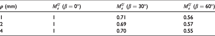
It was stated in Section 2 that the
Although changing the value of
The values of the mode mixity parameter for various loading angles and different notch tip radii.
It is necessary to stress again here that all of the statements and allegations provided in this manuscript are based on the bulk mechanical behavior of the U-notched quasi-isotropic E-glass/epoxy composite laminates tested, and the authors try to verify the validity of their own theoretical concepts with their own experimental observations and evidences. At the best of authors’ knowledge, no similar results are present in the literature from other researchers to be mentioned and discussed.
Results and discussion
As earlier mentioned, the theoretical results of the LPF load for the VIMC-MTS and VIMC-MS criteria are obtained from equations (5) and (6) and the experimental LPF loads recorded by the tensile testing machine are reported in Table 2. The variations of the experimental and theoretical LPF loads versus the notch root radius for various notch rotation angles are represented in Figures 12 and 13 for the laminates of 8-ply and 16-ply, respectively. Also, the discrepancies between the theoretical and experimental results for the U-notched laminated composite specimens are presented in Tables 6 and 7 for 8-ply and 16-ply laminates, respectively. It can be seen from Figures 12 and 13, and Tables 6 and 7 that both VIMC-MTS and VIMC-MS criteria are able to predict the LPF loads well for both the numbers of ply. The average discrepancies for VIMC-MTS and VIMC-MS criteria are obtained equal to 11.7% and 11.5%, respectively.
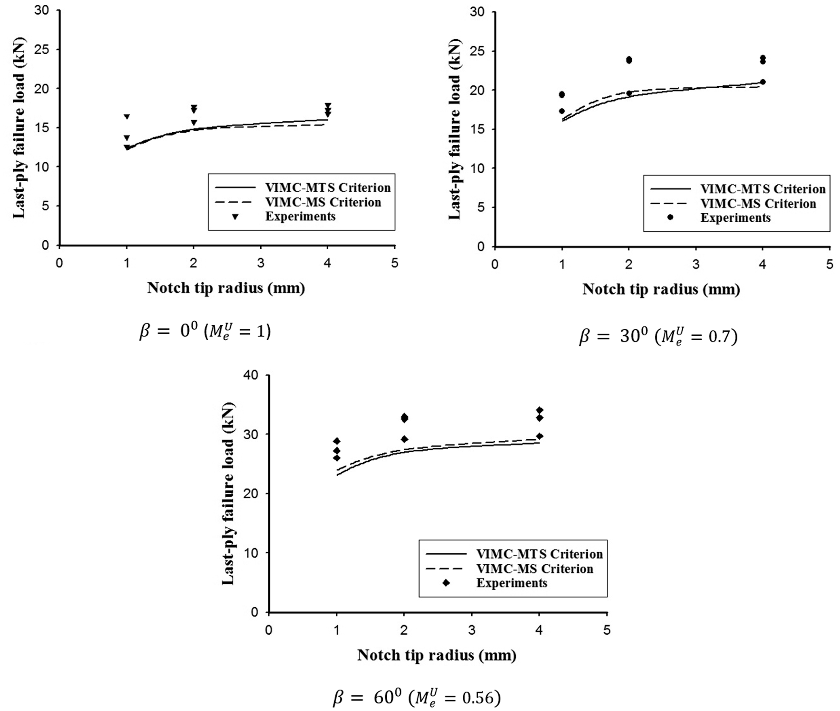
Variations of the LPF loads of the U-notched 8-ply quasi-isotropic laminated composite specimens versus the notch root radius for the two combined criteria and the experimental data.

Variations of the LPF loads of the U-notched 16-ply quasi-isotropic laminated composite specimens versus the notch root radius for the two combined criteria and the experimental data.
The discrepancy values obtained from comparing the theoretical and experimental results for 8-ply laminated composite specimens containing U-notches tested under mixed mode I/II loading conditions.

The discrepancy values obtained from comparing the theoretical and experimental results for 16-ply laminated composite specimens containing U-notches tested under mixed mode I/II loading conditions.
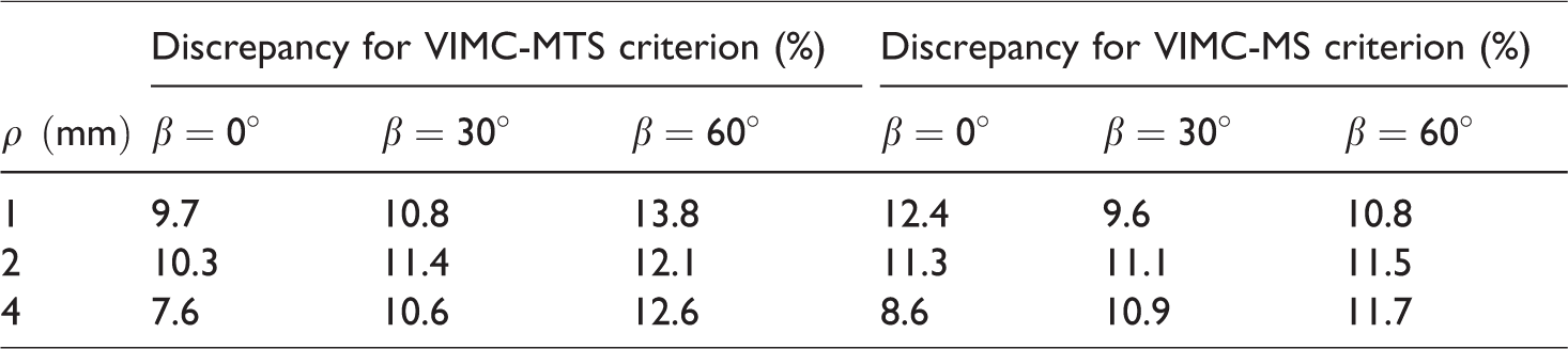
These discrepancies indicate that both criteria are powerful in predicting the load-carrying capacities (LCCs) (i.e. LPFs) of the U-notched glass/epoxy composite laminates tested under mixed mode I/II loading conditions. Since the predictions obtained from the new concept have high performance for different numbers of ply and various mode mixity ratios, it seems that the two combined stress-based approaches are independent of material properties for the glass/epoxy laminate. This claim is also clear from the FE analyses, which are based on the stress distribution analyses, regardless of each lamina properties.
As shown in the previous sections, the mixed mode I/II loading in U-notched composite laminates is defined the same as that in U-notched isotropic plates. What is the reason? This is an important question, which should be answered. As an answer, it is worth mentioning that because VIMC equates the laminated composite material with an isotropic plate, the U-notched isotropic specimens are evaluated for failure instead of the U-notched laminated composite specimens. Hence, thanks to VIMC, it is allowed to utilize the definition of mixed mode I/II loading also in the U-notched composite laminates. By increasing the
Although the LPF load prediction of the U-notched laminated composite specimens under mixed mode I/II loading conditions is the main goal of this investigation at the macroscopic level, the microscopic investigation of the damage zone at the notch neighborhood is also useful to better recognize the failure modes and damage mechanisms. To this aim, several micrographs are taken from the damage zone by means of the scanning electron microscope (SEM) and interpreted. Visual observations during the fracture tests are also reported and discussed.
Figures 14 and 15 represent the shapes and modes of damages created in the periphery of U-notches at the macroscopic and microscopic levels, respectively. Figure 14 depicts two damaged U-notched quasi-isotropic laminated composite specimens tested under pure mode I and mixed mode I/II loading conditions. At the first glance in Figure 14(a) (i.e. pure mode I loading conditions), two vertical lines are seen in the vicinity of U-notch root in both sides of the damaged area. However, these formed lines are not exactly vertical and in fact, they are oblique lines propagating towards the up and bottom of the tested specimens. After forming the longitudinal cracks (i.e. the oblique lines), the damage zone spreads across the horizontal axis of the specimens as a result of increasing the applied load. It is worth expressing that the splitting phenomenon is caused by two major sources, namely the fiber/matrix splitting produced by weak fiber/matrix adhesion and the notch-induced splitting [75] created as a result of stress concentration of notch. Because the procedure of specimen fabrication is followed precisely and also the tests are carried out properly, the bundle of the longitudinal and transverse cracks (i.e. splits) created ahead of the U-notches is the notch-induced splits (NISs).
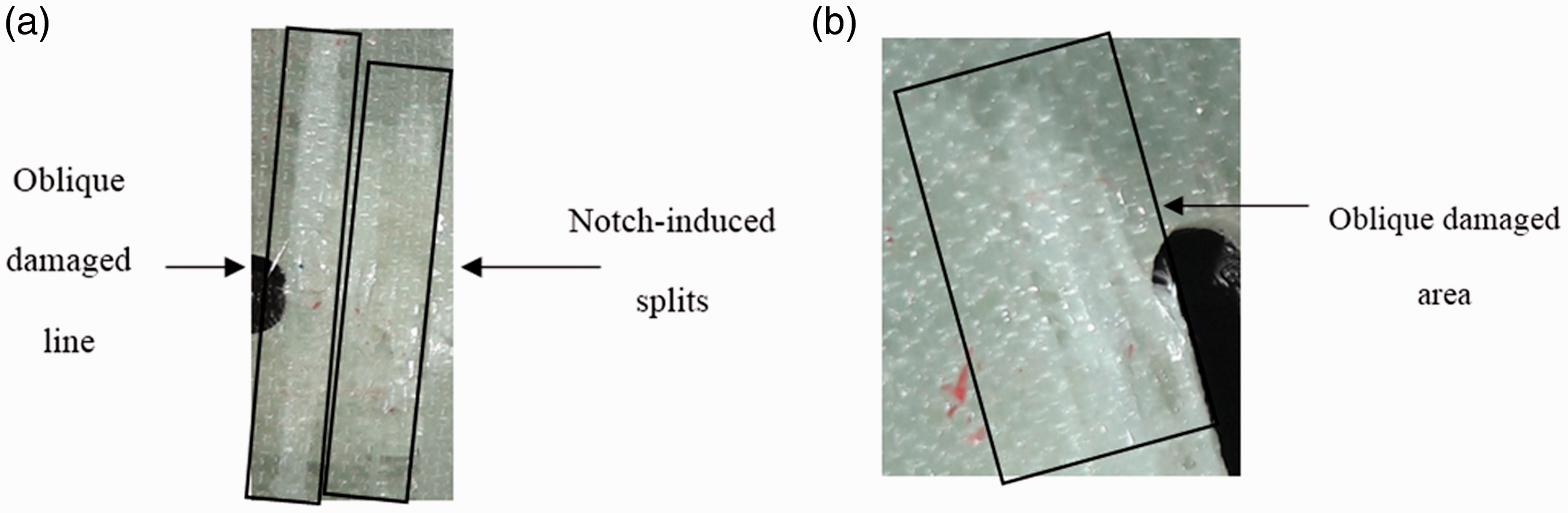
The damage zone around the notch border for (a) mode I loading and (b) mixed mode I/II loading.

Two SEM micrographs taken from the damage zone of the U-notched quasi-isotropic laminated composite components; (a) mode I loading and (b) mixed mode I/II loading.
Figure 14(b) shows the oblique damage area, regarding mixed mode I/II loading that may be caused due to two important reasons. First, the lay-up configuration tested contains ±
For better recognizing the damage mechanisms, some SEM micrographs are taken from the fracture surfaces of the specimens. Figure 15 shows two samples of such SEM micrographs for the damage surfaces of the U-notched laminated composite specimens under mode I and mixed mode I/II loadings. It is seen in Tables 2 and 3 that for a particular notch root radius, by increasing the notch rotation angle
Another viewpoint of increasing the LPF load under mixed mode I/II loading is depicted in Figure 15. As shown in Figure 15(a), the dominant mode of failure, which is seen simultaneously with the LPF load record, is the fiber breakage associated with the fiber pull-out. As mentioned in previous paragraph and shown in Figure 15(b), several bands develop along the direction of the maximum shear stresses in some laminas, called the shear bands. By comparing the two SEM micrographs, the influence of shear stresses on the formation of the shear bands by increasing the contribution of mode II loading in mixed mode I/II loading conditions is obvious. In other words, as the loading type varies from pure mode I towards mode II, the matrix micro-cracking and the fiber-matrix interfacial failures within the damage zone near the notch edge become more visible, demonstrating more energy absorption during the fracture process.
Conclusions
The outcomes of this study can be summarized as follows: A new set of experimental results regarding the last-ply-failure (LPF) of U-notched quasi-isotropic E-glass/epoxy composite laminates under tension-shear loading were provided for verifying the validity of the most recently proposed concept, namely the virtual isotropic material concept (VIMC). Further experiments are also essentially needed to show the effectiveness of this newly born concept for laminated composites with different lay-up configurations and various fiber/resin pairs. It was shown that VIMC could be well combined with the MTS and MS criteria, which are fundamentally two brittle fracture criteria for isotropic materials, for estimating the LPF loads of the U-notched composite laminates tested. By means of the VIMC-MTS and VIMC-MS criteria, the LPF load prediction was rapid and convenient with no need for the time-consuming ply-by-ply failure analysis. No meaningful difference was found between the estimations of VIMC-MTS and VIMC-MS criteria. Thus, VIMC-MTS criterion is preferable in mechanical design of notched composite structures due to its significant simplicity. Macroscopic analysis of the composite specimens failed indicated that the notch profile, as well as the combination of tension and shear deformations (i.e. the mode mixity ratio) determine the location of damage initiation on the notch border in the U-notched composite specimens. Therefore, it is strongly believed that the type of material, e.g. isotropic, orthotropic, quasi-isotropic etc. cannot affect this important factor. The SEM micrographs taken from the vicinity of the damaged U-notches indicated that the major failure modes in the notched composite samples tested were the matrix micro-cracking due to concentrated shear deformations and of course, the fiber breakage.
Footnotes
Acknowledgement
The authors would like to thank Mr. Hamid Reza Majidi for performing a fine tuning on the manuscript text.
Declaration of conflicting interests
The author(s) declared no potential conflicts of interest with respect to the research, authorship, and/or publication of this article.
Funding
The author(s) received no financial support for the research, authorship, and/or publication of this article.