
Abstract
For the high cost of aramid fibres and the necessity for finding alternatives which are environmentally friendly, a portion of aramid was substituted by woven kenaf at various sequences and thicknesses, to identify the proper arrangement for producing helmet shell. Drop-weight impact tests were conducted on different configurations of 19 layers of kenaf and aramid reinforced polyvinyl butyral film, which were fabricated by the hot press method. Effects of fibre content, layering sequence and energy absorption of the laminated composites were studied at three different impact energies 50, 75, 100 J. Results suggested that the behaviour of hybrid laminates has a positive effect in terms of energy absorbed and impact resistance, due to lower failure strain of kenaf fibres. Additionally, placing woven kenaf layers alternate with aramid layers provides higher impact loads and absorbed energy than placing woven kenaf and aramid separately, especially at impact level 100 J. For example, the absorbed energy of the 17 Aramid/2 Kenaf Alt. (H1A) is 72.99 J, while for 17 Aramid/2 Kenaf (H1) is 66.04 J. The closed curves indicated the success of the samples in absorbing the dissipated energy at various impact energies values. It could be deduced that it is possible to replace the aramid fibre in various composites industries by kenaf fibre, to minimize harmful environmental effects and cost of petroleum products.
Introduction
Low velocity impact is identified as an impact event where the time of the impactor in contact with the sample exceeds the period of the lowest vibration mode such as a dropped tool (<30.48 m/sec). In order to describe the low velocity impact response, the boundary conditions of the structural component are significant parameter. The effect of low velocity non-penetrating impact is like that of a dropped tool, careless handling, or runway debris. This type of damage is most often undetectable by visual surface inspection [1], and can cause a significant reduction in the material properties. Toughness is an essential property of composite materials and shows the energy absorption capacity of the specimen [2]. The low-velocity impact test is necessary to optimize designing these materials which used in the vast majority of fields such as construction structures, building, automotive, military, aerospace, biomedical materials [3]. The most critical damage caused by low-velocity impact tests consists of holes and cracks in composites, which may reduce the composites’ strength [4]. While Studies on high-velocity impact focus on fracture and fragmentation [5].
Varying methods of low velocity impact tests for composites have been used in the literature. The drop weight impact testing machine has the ability to simulate closer to real-life impact conditions. An impactor of specific weight is dropped from a predetermined height. By recording the rebound velocity of the impactor with optical sensors, energy can be measured through the different stages of specimen fracture. Unlike Charpy and Izod impact tests, the drop weight test allows for a greater variety of specimen geometry [6].
Owing to notable properties, sustainability concept and environmental awareness, hybridize natural with synthetic fibres to fabricate hybrids have been rapidly gaining market share in many applications (structural, military, aerospace and automotive vehicles) [7]. Kenaf fibres and Polyvinyl Butyral (PVB) has adopted an environmentally-friendly corporate policy, for reducing greenhouse gas emissions, and introduced innovative solutions for the sustainable, more responsible use of natural resources [8]. However, researchers are still continuously embarking on the possibility of using natural fibres due to their disadvantage which could be decreased by hybridising with synthetic fibres [9].
There are a few studies have focused on the drop weight impact properties of hybrid synthetic/cellulosic fibres reinforced composites, including the effect of laminate configuration and manufacturing procedure. Nisini et al. [10] have studied the drop-weight impact testing of hybrid carbon/basalt/flax composites with a varied stacking sequence of basalt and flax fibres composite. It has been shown that the alternating stacking sequence, (carbon-flax-basalt-flax-basalt-flax-carbon), in comparison with (carbon-basalt-flax-basalt-carbon) shows a higher standard deviation of the single specimen values. The interest and evaluation of high performance materials, manufactured from kenaf fibre hybridization with Kevlar fibre, are growing in recent years. Ou et al. [11] evaluated the use of Kevlar fibre reinforced with wood-flour/high-density-polyethylene composites, to enhance the mechanical characteristics of that material. It can accordingly be concluded that the addition of a small amount (2–3%) of Kevlar fibres can be used as a reinforcement to improve the strength and toughness of the hybrid. In another study, Kamardin et al. [12] have investigated the mechanical performance of hybrid Kevlar/kenaf powder reinforced polypropylene composites, in 20 to 40% weight ratio of kenaf powder. It was observed that hybridization effects provided improved mechanical properties for this hybrid structure. While Malingam et al. [13] have investigated three different configurations of kenaf and Kevlar fibre reinforced polypropylene hybrids under impact energies 10, 20 and 30 J. The results indicated that the hybrid showed a positive hybrid effect in which they demonstrated higher penetration resistance, compared to the kenaf composites, a balance between the mechanical strength and the environmental issues could be achieved by hybridization. To preserving natural fossil resources, Ismail et al. [14] have evaluated hybrid composites of 75% glass and 25% kenaf fibres reinforced composites under low impact velocity loading. They have concluded that the absorbed energy increased with the increase in incident impact energy.
Roy et al. [15] have studied the mechanical behavior of the neat and NR latex coated single and two layered of p-aramid and ultra-high molecular weight polyethylene (UHMWPE) fabrics in terms of impact resistance. Results showed superior impact performance due to the improved bonding between the layers leads to improve the impact performance of NRcoated p-aramid samples. In another study, Roy et al. [16] have identified the energy absorption of different modes of impact for two-layered stitched, NR- p-aramid soft composite and Epoxy- p-aramid stiff composite; with reinforcement to matrix ratio 90:10 and 40:60 for flexible and stiff composites, respectively. It was concluded that the p-aramid based soft composite is more suitable than p-aramid based stiff composite for protective applications. Majumdar et al. [17] have used the p-aramid fabrics with three different levels of thread densities, synthesized using silica nano-particle and polyethylene, in soft body armour panels. It was concluded that it is possible to reduce the weight of the panel by 23% after treatment and the energy absorption increased with the increase in thread density in the fabric.
This study aims to evaluate the drop weight impact behaviour of different laminated composites arrangements of kenaf and aramid stacking sequences at three impact energy levels. In addition, results were compared with pure kenaf composite and pure aramid composite, with an indication of the most appropriate layering arrangements. Furthermore, an optical microscope has been used to investigate the damage mechanisms.
Experimental
Materials
Two types of woven fabrics were used: plain woven kenaf and Aramid fibres double side coated with 12% weight PVB phenolic, as shown in Figure 1. Table 1 lists the physical characteristics of plain woven kenaf, supplied by ZKK Sdn Bhd, Malaysia. PVB-phenolic is a member of vinyl polymers with the addition of 5% phenolic. PVB film is one of the most popular interlayer used for laminated safety glass, commonly used in the automotive and architectural fields bonded between two panels of glass. The polymer interlayer of PVB is tough and ductile, mostly used for applications that require strong binding, adhesion to many surfaces, toughness and flexibility. It has very good bonding between the aramid and kenaf fibres, the stress redistribution from the PVB film to the fibres takes place through its bond/interphase. It has low cost, easy fabrication, long lasting, and good mechanical and chemical properties [18]. More recently, the matrix-film laminating method is developed as a new production method; it is simpler and more economical than the matrix resin dipping method. The PVB physical properties are; anti-UV, antioxidant, sound proof, heat protection, safety, better adhesion and resistance to impact.

Plain Woven (a) Aramid fibres coated with PVB -phenolic, (b) Kenaf fibre and (c) PVB film.
Physical and mechanical properties of materials (technical sheet).

Hybrid composite fabrication
The hot hydraulic press technique was used to fabricate hybrid laminates of different kenaf fibre weight content with PVB film and aramid fabric coated with PVB-phenolic film, as shown in Figure 2. Table 2 illustrates the various configuration layers and stacking sequences of the hybrid laminates. In order to reduce the number of aramid layers and to identify the effect of layering sequence, plain woven kenaf layers were placed in twelve different locations. Studies are also carried out on 19 layers of aramid/PVB-phenolic composite and plain woven kenaf/PVB composite for the purpose of comparison.

The hybrid composite specimens prepared using the hot press technique.
Specifications of the laminated hybrid composites.

Figure 3 illustrates an example of fabricating hybrid H5 and H5A. 11 aramid layers, 8 kenaf layers and 9 PVB film layers cut in the same size (100 × 150 mm sheets) and then arranged in different stacking. To fabricate a rectangular flat laminated hybrid H5 panel, the 11 coated aramid/PVB phenolic layers arranged together then the PVB film layers stacking between 8 woven kenaf layers. While in hybrid H5A, the 11 coated Aramid layers stacking alternatively with 8 kenaf and 9 PVB layers. Consequently, H5 and H5A have same aramid, kenaf and PVB layers number but with a different arrangement. A mould release agent was sprayed on the mould surfaces before any moulding process to prevent adhesion as well as to obtain a smooth sample surface. The stacks of 19 layers of different laminates were centered between two stainless-steel moulds and hot plates of a compression moulding press. Subsequently, the platens were closed, the hot press plates were heated to 165 °C for 20 min, and the compression pressure was set to 5 MPa. Once the temperature of the platens reached 165 °C, the compression pressure was increased to 8 MPa and held constant for 15 min. After this compression cycle, the platen temperature was reduced to room temperature (25 °C), while the pressure was maintained at 8 MPa until the temperature reached 25 °C. Once the platen temperature reached 25 °C, the hybrid composite laminates were taken out of the compression moulding frame. The dimensions and mass of the hybrid laminates were measured to calculate the density and the areal density of the hybrid materials.
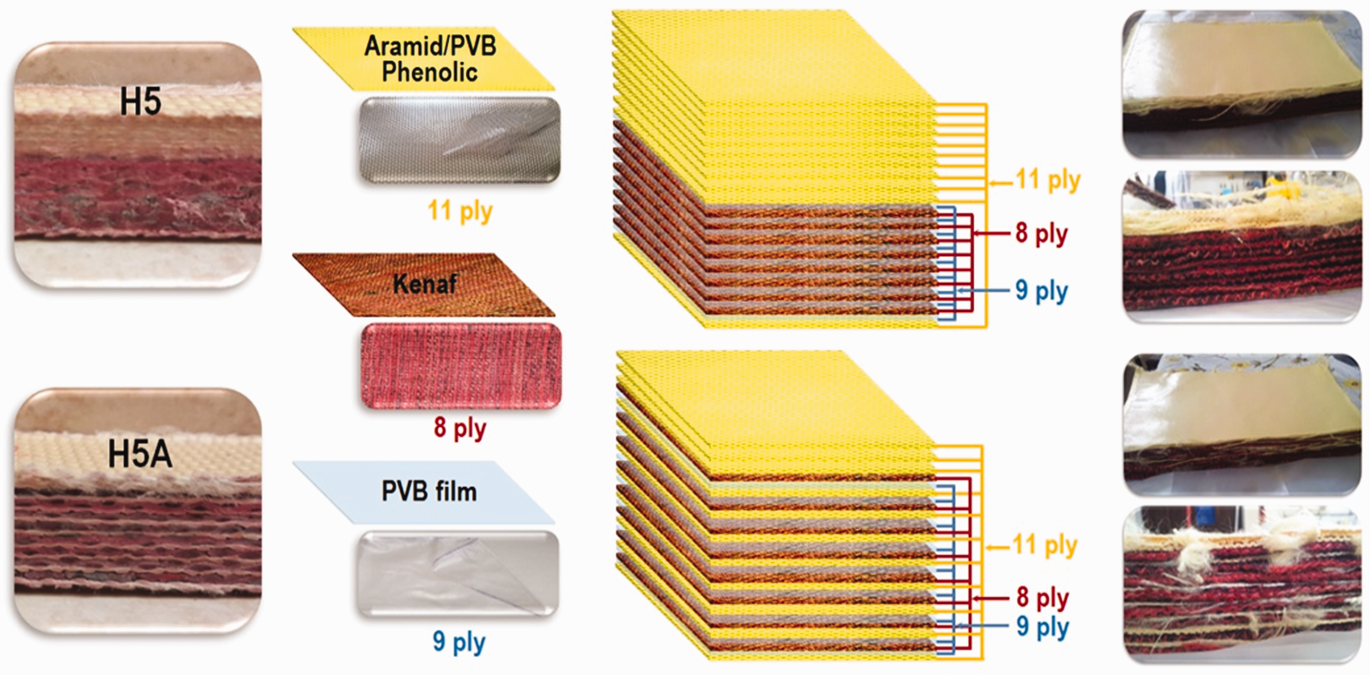
Hybrids H5 and H5A stacking sequence.
Drop weight impact test
Composites are usually subjected to various loading conditions and susceptible to fail by an impact load of foreign objects during their service life. The low-velocity impact is one of the most critical in particular for composite structures because it involves internal damages, like tool drops or even foreign objects. Low-velocity impact damage causes delamination which could reduce the structural integrity of the composite materials significantly and most often lead to a sudden failure while the surface of the composites might be appeared undamaged by visual inspections. An understanding of the effect of low-velocity impact damage is important in fibre reinforced composites [19]. The effect of these internal damages on the impact strength of the composite could be determined using drop weight impact test machine, according to the ASTM D 7136 [20]. The drop weight impact tests, at three different energy levels, were conducted by using a drop-weight device. A stainless steel impactor of 5.101 kg weight with a hemisphere nose of 12 mm diameter is dropped from a predetermined height, then the energy is calculated by recording the rebound velocity of the impactor with optical sensors. The drop heights of the impactor were adjusted to generate incident impact energies. Impact energy is the gravitational potential energy of the impactor right before contact with samples takes place, calculated using equation (1):
The first energy level 50 J was obtained by placing the mass at the 1 m height position and dropping it freely. To obtain 75 J and 100 J, the mass was placed at the 1.5 m and 2 m height position, and dropping it freely. The samples were firmly fixed at all edges using annular clamps and were impacted for one time; a catcher mechanism was activated to prevent a second strike. Then the sample was kept on the support with an adjusted position so that the impact point was located in the center of the specimen. The drop weight test allows for measuring the force versus time response, makes possible the study of the energy absorption through the different stages of samples fracture [1]. The absorbed energy is the energy dissipated in laminated hybrid material, can be calculated from force-displacement curves as the area enclosed within the curve. Three test samples were performed at each drop height for each composite configuration type. Figure 4 shows the drop weight impact specimens and the drop weight impact machine.
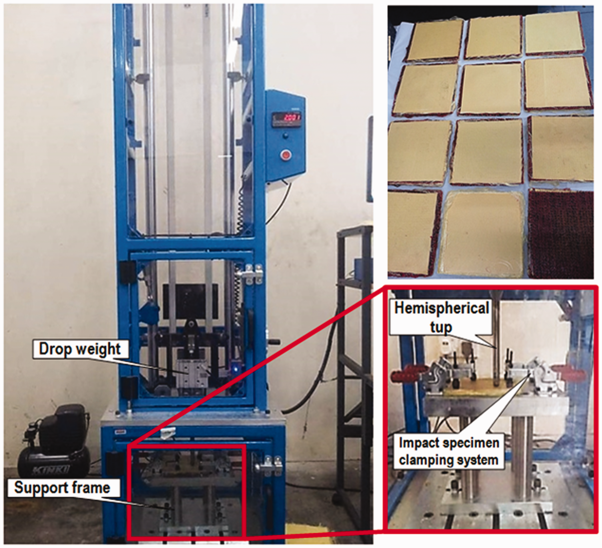
Overall view of the drop weight impact machine with impactor load cell and support fixture.
Damage mechanisms
The damage mechanisms were investigated using an optical microscope and optical pictures.
Results and discussions
All hybrids impacted specimens exhibit a non-linear behavior increase with a large displacement, at all energy levels. However, in all sample curves; multiple oscillations before the peak load have been observed, decreased when the percentage of kenaf layers increased. This behavior was attributed to the condition when the impactor contact with the sample, initiating damage in the material with different reinforced frequencies which results in unpredictable vibration behavior under impact loading. The impact energies were not enough to produce the penetration in the hybrids; therefore drop weight impact resulted in striker rebound. Hence, there was no local indentation was revealed on the impacted surface. Meanwhile, there were no cracks, obvious signs of delamination and fibre fracture can be observed on the bottom surface of composites. Razali et al. [21] mentioned that, as the plate sample thickness continued to increase, the damage on the lower skin decreased, which could not be seen.
Contact force vs. displacement curves show closed loops, characterize the impact behavior of composite laminates and usually represent their impact properties. The maximum load that the composite can bear before undergoing damages can also be obtained from these curves (peak load). So the comparisons between different materials could be done to characterise the laminate resistance to impact loads. Furthermore, absorbed energy can be calculated from the areas enclosed by the load–displacement curves, at each energy level. It is evident that the area under the curves increases with the increment of the impact energy levels, indicating an increase in the absorbed energy.
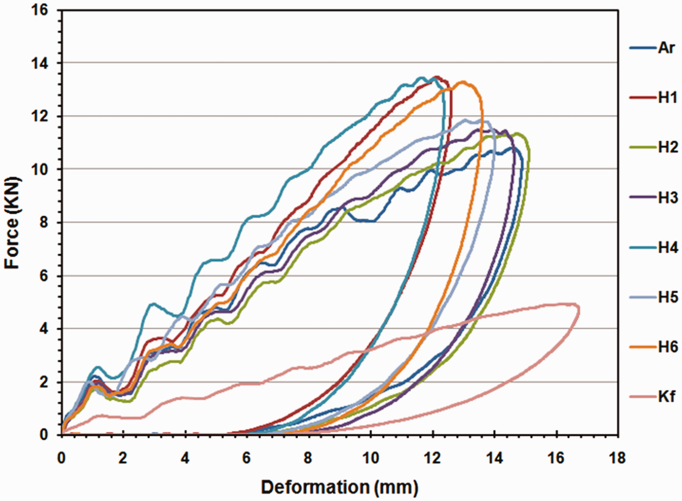
The load-displacement curves for all laminated composites, at 50 J impact energy levels are shown in Figures 5 and 6. It can be observed that by increasing the kenaf fibre content, the composites bear the load up to a higher deflection and failure occurs in a ductile manner. Although these data depend on the content of fibres in the composite, it also depends on the thickness of the samples. They show that hybridization with kenaf fibres is comparable to aramid fibres in terms of impact resistance in reinforced composites. When the impactor contacts the surface of the laminate, the stress waves spread through the neighbouring ply within the laminate. The experimental results show that both sample thickness and stacking sequence are two of the main parameters involved in impact phenomena.

Hysteresis cycles for drop weight impact force–displacement curves of kenaf, aramid composites and their hybrids at 50 J.

Hysteresis cycles for drop weight impact force-displacement curves of alternative layers of kenaf, aramid composites at 50 J.
The effect of stacking sequence layers of hybrid composite materials in the load–displacement curves is shown in Figure 7. It was found that the response of laminated samples to drop weight impact is significantly affected by the stacking configurations of the hybrid laminates. The maximum value of impact loads tends to increase when placing woven kenaf alternatively with aramid fabric layers more than placing woven kenaf together and aramid layers separately. Alternative kenaf with aramid layers tends to take up the stresses and to distribute them evenly throughout the hybrid which enables to increase the maximum load. In contrast, the presence of placing woven kenaf together and aramid layers separately involves a considerable improvement in energy absorbed value. Alternative kenaf/aramid stacking sequence implies also a change in the deformation values which appears to be higher than deformation values for placing woven kenaf together and aramid layers separately. Similar results were being reported by [22]; it was found that the various stacking sequences of the layers showed a drastic change in the impact performance.

Hysteresis cycles for drop weight impact force-displacement curves of each hybrid and its alternative laminate at 50 J.
Figure 8 shows the peak impact load with the impact energy for all laminated hybrid composites at 50 J. It shows that the peak load vary much within all laminated composites. Among all laminated composites, the strongest one is Ar composite and the weakest one is the pure kenaf composite (Kf). Hybrid samples with placing woven kenaf together and aramid layers separately show the lowest peak load. While hybrid samples with placing woven kenaf alternate with aramid fabric layers show the highest peak load. This trend is due to the fact that the symmetrical sample configuration (when using the same fibre), have responses compatible with symmetric loading. When the sample structure is symmetric (dimensional stability), the load can uniformly distribute along with the laminated layers. For the same hybrid volume and thickness, using alternative configuration layers tend to be more symmetry feature which increases the stiffness and strength. Furthermore, the differences in peak impact load are due to variation in the elastic property of the hybrid laminates. At the same time, all hybrid laminates exhibit a residual elastic response; the displacement returns toward the axis origin during unloading. It means that some of the elastic energy is recovered by the fibre geometry of hybrid materials.
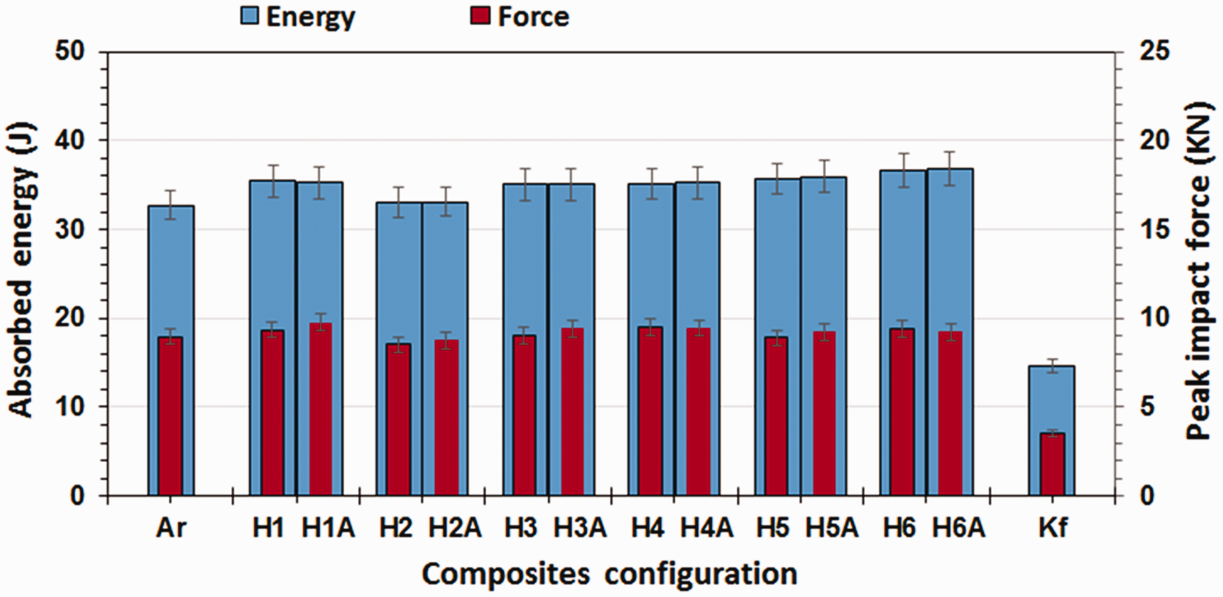
Drop weight impact parameters of all hybrid laminates, peak impact force and absorbed energy at 50 J.
While the highest maximum force is offered by the H1 and H1A, the largest energy is absorbed during impact on the hybrid H6 and H6A. The fact that the hybrid composites displayed higher impact values than the pure aramid composites is not uncommon. Researchers have found that by incorporating small percentages of low-modulus fibres is an effective means of increasing the impact performance of composites [23]. This was attributed to the fact that laminates offered superior impact resistance due to increased material plasticity and flexibility of the composite. In addition, Razali et al. [24] mentioned that, as the plate thickness increased, the impact energy increased relatively. Hybrid H3 and H4 demonstrated very close behaviour in terms of the final energy absorption, whose final energy absorption difference is 0.1 J. Besides, Hybrid H5 and H6 are showing the same close behaviour, which differs in energy absorption is 0.9 J. The increase in kenaf content up to three layers seems to positively affect the absorbed energy, while it appears to be less influent on the maximum load. This finding can be ascribed to the higher void content due to the difficulty in impregnating increasing amounts of kenaf fibres.
A similar finding was also observed in the average impact force of all laminated composites, as shown in Figures 9 and 10. Generally, it was clear that impact force and absorbed energy increased as the impact energy level increased, for all laminated composites. The Ar curve showed rapid fluctuations due to higher friction between the impactor and aramid fibres restrict the mobility of the composite upon impact. As reported by many studies [25,26], the sudden drop in contact force right after the peak load indicates the occurrence of cracking. After that, the load decreased following almost a linear and nonoscillating curve.

Hysteresis cycles for drop weight impact force–displacement curves of kenaf, aramid composites and their hybrids at 75 J.

Hysteresis cycles for drop weight impact force-displacement curves of alternative layers of kenaf, aramid composites at 75 J.
At low impact energy (50 J), the results of the impact performance show that hybridization and variation in kenaf/aramid fibres content do not have a big change. With increasing impact energy, the impact performance becomes more and more dependent on the content of kenaf and aramid fibres [27].
The effect of stacking sequence layers of hybrid composite materials in the load–displacement curves is shown in Figure 11. It was found that the response of laminated samples to drop weight impact is significantly affected by the stacking configurations of the hybrid laminates. The maximum value of impact loads tends to increase when placing woven kenaf alternatively with aramid fabric layers more than placing woven kenaf together and aramid layers separately. In addition, the presence of placing woven kenaf alternatively with aramid fabric layers involves a considerable improvement in energy absorbed value. Alternative kenaf/aramid stacking sequence implies also a change in the deformation values which appears to be higher than deformation values for placing woven kenaf together and aramid layers separately. As confirmed by experimental results, the laminate configuration heavily affects the hybrid response, as reported in other studies [28]. Aramid laminates exhibit a lower displacement, whilst kenaf and hybrid laminates, being more compliant, absorb energy through the deformation.

Hysteresis cycles for drop weight impact force-displacement curves of each hybrid and its alternative laminate at 75 J.
Figure 12 shows the variations in peak impact load and energy absorbed by the impacted samples at 75 J. It can be seen that there is an increase in the total peak impact load and energy absorption for all laminated composites. The highest maximum force and absorbed energy are offered by the H1A during impact at 75 J. Although much less energy is absorbed by Kf composite compared to the other laminated composites, the reinforcing effect over hybridizing with aramid is significant. The total energy absorbed by the aramid composite is 53.11 J, which is almost same as the total energy absorbed by H2 hybrid. Hybrid H4 and H5 demonstrated very close behaviour in terms of the final energy absorption, whose final energy absorption difference is 0.1 J. In this Figure, a slight increment in the absorbed energy can be seen for all laminated composites. While much less energy is absorbed by pure kenaf composite at 75 J energy levels. Furthermore, the total peak impact load and energy absorption of all laminated composites showed almost the same behavior when tested with a 50 J energy level. This is in quite agreement with the results being reported previously [2,14]. In low energy levels, all energy was absorbed by the samples and the samples do not completely failed. As a consequence, it leads the absorbed energy value is almost same.

Drop weight impact parameters of all hybrid laminates, peak impact force and absorbed energy at 75 J.
With increasing impact energy, the impact performance becomes more and more dependent on the content of aramid and kenaf fibres. In the case of 100 J impact energy levels, the load-displacement curves for all laminated composites show a sudden drop in peak load with a prolonged plateau region, as represented in Figures 13 and 14. This indicated that the deformation was reached the kenaf layers, specifically when the kenaf fibres content increased. By increasing the kenaf fibre content, the composites bear the load up to a higher deflection and failure occurs in a ductile manner. The impact behavior of all laminated composites exhibited a high difference in accordance to maximum impact load, while the average absorbed energy of all laminated composites showed almost the same behavior when tested at 100 J energy levels. As stated by others [29,30], the impact properties of the laminated composite were accountable for deciding the impact resistance of composites. This implies that both the effect of interlaminar and interfacial strength between the layers highly decide impact properties, especially in the case of weaving pattern as stated by researchers [31].
Hysteresis cycles for drop weight impact force–displacement curves of kenaf, aramid composites and their hybrids at 100 J.
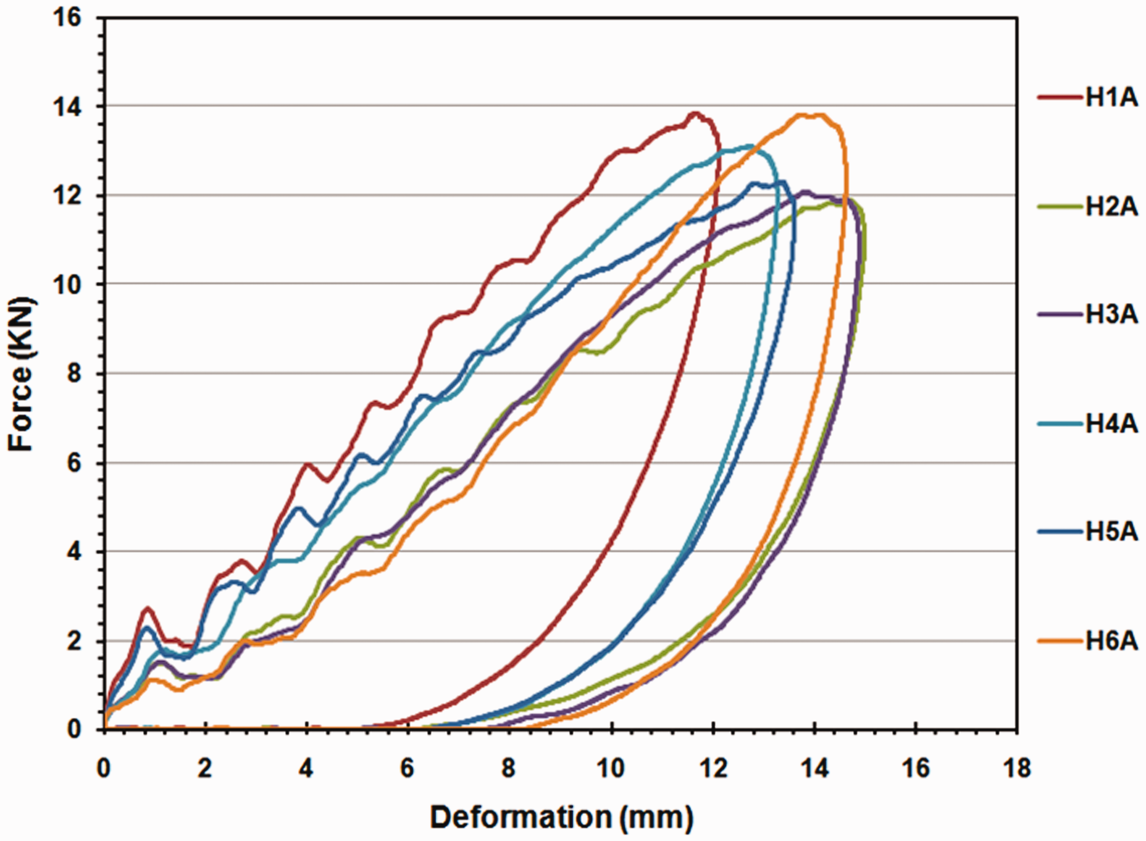
Hysteresis cycles for drop weight impact force-displacement curves of alternative layers of kenaf, aramid composites at 100 J.
The effects of stacking sequence layers of hybrid composite materials in the load–displacement curves are shown in Figure 15. It was found that the response of laminated samples to drop weight impact is significantly affected by the stacking configurations of the hybrid laminates and depends also on the drop height and impact energy. While the highest maximum force is offered by the H1A hybrid, the largest energy is absorbed during impact on the hybrid H3A, most likely due to the presence of more interfaces, as previously suggested [32]. The increase in kenaf content up to three layers seems to positively affect the maximum load, while it appears to be less influent on the absorbed energy. This finding can be ascribed to the higher void content due to the difficulty in impregnating increasing amounts of kenaf fibres.
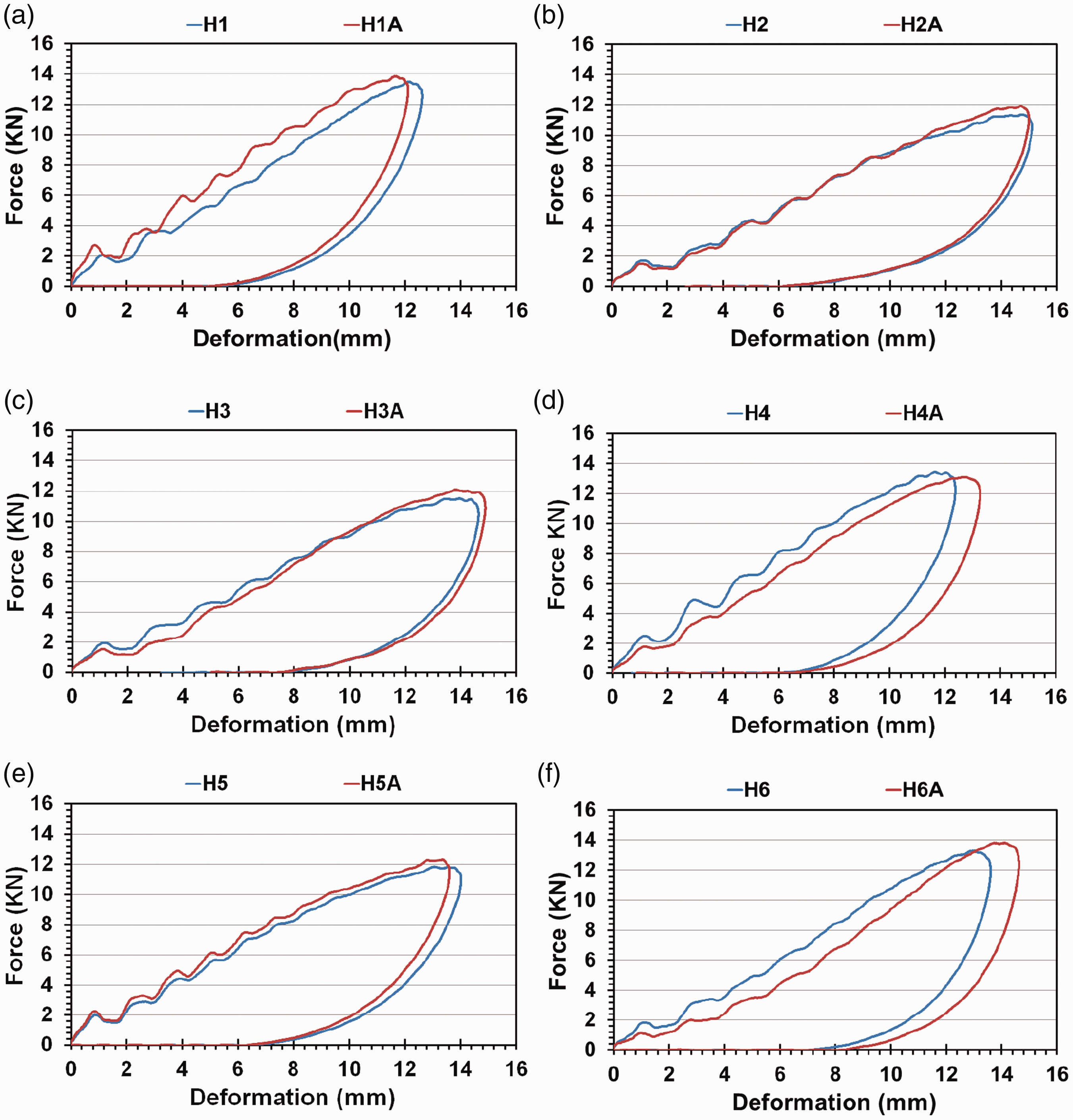
Hysteresis cycles for drop weight impact force-displacement curves of each hybrid and its alternative laminate at 100 J.
Generally, it can be seen that the peak force increases with the increase in the impact energy level, indicating the greater load bearing ability of the laminates at higher energy levels. Furthermore, the load–displacement curves illustrate that the displacement was increased with the increase in the impact energy levels, which was attributed to the impacted force of the impactor through the facing of the laminated layers.
Figure 16 shows the peak impact load with the impact energy for all laminated hybrid composites at 100 J. These results appear to indicate that the peak load vary much within all laminated composites. In terms of peak force, aramid composite performs better than kenaf composite at 100 J while hybrid laminates show an increased in peak force and absorbed energy compared to kenaf laminates. In addition, it shows that the kenaf composite has the lowest impact properties among other laminated hybrids. Hybrid H3A and H5A demonstrated close behaviour in terms of the final energy absorption, whose final energy absorption difference is 0.2 J and the difference in peak impact load is 0.22 KN. Besides, Hybrid H4 and H6 are showing the same close behaviour, the difference of energy absorption is 0.25 J and the difference in peak impact load is 0.17KN. As clearly shown by experimental results, both the laminate configuration and thickness heavily affect the laminated impact resistance, more and more as the impact energy increased.

Drop weight impact parameters of all hybrid laminates, peak impact force and absorbed energy at 100 J.
Drop weight impact damage mechanisms
The impacted surfaces of the laminated composite were examined by optical photography, as shown in Figure 17. It was observed that the damage was limited just to the impacted face without further propagation to the back face and back surface splitting. It was found that many different factors tend to affect the drop weight impact damage mechanisms in laminated composites, such as thickness, constituent properties, impactor size and shape, impact -velocity and energy [33]. According to these results, kenaf composites possess additional damage mechanisms than the aramid composites resulted in a high damage development in comparison with aramid composites such as debonding and fibrillation phenomena. However, it is worth noting that the damaged area for all laminated hybrids presents quite similar damage pattern as aramid composite because the outer layers at the impacted surfaces being made of aramid layers, which provide enhanced compliance. Conversely, the impacted H6A laminates exhibit surface damages approaching the pattern of and Kf laminates due to the presence of alternating kenaf layers [34].
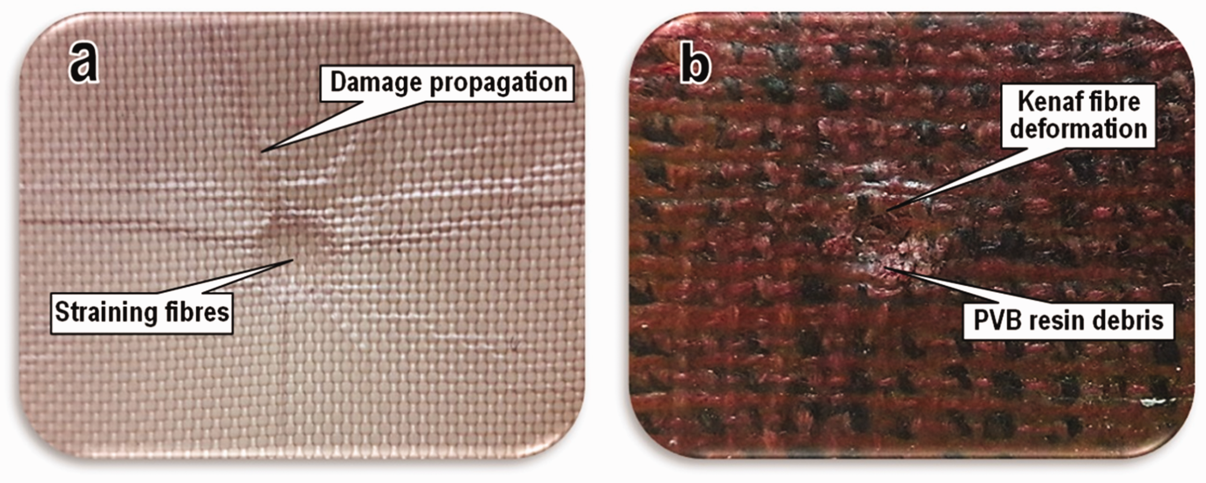
Optical pictures of damaged surface of hybrid composite laminates after drop-weight impact test at 100 J (a) aramid composite Ar and (b) kenaf composite Kf.
Conclusions
The effects of hybridization and stacking sequence of hybrid composite materials on the energy absorption under drop weight impact tests were investigated. Based on the results, the following specific conclusions were drawn: The experimental results demonstrated that the overall properties of the kenaf/aramid hybrid are dependent on the kenaf fibre content and stacking sequence layering. Compared to the pure kenaf composite, the hybrid composites absorb more impact energy and appear to have lower impact damage at the same impact energy level. The H1 (17aramid/2kenaf layers) Alt. exhibited the best impact properties compared to other hybrid composites, at 100J, the absorbed energy is 72.99J, and impact force is 13.95 kN. For all hybrids, placing woven kenaf layers alternate with aramid fabric layers provides higher impact loads than placing woven kenaf layers together and aramid layers separately for the same hybrid volume and thickness. Compared to kenaf composites, the hybridisation of Kenaf/aramid affects positively the energy absorption changes. The absorbed energy was significantly affected by the impact velocity. The difference in energy absorbed for the same hybrid content with different configurations increased at high impact energy levels 100 J. The impacted surfaces of the laminated composite were examined by optical photography; the damage was limited just to the impacted face without further propagation to the back face and back surface splitting. It is concluded that the damaged area for all laminated hybrids presents quite similar damage pattern as a conical shape and ductile failure.
This approach of producing hybrid composite materials is expected to develop new composite structures that are less costly and more readily available compared to the conventional helmet shell including the reduction in the use and content of the synthetic fibers. This research will open a new and more environmentally friendly alternative in military equipment, aerospace, marine, and civilian structures, which will reduce the use of aramid fabric in laminated composites, and meets the required baseline performance specifications.
Footnotes
Acknowledgements
The author would like to thank the Ministry of Higher Education & Scientific Research of Iraq and Mustansiriyah University, College of Engineering, Mechanical Engineering Department, for their support for the work contained in this study. Gratitude also extend to all technicians working in the Laboratory of Aerospace Engineering Department, Universiti Putra Malaysia, UPM, for their scientific assistance.
Declaration of conflicting interests
The author(s) declared no potential conflicts of interest with respect to the research, authorship, and/or publication of this article.
Funding
The author(s) received no financial support for the research, authorship, and/or publication of this article.