
Abstract
The longitudinal tubular braid texture (maypole braid) is an important texture in industrial textiles with extensive applications for composites reinforcement as a continuous form in a continuous process. This texture has a high strength in the longitudinal direction, while it is weak in its circumferential direction. The present work is to introduce an innovative structure named transversal tubular braid texture, whose structure is formed by the combination of braid and Leno technique in order to eliminate the weakness of longitudinal tubular braid texture and subsequently resist to the internal compression in its composite. Considering the complex production process of the introduced texture, prior to design a machine for its production, the structures of longitudinal and transversal tubular braid texture samples were produced as longitudinal and transversal lattice tubular braid textures using a 3D printer with the fused deposition modeling method in order to analyze and compare their mechanical properties. The required textures were primarily simulated by Rhino Ceros software and their lattice model data were transferred to the 3D printer. The produced tubular lattice samples were assessed by the standard Split Disk Mechanical Test for obtaining their hoop stresses. The hoop modulus of elasticity in transversal lattice tubular braid texture was approximately 120 times the longitudinal lattice tubular braid texture specimens. This suggests the proper design of this structure and resolves the weakness of longitudinal lattice tubular braid textures. The theoretical analysis of longitudinal and transversal lattice tubular braid textures was done by ANSYS software employing the data from the simulation software. The experimental results adequately correlated with the output results from the finite element analysis of the structures. This research work ensured that the mechanical strength of the introduced texture is desired to be produced continuously by a specially designed machine and used to reinforce tubular composites in an industrial continual process as the further work to be applied for high pressure fluids flows.
Keywords
Introduction
Braiding textures are produced in a variety of forms, such as 2D, 3D, and tubular. The properties of these textures are flexibility in production, energy absorption, and high tensile and torsional properties [1].
Longitudinal tubular braid texture (LTBT) is one of the most commonly used textures in the textile industry today, which has many applications with high mechanical capabilities, high production speed, lack of complexity of device, and low production price. This texture, while having high strength in its longitudinal direction, is faced with lack of dimensional instability in its periphery. Since the use of this texture is very common as reinforcement in tubular composites, the weakness of the texture is transferred to composite structure reinforced by it. Another advantage of tubular braid reinforced composites is their delamination resistant, since the entanglement of their reinforcing strands can act as a resisting agent for the separation of layers [2].
Many research activities have been carried out in relation to the production of tubular braid texture, such as texture angle variation and finding the optimum angle of texture and the production of composite samples [3]. Tubular composites prepared from tubular texture are one of the most important technologies developed in previous decades and the importance uses of this structure are increasing. Most of the tubular braid textures have been manufactured in single-layer form. Considering the fact that the single-layer does not meet all the necessary mechanical requirements, the multi-layer systems have been used [2,4,5]. By laminating and choosing the appropriate orientation of yarns in different directions, a wide range of mechanical properties can be improved and achieved [6].
The research history shows that most studies have been performed along the circumferential axis of LTBTs [2,3,4,7]. LTBTs are very weak in terms of axial compressive strength. Considering the production process of the longitudinal tubes, another set of yarns cannot be entangled in a peripheral (outer) direction with longitudinal yarns in the texture and they are circularly arranged in the wall of the tube. This has caused the structure not to have dimensional stability and also to be weak in radial direction [8].
Another disadvantage in the tubular braid structure is the opening of the texture (unraveling defect) at the end of the texture or during rupture. In order to improve the resistance in the circumferential direction (no transversal deformation), as well as to resolve other weaknesses in the tubular braid texture, many studies have been done on the optimization of the longitudinal braid peripheral structure by researchers. Various methods such as the angle variation of LTBT, LTBT shear layers, multilayer LTBT production system, LTBT’s with yarn in other directions are used to create dimensional stability along the circumferential direction of LTBT. All of the methods have presented in different methods. In fact, the structural geometry has the greatest impact force; the activities performed have been investigated according to the geometry of the structure. Zhou et al. have analyzed the pressure transfer reaction in a composite tube with a 3D longitudinal braid texture using the finite element method [4]. Guyader et al. [3] have simulated the relationship between production factors and the LTBT. The texture angle has been investigated by analyzing the single-axial tensile test in Goyal’s research and a model has been designed and presented for the LTBT reinforced composite [9]. Gautam et al. [10] have investigated the composite tubular braid model with variable braid texture angles on the parallel fibers.
Several studies have been done on the number of layers, their arrangements, and yarn types change in layers. Tadiboni et al. [2] have carried out a study on the compressive strength of LTBT composites with different numbers of layers. Hufenbach et al., in first, covered the cylindrical mold with a tubular braid texture, and then covered it with glass roving and repeated the previous steps three times for designing a layered tubular sample. The results of compression, torsional, flexural, and tensile tests performed in the longitudinal direction of the tube on the specimens have provided a model by finite element in the ANSYS software [11,12]. Pavlopoulou et al. [13] have performed hydrostatic compression tests on tubular textures with filament winding and LTBTs.
Wu et al. [14] have done research on the multilayer tubular braid production system for tubular braid connections. Zhou et al. [5] have analyzed the structure of the multi-layer longitudinal tubular braid structure with different numbers of layers. Bigaud et al. have also produced multi-layer longitudinal tubular braid samples of different angles, which are subject to geometric analysis and stress–strain analysis [15]. Lee et al. [16] have investigated the multi-layer longitudinal tubular braid subjected to torsional loading using a geometric model.
Lomov et al. [17] referred to modeling, meso-scale analysis on the LTBT with longitudinal yarn. Bilisik et al. [18] reported producing another structure that has been named the 3D woven tubular structure. Gurley et al. [19] have been working on the design of a modified lattice structure in tubular braid texture.
Davis reached an important point about the geometry of textile structures and similar printed structures. He was stated that there is a relationship between the behavior of the geometry (performance) of samples of textile structures and printed structures as same functionalized, which can help design and better construct and effective structures [20]. Wei Zhang et al. [21] have investigated the recovering force of shape memory of the longitudinal tubular braid. Shuting Liu et al. have worked on lattice structures reinforced with continuous carbon fiber with a new method. This method has used a modified 3D printer machine to produce continuous and uniform samples [22]. Gowthaman et al. [23] have printed and investigated textile textures under different raw materials and devices, and reported the results with properties such as softness, pendants, and the modulus of elasticity.
According to studies on various structural geometries, it can be concluded that a high-module texture can be achieved by creating proper entanglements among yarns. According to this result, it is anticipated that a proper structure named transversal tubular braid texture (TTBT) can be obtained by using Leno technique almost perpendicular to the braid axial, so that the axial and hoop stresses created by an internal compression (hydrostatic compression) can be properly tolerated.
In this research, the structure of LTBT (maypole) has been investigated. The applications of this texture have been pointed in the introduction as highlighted in the text. The comparison between LTBT and TTBT can be summarized as follows:
Disadvantages of LTBT: Dimensional instability in radial and circumferential direction Low compressive strength in the longitudinal direction of tubular braid structure Unraveling defect (texture opening during cutting or finishing work)
Advantages of TTBT: Create dimensional stability in transverse direction Increasing radial and circumferential resistance Increase the compressive strength the longitudinal direction of the tubular structure Disappearance of unraveling defect (texture opening during cutting or finishing work) High tensile strength along the tubular longitudinal structure High torsional strength of structure Sample production with different cross sections
Experimental work
The production of the TTBT has been technically proved by a specially designed machine. Prior to this, it was decided to simulate the proposed structure and produce its lattice sample accordingly using 3D printing method to ensure its reliability by assessing its properties comparatively.
Definition of structures
In order to define the apparent of required structures, the proper relationship among strands, and the interconnection surface area between strands and to ensure the uniformity of structures, one single strand with elliptical cross-section and waved path was depicted based on previous work [25] as shown in Figure 1. The specifications of the strand was then used to determine the cross-sectional dimensions, the texture arrangement, and the positioning angle in the model of lattice tubular braid structures and to analyze the models by finite element method at a real scale [13].

View of cross section and path of yarns (a), depicted cross section (b), and 3D display of strand (c) [25].
Design of structures
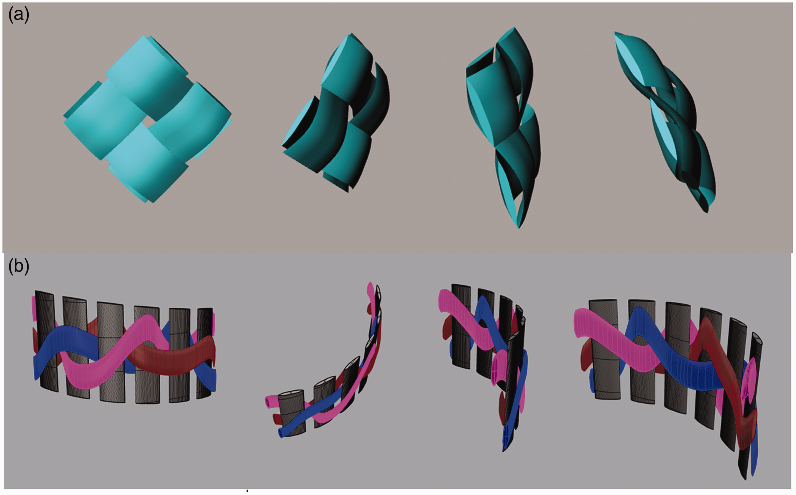
In order to empirically and theoretically analyze the TTBT compared to control texture (LTBT), the required structures were first designed by a Rhino Ceros design software employing the specifications of the defined strand. The view of longitudinal and transversal lattice tubular braid textures (LLTBT and TLTBT) designed in Rhino software has been shown in Figure 2.

View of longitudinal (a) and transversal (b) lattice tubular braid textures designed in Rhino software.
3D printing of structures
The textures were initially modeled at actual sizes taken from the defined cross-section and the designed models were then magnified two, three, and four times, so that they could be made by the 3D printer. The model at four-times of the actual size was found appropriate.
The G codes of the proper designed lattice structures were transferred to a fused deposition modeling (FDM) 3D printer. The 3D printer (Hermes X1 model) and samples of printed lattice braid textures have been shown in Figure 3.

View of 3D printed longitudinal (a) and transversal (b) lattice tubular braid textures, and 3D printer (c).
The material used in this study was the Chinese poly lactic acid (PLA) filament. The specification of the PLA filament is shown in Table 1.
Specification of PLA material used in the research.

PLA: poly lactic acid
The printer settings were kept constant for all specimens as they are in Table 2.
Printer settings for 3D printed samples.

One of the influential factors in printing is the weight of the samples. The amount of used polymer in each sample was calculated according to its geometry and considered in its design, so that all samples were almost similar in weight after their production (Table 3), while their geometrical specifications were the same (Table 4).
Weigh of printed samples.

LLTBT: longitudinal lattice tubular braid texture; TLTBT: transversal lattice tubular braid texture.
Geometrical specifications of printed samples.

LLTBT: longitudinal lattice tubular braid texture; TLTBT: transversal lattice tubular braid texture.
Mechanical test of structures
In order to evaluate the mechanical properties of printed samples, the tests were carried out according to the standard method Split Disk Mechanical Test (ASTM-D2290). A schematic representation of the jaws and sample dimensions used in the standard is shown in Figure 4 [26]. In this method, the speed of the cross head (tensile rate) can be selected between 2.5 and 12.5 mm/min. Here, the 2.5 mm/min is selected. The mechanical properties of structures such as the maximum internal load resistance, the length variation at the tear point, and the elasticity coefficient were measured. Regarding the results of the experiment, it was possible to examine and model the performance of the samples under loading conditions.
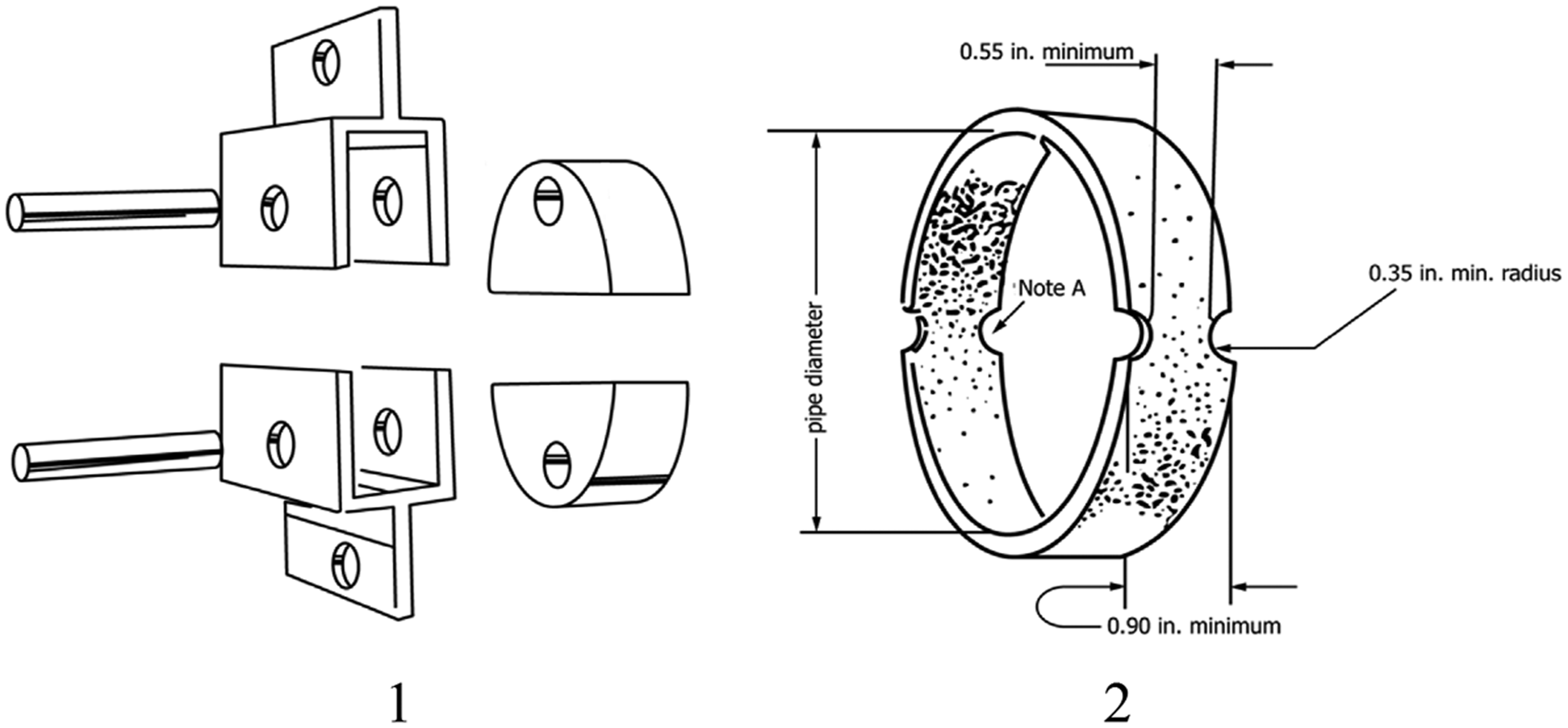
Schematic representation of jaws (1) and sample dimensions (2) used in the standard ASTM-D2290 [26].
A precise calculation was made to establish the relationship between printed samples and standard sizes. There was a correct consistency when the standard sizes were doubled and the sizes of the printed samples were four times the actual design. Considering the low strength of the specimens against the force applied to their structures, as well as not eliminating the entire structures due to the creation of a notch in the samples, no notches were applied to the printed textures for Split Disk Mechanical Test. The internal diameter of the structures was considered as the distance between the jaws of the device. The view of the measurement device for mechanical properties and the Split Disk Mechanical Test device are shown in Figure 5. Data of textures hoop modulus experimental are shown in Table 5.

Measurement device for mechanical properties (a) and Split Disk Mechanical Test device (b).
Textures hoop modulus experimental data.
LLTBT: longitudinal lattice tubular braid texture; TLTBT: transversal lattice tubular braid texture.
The stress in samples was calculated using equation (1). The problem solving was performed based on plate stress method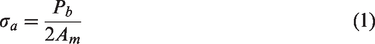

According to the strength theory of materials in thin-walled cylinders, the hoop stress will be twice the axial stress [19]. In the theory of thin-walled walls, when wall thickness to sample diameter is one-twentieth (0.05), equation (3) can be used to obtain hoop and axial stresses (Figure 6). To obtain the general solution in polar coordinates using a general Michelle solution in the theory of elasticity, an erratic stress function was used. Subsequently, with axial symmetric response and plane strain solution, it was possible to solve the cylindrical problem of a solid wall subjected to uniform boundary pressure. Ultimately, after solving this problem, it was possible to obtain tensile and circumferential (hoop) stresses, assuming that the radial stress was considered to be zero with respect to its very low level. According to the results obtained from the theory of elasticity for thin-walled cylinders, the circumferential and axial stresses were obtained. It can be concluded that the circumferential stresses were twice the axial stresses. The problem was solved by the plane strain method [27].

Thin-wall cylinder subjected to internal compression (a) and a cut of a cylindrical section (b) [27].
Simulation of structures
To analyze the structures numerically by finite elements method, the cell selected in each texture was identified by Rhino software and transferred to ANSYS software to be analyzed by creating boundary conditions and the loading method. The simulated repeat cells of LLTBT and TLTBT are shown in Figure 7.

View of simulated repeat cells of longitudinal (a) and transversal (b) lattice tubular braid textures.
The contact surface between two crossed yarns in the simulated models was set to the minimum of 0.001 mm to increase the accuracy of the simulation as well as having a faultless printing performance [25]. Thus, the crossed yarns surfaces (Figure 8) were not clamped together while they were close to each other as much as possible to be produced by 3D printing. This was also considered and applied in the analysis of the models.
View of yarns in simulated longitudinal (a) and transversal (b) lattice tubular braid textures repeat cells.
Theoretical analysis of structures
One single waved strand was primarily printed as the base structure of tubular textures. Its data, obtained from a simple tensile test, was used for finding the stress–strain diagrams in the single cell of each simulated texture. The stress–strain curve and Young’s modulus were obtained and the Poisson ratio was calculated by the image processing method [28]. A printed wavy strand is shown in Figure 9.

View of printed wavy tape.
The strand information was entered into ANSYS software. After selecting the correct geometry and appropriate triangular meshing on all surfaces, the compression loading was selected as a vector on the inner surface of the cells. In order to analyze the textures, their structures were considered as isotropic material. To perform high-precision calculations, the level of contact between surfaces in ANSYS software was defined hard and slippery which led to getting precise results from the repeating cell of each tubular texture. The graphs obtained from the experimental results and the data of the finite element modeling are shown in Figure 10.
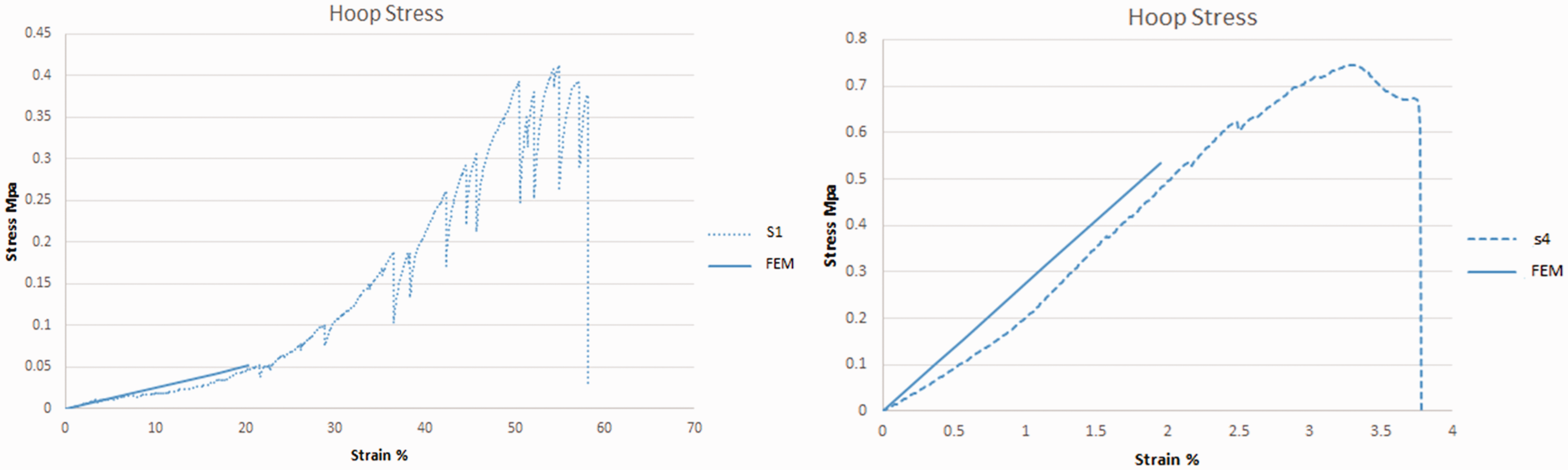
Experimental results and outcome of finite elements analysis graphs of longitudinal (S1, FEM) and transversal (S4, FEM) lattice tubular braid textures.
The outputs of ANSYS software including general deformation, elastic strain, stress, and strain energy for the repeating cell of LLTBT and TLTBT can be observed in Figures 11 and 12. Their obtained experimental and analytical elastic constants are presented in Table 6.

General deformation, elastic strain, stress and strain energy for the repeating cell of longitudinal lattice tubular braid texture from above to the bottom.

General deformation, elastic strain, stress, and strain energy for repeating cell of longitudinal lattice tubular braid texture from above to the bottom.
Elastic constants of LLTBT and TLTBT.

LLTBT: longitudinal lattice tubular braid texture; TLTBT: transversal lattice tubular braid texture.
Results and discussion
ANSYS software was used to analyze the compression behavior of these structures. Graphical output by displacement theory (strain) shows structural analysis. In this case, it shows the stress concentration points in the structure and the (maximum and minimum) force applied to the structure. In this research, the solution is solved by finite element theory. The predicted output is accurate with respect to the structural parameters in most structures.
There are two ways to analyze structures with this software. In the first method, the entire structure is given to ANSYS after design by a design software. After meshing the structure and defining boundary conditions, it solves the problem. This method is mostly used for asymmetric and heterogeneous structures. The second method is mostly used for symmetric structures and structures with repeating units. In this method, the representative volume element (duplicate cell) is given to ANSYS after design by a design software. After meshing the structure and defining boundary conditions, it solves the problem. The amount of calculations in this method is lower and the prediction accuracy is increased. In this study, the second method was used. In the revised manuscript, the graphical output is shown in Figures 11 and 12 and the numerical calculation output is shown in Table 6.
All factors influencing the printing of samples were considered constant to simulate and compare the effects of lattice structures during loading. All specimens were produced at the temperature of 25–27°C and the standard ambient humidity, while items like nonuniformity of the consumable filament (e.g., impurities), the setting of a printing machine, or inappropriate environmental conditions cause the printing of all samples with high error (Figure 13, for instance). But these variations have the same effect on both samples. Therefore, we assumed that these will not make a difference between two samples.

View of healthy print sample (a), incomplete sample printing, low filament injection state (b), and incomplete sample printing of high filament injection state (c).
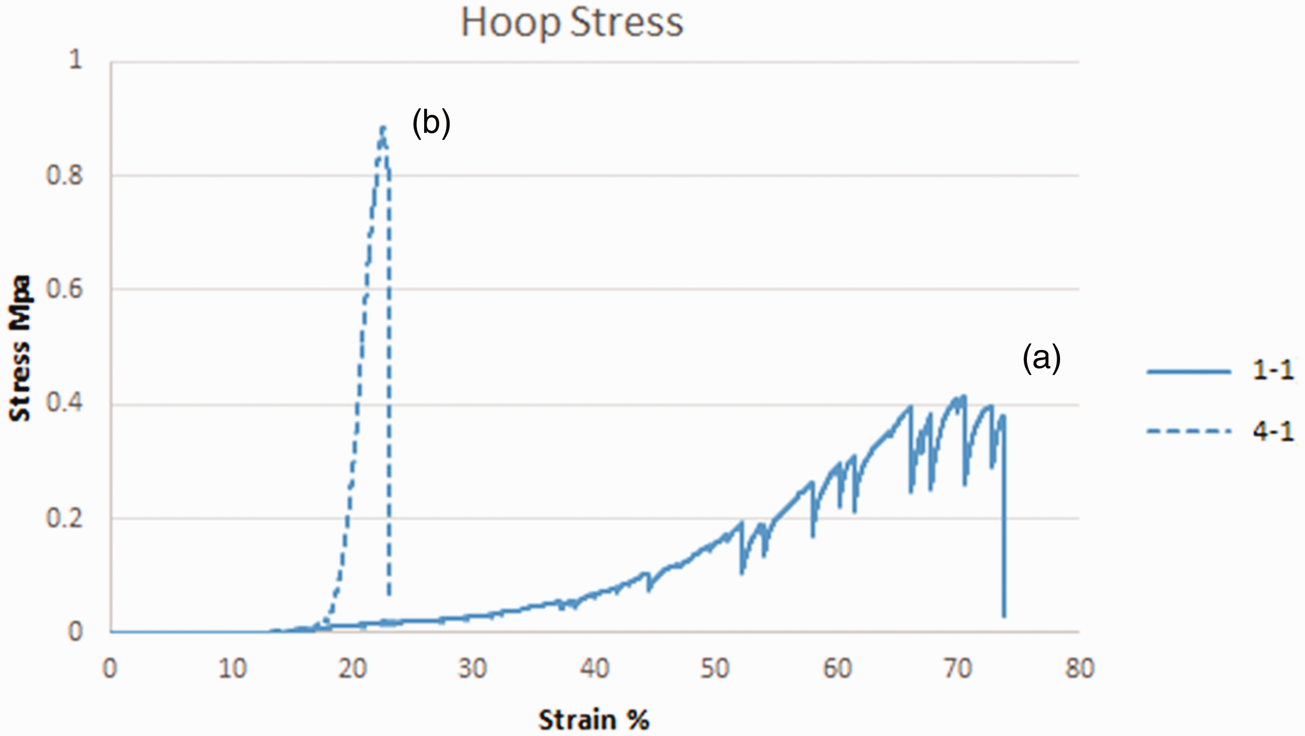
By reducing the print speed of the sample to 40 mm/s and raising the temperature to 215°C, the cavities or errors in the samples were reduced to almost zero. There is no bond between the yarns in the designed textures (Figure 8). A set of hoop stress–strain diagrams of LLTBT and TLTBT samples subjected to mechanical tests is shown in Figure 14. In these graphs, no changes in strain are observed from 0% to 15%, because the jaws were set on the machine in such a way that, after each test, they returned to their predefined positions, so that the distance between the two jaws was constant. Consequently, at this strain range, the jaws were connected to the walls of the tubular structures, and thus, the starting point of the graphs is at 15% strain.

Hoop stress–strain diagrams of longitudinal (a) and transversal (b) lattice tubular braid textures.
There are fluctuation peaks in the diagram associated with the LLTBTs which were due to the displacement of strands toward each others. As a result of this event, the LLTBTs were opened with a slight resistance, so that many ascending and descending peaks can be observed in the graphs instead of sudden failure. This is while the TLTBTs resisted opening at the same loading until their sudden failures occurred. This causes the average hoop elastic modulus of the samples in graph B to be approximately 120 times the sample in graph A (Table 7). This is the case that occurred in single-layer specimens while it is expected that the modulus in multi-layer mode will multiply several times with textile materials such as yarns. The hoop stress–strain diagrams of the LLTBT and TLTBT are shown in Figure 15 to be compared.
Elastic modulus LLTBT and TLTBT.

LLTBT: longitudinal lattice tubular braid texture; TLTBT: transversal lattice tubular braid texture.
Hoop stress–strain diagram of longitudinal (a) and transversal (b) lattice tubular braid texture.
The experimental strain energy and the analytical are calculated in the Table 8. The strain energy is calculated in the red area are shown in Figure 16. The specimens after the Split Disk Mechanical Test and their failure regions are shown in Figure 17.
Textures strain energy data.

LLTBT: longitudinal lattice tubular braid texture; TLTBT: transversal lattice tubular braid texture.

The Strain energy is calculated in the red area.

Samples of longitudinal (a) and transversal (b) lattice tubular braid texture after Split Disk Mechanical Test and their failure regions.
Conclusion
This research investigated the reliability of the TTBT combined of braid and Leno techniques as composite reinforcement under internal compression by eliminating the weakness of maypole braids (LTBT). The 3D printed samples (LLTBT and TLTBT) similar to LTBT and TTBT were produced with the FDM method and subjected to the Split Disk Mechanical Test. The printed structures behaved such as those produced by textile materials. This behavior was observed in the LLTBTs, which acted like textile tubular braid textures, and their textures were opened in a short time without any tear. While in the innovated TLTBTs, this led to tears in their textures after a longer time. This caused the structure of the TLTBT could tolerate the highest hoop stress. The increase in the hoop modulus of elasticity in TLTBT specimens was approximately 120 times that of the LLTBT ones. These results were also confirmed by the finite element analysis of each LLTBT and TLTBT models.
The empirical and theoretical results considerably ensure that the introduce texture has a proper potential to be employed as textile reinforcement for the production of high-performance tubular composites in an industrial continual process.
Footnotes
Declaration of conflicting interests
The author(s) declared no potential conflicts of interest with respect to the research, authorship, and/or publication of this article.
Funding
The author(s) received no financial support for the research, authorship, and/or publication of this article.